EP4425052A1 - Gargerät mit einer kamera zur überwachung des garraums - Google Patents
Gargerät mit einer kamera zur überwachung des garraums Download PDFInfo
- Publication number
- EP4425052A1 EP4425052A1 EP24150653.4A EP24150653A EP4425052A1 EP 4425052 A1 EP4425052 A1 EP 4425052A1 EP 24150653 A EP24150653 A EP 24150653A EP 4425052 A1 EP4425052 A1 EP 4425052A1
- Authority
- EP
- European Patent Office
- Prior art keywords
- cooking chamber
- camera
- cooking
- niche
- ceiling
- Prior art date
- Legal status (The legal status is an assumption and is not a legal conclusion. Google has not performed a legal analysis and makes no representation as to the accuracy of the status listed.)
- Pending
Links
- 238000010411 cooking Methods 0.000 title claims abstract description 184
- 238000012544 monitoring process Methods 0.000 title claims abstract description 7
- 238000010438 heat treatment Methods 0.000 claims abstract description 12
- 238000009413 insulation Methods 0.000 description 17
- 235000013305 food Nutrition 0.000 description 10
- 238000000034 method Methods 0.000 description 4
- TZCXTZWJZNENPQ-UHFFFAOYSA-L barium sulfate Chemical compound [Ba+2].[O-]S([O-])(=O)=O TZCXTZWJZNENPQ-UHFFFAOYSA-L 0.000 description 1
- 238000011109 contamination Methods 0.000 description 1
- 230000001419 dependent effect Effects 0.000 description 1
- 238000005192 partition Methods 0.000 description 1
- 238000001454 recorded image Methods 0.000 description 1
Images
Classifications
-
- F—MECHANICAL ENGINEERING; LIGHTING; HEATING; WEAPONS; BLASTING
- F24—HEATING; RANGES; VENTILATING
- F24C—DOMESTIC STOVES OR RANGES ; DETAILS OF DOMESTIC STOVES OR RANGES, OF GENERAL APPLICATION
- F24C7/00—Stoves or ranges heated by electric energy
- F24C7/08—Arrangement or mounting of control or safety devices
- F24C7/082—Arrangement or mounting of control or safety devices on ranges, e.g. control panels, illumination
- F24C7/085—Arrangement or mounting of control or safety devices on ranges, e.g. control panels, illumination on baking ovens
-
- F—MECHANICAL ENGINEERING; LIGHTING; HEATING; WEAPONS; BLASTING
- F24—HEATING; RANGES; VENTILATING
- F24C—DOMESTIC STOVES OR RANGES ; DETAILS OF DOMESTIC STOVES OR RANGES, OF GENERAL APPLICATION
- F24C7/00—Stoves or ranges heated by electric energy
- F24C7/02—Stoves or ranges heated by electric energy using microwaves
Definitions
- the invention relates to a cooking appliance, in particular a household oven, comprising a cooking chamber with an inner cooking chamber wall, a heating device and a camera for monitoring the cooking chamber.
- the inner cooking chamber wall comprises a cooking chamber floor, a cooking chamber ceiling, a cooking chamber rear wall and cooking chamber side walls.
- Cooking appliances in private households, especially ovens or steam cookers, with cameras for monitoring the cooking chamber are well known.
- the recorded images can be transmitted to a mobile phone via a radio connection, for example, and the user can follow the cooking process in the cooking chamber via the mobile phone.
- the user can, for example, follow how the browning of the food in the cooking chamber develops without having to be near the cooking appliance.
- Other cooking devices not only transmit an image from the cooking chamber, but also use the image information to control the cooking process.
- a change in the color of the food being cooked can, for example, be interpreted as browning, so that the cooking process is automatically stopped once a certain browning level is reached.
- the task is to provide a cooking appliance which has a camera and the camera is arranged in the cooking appliance in a way which saves as much space as possible.
- the camera is arranged at least partially above the cooking chamber ceiling.
- the cooking chamber ceiling is the inner cooking chamber wall arranged on the top of the cooking chamber.
- the cooking chamber ceiling is a flat, horizontally aligned cooking chamber wall.
- the camera is at least partially positioned above the cooking chamber ceiling, this means that the camera is at least partially positioned outside the cooking chamber. This means that the camera is better protected from heat than if it were positioned completely inside the cooking chamber. In addition, the entire cooking chamber can be monitored from this position.
- the camera is arranged partially below the cooking chamber ceiling, i.e. inside the cooking chamber. This means that the camera is arranged both partially above and partially below the cooking chamber ceiling. This reduces the space taken up by the camera outside the cooking chamber or above the cooking chamber ceiling. There is more space available outside the cooking chamber for the arrangement of other components, such as the control electronics.
- the cooking chamber ceiling advantageously includes an opening.
- a camera niche in which the camera is partially arranged.
- the part of the camera which is arranged inside the cooking chamber and below the cooking chamber ceiling is not located inside but outside the camera niche. If, as in this case, the camera is arranged partly inside the camera niche and partly inside the cooking chamber, this means that the camera is arranged as close to the cooking chamber as possible and therefore the opening in the cooking chamber ceiling can be made relatively small. The thermal insulation of the cooking chamber is thereby improved.
- the camera niche separates the camera from other components, in particular from the adjacent insulation, and ensures that the camera has a clear view into the cooking chamber.
- the opening has a circular, oval or rectangular shape and/or the camera niche has the shape of an oblique, blunt circular cone.
- the shape of the oblique circular cone enables the camera to look into the cooking chamber at an angle to the vertical.
- the camera niche is openly connected to the cooking chamber.
- the interior of the camera niche is therefore not isolated from the cooking chamber, ie not by a partition or another separating element from the cooking chamber. Vapors that arise in the cooking chamber can, for example, flow into the camera niche and along the camera.
- an insulation layer is provided above the cooking chamber ceiling and immediately adjacent to the cooking chamber ceiling.
- the camera niche is arranged within the insulation layer and does not protrude above the insulation layer. This means that the camera niche is embedded in the insulation layer at the height of the insulation layer. If the camera niche does not protrude above the insulation layer, the camera niche does not take up unnecessary space outside the insulation layer.
- the camera advantageously has a front screen and the front screen is arranged partly below the cooking chamber ceiling and partly above the cooking chamber ceiling.
- the front screen is the part of the camera through which light rays enter the camera from outside. This means that the front screen forms an outer boundary of the camera, in this case directed downwards towards the cooking chamber.
- the camera's line of sight is directed at an angle to the vertical.
- the camera's line of sight is directed at an angle to the horizontal. If the line of sight is directed at an angle and not parallel to the vertical or horizontal, the camera can Capture both lateral image information and image information from above of the food items arranged in the cooking chamber. This allows particularly advantageous monitoring of the food items.
- the camera is spaced from the center of the cooking chamber ceiling, in particular at least 5 cm, in particular at least 10 cm, from the center of the cooking chamber ceiling. This allows a partial view of the food being cooked from the side, which improves the assessment of the food being cooked.
- the camera it is advantageous for the camera to extend vertically into the cooking chamber by a maximum of 3 cm, and in particular by a maximum of 2 cm, below the cooking chamber ceiling. If it penetrates too far into the cooking chamber, the camera would be exposed to too high a risk of contamination and would also restrict the movement of food and, for example, baking trays within the cooking chamber too much.
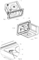
- the Fig. 1, 2 and 2a show the essential components of a cooking appliance.
- the cooking appliance shown is a so-called combi-steamer. This combines steam functions and hot air, and this combination leads to a very good cooking result.
- the hot air provides good heat, while the steam generates a suitable climate.
- the food does not dry out and gets a golden brown surface.
- the cooking appliance comprises a cooking chamber housing 1 (also called a muffle), which was manufactured using a deep-drawing process.
- the cooking chamber housing 1 forms the cooking chamber 2 and a cooking chamber inner wall 3, which delimits the cooking chamber 2 from the outside.
- the cooking chamber inner wall 3 comprises a cooking chamber floor 31, a cooking chamber ceiling 32, a cooking chamber rear wall 33 (see Fig.4 ) and cooking chamber side walls 34.
- the cooking appliance also includes various heating devices 4.
- a bottom heat heating device 41 is located on the underside of the cooking chamber housing.
- a circulating air heating device 42 is located on the back of the cooking appliance (see Fig.4 ) with a heater and a fan.
- a heating device for generating the steam is not shown.
- FIG. 3 to 5 Reference is made to the invention.
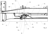
- a camera 7 is arranged partly above the cooking chamber ceiling 32 within the camera niche 6 and partly below the cooking chamber ceiling 32 in the cooking chamber 2. This is shown by the Fig.5 well illustrated.
- the camera 7 comprises an image sensor 71, a lens 72 with lenses, a front screen 73 and an air space 74 between the lens 72 and the front screen 73 (see Fig. 4a ).
- the front panel 73 and the air space 74 insulate the lens 72 and the image sensor 71 from heat and dirt from the cooking chamber 2.
- the opening 5 on the cooking chamber ceiling 32 has an oval shape (see Fig. 2b) and does not close the connection between the camera niche 6 and the cooking chamber 2. This means that vapors that arise in the cooking chamber 2 can penetrate unhindered through the opening 5 into the camera niche 6.
- Fig.5 visible that the camera niche 6 has the shape of a truncated, oblique cone.
- the walls of the camera niche 6, which form the shape of the truncated, oblique cone, are marked with the reference number 61.
- the viewing direction 75 of the camera 7 is oblique to the vertical 8 with an angle 9 of 25°.
- the camera 7 is therefore positioned towards the center 9 of the cooking chamber ceiling 32 (see Fig.3 ) spaced apart.
- the distance 10 (dashed line in Fig.3 ) between the center 9 of the cooking chamber ceiling 32 and the camera 7 is approximately 22 cm. Due to the oblique viewing direction 75, which is based on a lateral arrangement of the camera 7, the items being cooked arranged in the cooking chamber 2 can be observed particularly well. At this viewing angle 9, the items being cooked are visible both partially from above and partially from the side.
- a lower part 76 of the camera 7 is arranged inside the cooking chamber 2 and below the cooking chamber ceiling 32.
- An upper part 77 of the camera 7 is arranged inside the camera niche 6 and thus arranged above the cooking chamber ceiling 32.
- the upper part 77 of the camera 7 is not arranged in the cooking chamber 2, but in the camera niche 6.
- the upper part 77 is significantly larger in relation to the entire camera 7, as is the lower part 77.
- the camera projects approximately 1.5 cm into the cooking chamber 2. This vertical distance of approximately 1.5 cm is marked by the reference number 78. It extends from the cooking chamber ceiling 32 to the lower end of the camera 7.
- the front window 73 is arranged partly below the cooking chamber ceiling 32 and partly above the cooking chamber ceiling 32.
- An insulation layer 11 is arranged at the height of the camera niche 7 and thus surrounds the camera niche 7, as well as above the cooking chamber ceiling 32 and directly adjacent to the cooking chamber ceiling 32. This insulates the cooking chamber 2 from the outside so that the heat generated in the cooking chamber 2 remains as much as possible within the cooking chamber 2 and does not penetrate to the outside.
- the camera niche 6 and the camera 7 do not protrude above the insulation layer 11, i.e. the camera niche 6 and the camera 7 are arranged exclusively below the upper boundary 12 of the insulation layer 11.
- the upper boundary 12 lies between the insulation layer 11 and an electronics compartment 13 arranged above the insulation layer 12.
- the control of the cooking appliance and other electronic components are arranged in the electronics compartment 13. Neither the camera niche 6 nor the camera 7 protrude into the electronics compartment 13.
Landscapes
- Engineering & Computer Science (AREA)
- Chemical & Material Sciences (AREA)
- Combustion & Propulsion (AREA)
- Mechanical Engineering (AREA)
- General Engineering & Computer Science (AREA)
- Electric Stoves And Ranges (AREA)
Abstract
Die Erfindung betrifft ein Gargerät, insbesondere einen Haushaltsbackofen, umfassend einen Garraum (2) mit einer Garrauminnenwand. Die Garrauminnenwand umfasst einen Garraumboden, eine Garraumdecke (32), eine Garraumrückwand (33) und Garraumseitenwände. Zudem umfasst das Gargerät eine Heizvorrichtung und eine Kamera (7) zur Überwachung des Garraums (2). Die Kamera (7) ist zumindest teilweise oberhalb der Garraumdecke (32) angeordnet.
Description
- Die Erfindung betrifft ein Gargerät, insbesondere einen Haushaltsbackofen, umfassend einen Garraum mit einer Garrauminnenwand, eine Heizvorrichtung und eine Kamera zur Überwachung des Garraums. Die Garrauminnenwand umfasst einen Garraumboden, eine Garraumdecke, eine Garraumrückwand und Garraumseitenwände.
- Gargeräte in Privathaushalten, insbesondere Backöfen oder Dampfgargeräte, mit Kameras zur Überwachung des Garraums sind bekannt. Die aufgenommenen Bilder können beispielsweise über eine Funkverbindung auf ein Mobiltelefon übertragen werden und der Benutzer kann den Garprozess im Garraum über das Mobiltelefon verfolgen. Der Benutzer kann beispielsweise verfolgen, wie sich die Bräunung der Gargüter im Garraum entwickelt, ohne dass er sich in der Nähe des Gargerätes aufhalten müsste.
- Andere Gargeräte übertragen nicht nur ein Bild aus dem Garraum, sondern nutzen die Bildinformationen, um den Garprozess zu steuern. Eine Farbänderung der Gargüter kann beispielsweise als Bräunung interpretiert werden, sodass der Garprozess ab einem bestimmten Bräunungslevel automatisch beendet wird.
- Es stellt sich die Aufgabe, ein Gargerät bereitzustellen, welches eine Kamera aufweist und die Kamera im Gargerät möglichst platzsparend angeordnet ist.
- Diese Aufgabe wird vom Gargerät gemäss dem unabhängigen Anspruch gelöst. Ein solches Gargerät ist insbesondere ein Gargerät zur Verwendung in einem Privathaushalt, insbesondere ein Backofen, ein Dampfgargerät, ein Mikrowellengerät oder ein Gerät mit kombinierten Garfunktionen. Das Gargerät umfasst
- einen Garraum mit einer Garrauminnenwand, wobei die Garrauminnenwand einen Garraumboden, eine Garraumdecke, eine Garraumrückwand und Garraumseitenwände umfasst. Die Garrauminnenwand begrenzt das Volumen des Garraums. In den Garraum können Lebensmittel eingeschoben werden, welche mittels des Gargeräts gegart werden sollen. Diese Lebensmittel können auch als Gargüter bezeichnet werden.
- eine Heizvorrichtung. Die Gargüter werden mittels der Heizvorrichtung gegart. Eine Heizvorrichtung ist insbesondere eine Ober-/Unterhitze, eine Umluftheizfunktion, eine Grillfunktion, ein Mikrowellengenerator oder eine Heizvorrichtung zur Generierung von Dampf.
- eine Kamera zur Überwachung des Garraums. Die Kamera generiert insbesondere Bilder und Videos oder einen Live-Stream, wobei diese Bilddaten von einer Steuerung des Gargeräts verarbeitet werden und/oder an ein Bildausgabegerät übermittelt werden. Als Bildausgabegerät kommt beispielsweise ein Mobiltelefon infrage. Der Begriff "Kamera" umfasst insbesondere einen Bildsensor und ein Objektiv, insbesondere auch eine vor dem Objektiv angeordnete Frontscheibe zum Schutz des Objektivs.
- Die Kamera ist zumindest teilweise oberhalb der Garraumdecke angeordnet. Die Garraumdecke ist die an der Oberseite des Garraums angeordnete Garrauminnenwand. Insbesondere ist die Garraumdecke eine ebene, horizontal ausgerichtete Garraumwand.
- Ist die Kamera zumindest teilweise oberhalb der Garraumdecke angeordnet, bedeutet dies, dass die Kamera zumindest teilweise ausserhalb des Garraums angeordnet ist. Dadurch ist die Kamera vor Hitze besser geschützt, wie wenn sie vollständig im Garraum angeordnet wäre. Zudem kann aus dieser Position möglichst der gesamte Garraum überwacht werden.
- Mit Vorteil ist die Kamera teilweise unterhalb der Garraumdecke, d.h. innerhalb des Garraums, angeordnet. Dies bedeutet, dass die Kamera sowohl teilweise oberhalb als auch teilweise unterhalb der Garraumdecke angeordnet ist. Damit wird der von der Kamera ausserhalb des Garraums bzw. oberhalb der Garraumdecke beanspruchte Raum reduziert. Es steht ausserhalb des Garraums mehr Raum für die Anordnung weiterer Bauelemente zur Verfügung, wie z.B. die Steuerelektronik.
- Vorteilhaft umfasst die Garraumdecke eine Öffnung. Oberhalb der Garraumdecke und an die Öffnung angrenzend ist eine Kameranische vorhanden, in welcher die Kamera teilweise angeordnet ist. Derjenige Teil der Kamera, welcher innerhalb des Garraums und unterhalb der Garraumdecke angeordnet ist, befindet sich nicht innerhalb, sondern ausserhalb der Kameranische. Ist, wie vorliegend, die Kamera teilweise innerhalb der Kameranische und teilweise innerhalb des Garraums angeordnet, bedeutet dies, dass die Kamera möglichst nahe am Garraum angeordnet ist und deshalb die Öffnung in der Garraumdecke verhältnismässig klein ausgestaltet werden kann. Die thermische Isolation des Garraums wird dadurch verbessert.
- Die Kameranische trennt die Kamera von weiteren Bauteilen, insbesondere von der benachbarten Isolation, und stellt sicher, dass die Kamera freien Blick in den Garraum hat.
- Insbesondere weist die Öffnung eine Kreis-, eine Oval- oder eine Rechteckform auf und/oder die Kameranische weist die Form eines schiefen, stumpfen, Kreiskegels auf. Die Form des schiefen Kreiskegels ermöglicht, dass die Kamera mit einer zur Vertikalen schrägen Blickrichtung in den Garraum schauen kann.
- Insbesondere ist die Kameranische offen mit dem Garraum verbunden. Der Innenraum der Kameranische ist somit gegen den Garraum nicht isoliert, d.h. nicht durch eine Trennscheibe oder durch einen anderen Trennkörper vom Garraum getrennt. Im Garraum entstehende Dünste können beispielsweise in die Kameranische hinein und entlang der Kamera strömen.
- In einer besonderen Ausführungsform ist oberhalb der Garraumdecke und unmittelbar an die Garraumdecke angrenzend eine Isolationsschicht vorhanden. Die Kameranische ist innerhalb der Isolationsschicht angeordnet und sie überragt die Isolationsschicht nach oben nicht. D.h. die Kameranische ist auf der Höhe der Isolationsschicht in dieser eingebettet. Überragt die Kameranische die Isolationsschicht gegen oben nicht, nimmt die Kameranische ausserhalb der Isolationsschicht nicht unnötig Raum in Anspruch.
- Insbesondere ist oberhalb der Garraumdecke und unmittelbar an die Garraumdecke angrenzend eine Isolationsschicht vorhanden. Oberhalb der Isolationsschicht ist ein Elektronikraum mit Steuerelektronik angeordnet, wobei die Kameranische vollständig unterhalb des Elektronikraums innerhalb der Isolationsschicht angeordnet ist. Dies hat den Vorteil, dass die Kameranische keinen Raum innerhalb des Elektronikraums beansprucht und in diesem genügend Raum für weitere Bauteile verfügbar ist.
- Mit Vorteil weist die Kamera eine Frontscheibe auf und die Frontscheibe ist teilweise unterhalb der Garraumdecke und teilweise oberhalb der Garraumdecke angeordnet. Die Frontscheibe ist dasjenige Bauteil der Kamera, durch welche Lichtstrahlen in die Kamera von ausserhalb eintreten. D.h. die Frontscheibe bildet eine äussere Begrenzung der Kamera, im vorliegenden Fall gegen den Garraum nach unten gerichtet.
- Vorteilhaft ist die Blickrichtung der Kamera schräg zur Vertikalen gerichtet. Insbesondere ist die Blickrichtung der Kamera schräg zur Horizontalen gerichtet. Ist die Blickrichtung schräg gerichtet und nicht parallel zur Vertikalen oder Horizontalen, kann die Kamera von den im Garraum angeordneten Gargütern sowohl seitliche Bildinformationen als auch Bildinformationen von oben erfassen. Dies erlaubt eine besonders vorteilhafte Überwachung der Gargüter.
- Insbesondere ist die Kamera zur Mitte der Garraumdecke beabstandet, insbesondere mindestens 5 cm, insbesondere mindestens 10 cm, zur Mitte der Garraumdecke. Dadurch wird ein teilweise seitlicher Blick auf die Gargüter ermöglicht, was die Beurteilung der Gargüter verbessert.
- Mit Vorteil ragt die Kamera in vertikaler Richtung um maximal 3 cm, insbesondere um maximal 2 cm, unterhalb der Garraumdecke in den Garraum hinein. Ein zu starkes Eindringen in den Garraum würde die Kamera einer zu hohen Gefahr von Verschmutzung aussetzen und zudem würde die Bewegung von Gargütern und beispielsweise von Backblechen innerhalb des Garraums zu stark einschränken.
- Weitere Ausgestaltungen, Vorteile und Anwendungen der Erfindung ergeben sich aus den abhängigen Ansprüchen und aus der nun folgenden Beschreibung anhand der Figuren. Dabei zeigen:
-
Fig. 1 Bestandteile eines Gargeräts, umfassend ein Gehäuse zur Bildung des Garraums bzw. der Garrauminnenwand, eine Frontabdeckung und eine Kamera, mit Ansicht des Gargeräts von schräg oben; -
Fig. 2 die Bestandteile des Gargeräts gemässFig. 1 mit Ansicht von schräg unten; -
Fig. 2a einen vergrösserten Bildausschnitt der montierten Kamera aus derFig. 2 ; -
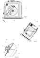
Fig. 3 eine Ansicht von oben auf die Bestandteile des Gargeräts mit einer Schnittmarkierung; -
Fig. 4 die Schnittzeichnung gemäss der Markierung inFig. 3 , wobei der Garraum, die Kamera und die Blickrichtung der Kamera in den Garraum gut sichtbar sind; -
Fig. 4a einen vergrösserten Bildausschnitt der montierten Kamera aus derFig. 4 ; und -
Fig. 5 einen vertikalen Schnitt an der Position der Kamera mit Blick von vorne auf das Gargerät. - Die
Fig. 1, 2 und 2a zeigen wesentliche Bestandteile eines Gargeräts. Beim gezeigten Gargerät handelt es sich um einen sogenannten Combi-Steamer. Dieser kombiniert Dampffunktionen und Heissluft, wobei diese Kombination zu einem sehr guten Garergebnis führt. Die Heissluft sorgt für eine gute Hitze, während der Dampf ein geeignetes Klima generiert. Das Gargut trocknet nicht aus und erhält eine goldbraune Oberfläche. - Das Gargerät umfasst ein Garraumgehäuse 1 (auch Muffel genannt), welches mittels eines Tiefziehverfahrens hergestellt wurde. Das Garraumgehäuse 1 bildet den Garraum 2 und eine Garrauminnenwand 3, welche den Garraum 2 gegen aussen abgrenzt. Die Garrauminnenwand 3 umfasst einen Garraumboden 31, eine Garraumdecke 32, eine Garraumrückwand 33 (siehe
Fig. 4 ) und Garraumseitenwände 34. - Das Gargerät umfasst zudem verschiedenste Heizvorrichtungen 4. An der Unterseite des Garraumgehäuses ist eine Unterhitze-Heizvorrichtung 41 vorhanden. An der Rückseite des Gargeräts ist eine Umluft-Heizvorrichtung 42 (siehe
Fig. 4 ) mit einem Heizkörper und einem Lüfter angeordnet. Nicht gezeigt ist eine Heizvorrichtung zur Generierung des Dampfes. - Im Weiteren wird auch auf die
Fig. 3 bis 5 Bezug genommen. An der Garraumdecke 32 ist eine Öffnung 5 vorhanden. Hinter der Öffnung 5, d.h. oberhalb der Garraumdecke 32, befindet sich eine Kameranische 6, welche Definitionsgemäss nicht Bestandteil des Garraums 2 ist. Eine Kamera 7 ist teilweise oberhalb der Garraumdecke 32 innerhalb der Kameranische 6 und teilweise unterhalb der Garraumdecke 32 im Garraum 2 angeordnet. Dies wird anhand derFig. 5 gut illustriert. - Die Kamera 7 umfasst einen Bildsensor 71, ein Objektiv 72 mit Linsen, eine Frontscheibe 73 und einen Luftraum 74 zwischen dem Objektiv 72 und der Frontscheibe 73 (siehe
Fig. 4a ). Die Frontscheibe 73 und der Luftraum 74 isolieren das Objektiv 72 und den Bildsensor 71 vor Wärme und Schmutz aus dem Garraum 2. - Die Öffnung 5 an der Garraumdecke 32 weist eine Ovalform auf (siehe Fig. 2b) und verschliesst die Verbindung zwischen der Kameranische 6 und dem Garraum 2 nicht. D.h. im Garraum 2 entstehende Dünste können ungehindert durch die Öffnung 5 in die Kameranische 6 eindringen. Zudem ist in
Fig. 5 sichtbar, dass die Kameranische 6 die Form eines stumpfen, schiefen Kegels aufweist. Die Wände der Kameranische 6, welche die Form des stumpfen, schiefen Kegels bilden, sind mit der Bezugsziffer 61 markiert. - Die Blickrichtung 75 der Kamera 7 ist schräg zur Vertikalen 8 mit einem Winkel 9 von 25°. Für eine gute Übersicht des Garraums 2 ist die Kamera 7 deshalb zur Mitte 9 der Garraumdecke 32 (siehe
Fig. 3 ) beabstandet angeordnet. Der Abstand 10 (gestrichelte Line inFig. 3 ) zwischen der Mitte 9 der Garraumdecke 32 und der Kamera 7 beträgt ca. 22 cm. Aufgrund der schrägen Blickrichtung 75, welche von einer seitlichen Anordnung der Kamera 7 ausgeht, lassen sich im Garraum 2 angeordnete Gargüter besonders gut beobachten. Die Gargüter sind bei diesem Blickwinkel 9 sowohl teilweise von oben, als auch teilweise von der Seite sichtbar. - In der
Fig. 5 ist gut erkennbar, dass ein unterer Teil 76 der Kamera 7 innerhalb des Garraums 2 und unterhalb der Garraumdecke 32 angeordnet ist. Ein oberer Teil 77 der Kamera 7 ist innerhalb der Kameranische 6 und somit oberhalb der Garraumdecke 32 angeordnet. Definitionsgemäss ist der obere Teil 77 der Kamera 7 nicht im Garraum 2, sondern in der Kameranische 6 angeordnet. Der obere Teil 77 ist im Verhältnis zur gesamten Kamera 7 deutlich grösser, wie der untere Teil 77. In vertikaler Richtung ragt die Kamera um ca. 1.5 cm in den Garraum 2 hinein. Diese vertikale Distanz von ca. 1.5 cm ist mittels der Bezugsziffer 78 markiert. Sie reicht von der Garraumdecke 32 bis an das untere Ende der Kamera 7. Zudem ist die Frontscheibe 73 teilweise unterhalb der Garraumdecke 32 und teilweise oberhalb der Garraumdecke 32 angeordnet. - Auf der Höhe der Kameranische 7 und somit die Kameranische 7 umgebend, zudem oberhalb der Garraumdecke 32 und an die Garraumdecke 32 direkt angrenzend ist eine Isolationsschicht 11 angeordnet. Diese isoliert den Garraum 2 gegen aussen, sodass die im Garraum 2 erzeugte Wärme möglichst innerhalb des Garraums 2 verbleibt und nicht nach aussen dringt. Die Kameranische 6 und die Kamera 7 überragen die Isolationsschicht 11 nach oben nicht, d.h. die Kameranische 6 und die Kamera 7 sind ausschliesslich unterhalb der oberen Abgrenzung 12 der Isolationsschicht 11 angeordnet.
- Die obere Abgrenzung 12 liegt zwischen der Isolationsschicht 11 und einem oberhalb der Isolationsschicht 12 angeordneten Elektronikraum 13. Im Elektronikraum 13 sind die Steuerung des Gargeräts und weitere elektronische Komponenten (nicht gezeigt) angeordnet. Weder die Kameranische 6, noch die Kamera 7 ragen in den Elektronikraum 13 hinein.
- Während in der vorliegenden Anmeldung bevorzugte Ausführungen der Erfindung beschrieben sind, ist klar darauf hinzuweisen, dass die Erfindung nicht auf diese beschränkt ist und in auch anderer Weise innerhalb des Umfangs der folgenden Ansprüche ausgeführt werden kann.
Claims (10)
- Gargerät, insbesondere ein Haushaltsbackofen, umfassend- einen Garraum (2) mit einer Garrauminnenwand (3), wobei die Garrauminnenwand (3) umfasst einen Garraumboden (31), eine Garraumdecke (32), eine Garraumrückwand (33) und Garraumseitenwände (34),- eine Heizvorrichtung (4),- eine Kamera (7) zur Überwachung des Garraums (2),dadurch gekennzeichnet, dass die Kamera (7) zumindest teilweise oberhalb der Garraumdecke (32) angeordnet ist.
- Gargerät nach einem der vorangehenden Ansprüche, wobei die Kamera (7) teilweise unterhalb der Garraumdecke (32) innerhalb des Garraums (2) angeordnet ist.
- Gargerät nach einem der vorangehenden Ansprüche, wobei die Garraumdecke (32) eine Öffnung (5) aufweist und oberhalb der Garraumdecke (32) und an die Öffnung (5) angrenzend eine Kameranische (6) angeordnet ist, wobei die Kamera (7) teilweise innerhalb der Kameranische (6) angeordnet ist.
- Gargerät nach Anspruch 3, wobei die Öffnung (5) eine Kreis-, eine Oval- oder eine Rechteckform aufweist und die Kameranische (6) die Form eines schiefen, stumpfen, Kreiskegels aufweist.
- Gargerät nach einem der Ansprüche 3 oder 4, wobei die Kameranische (6) offen mit dem Garraum (2) verbunden ist.
- Gargerät nach einem der Ansprüche 3 bis 5, wobei oberhalb der Garraumdecke (32) und unmittelbar an die Garraumdecke (32) angrenzend eine Isolationsschicht (11) vorhanden ist, wobei die Kameranische (6) innerhalb der Isolationsschicht (11) angeordnet ist und wobei die Kameranische (6) die Isolationsschicht (11) nach oben nicht überragt.
- Gargerät nach einem der Ansprüche 3 bis 5, wobei oberhalb der Garraumdecke (32) und unmittelbar an die Garraumdecke (32) angrenzend eine Isolationsschicht (11) vorhanden ist, oberhalb der Isolationsschicht (11) ein Elektronikraum (13) mit Steuerelektronik angeordnet ist, wobei die Kameranische (6) vollständig unterhalb des Elektronikraums (13) innerhalb der Isolationsschicht (11) angeordnet ist.
- Gargerät nach einem der vorangehenden Ansprüche, wobei die Kamera (7) eine Frontscheibe (73) aufweist und die Frontscheibe (73) teilweise unterhalb der Garraumdecke (32) und teilweise oberhalb der Garraumdecke (32) angeordnet ist.
- Gargerät nach einem der vorangehenden Ansprüche, wobei die Blickrichtung (75) der Kamera zur Vertikalen (8) schräg gerichtet ist,und insbesondere zur Horizontalen schräg gerichtet ist,und insbesondere zur Mitte (9) der Garraumdecke (32) beabstandet ist, insbesondere mindestens 5 cm, insbesondere mindestens 10 cm, zur Mitte (9) der Garraumdecke (32) beabstandet ist.
- Gargerät nach einem der vorangehenden Ansprüche, wobei die Kamera (7) in vertikaler Richtung (8) mit einer Länge (78) von maximal 3 cm, insbesondere von maximal 2 cm, unterhalb der Garraumdecke (32) in den Garraum (2) ragt.
Applications Claiming Priority (1)
| Application Number | Priority Date | Filing Date | Title |
|---|---|---|---|
| CH000206/2023A CH720563A1 (de) | 2023-02-28 | 2023-02-28 | Gargerät mit einer Kamera zur Überwachung des Garraums |
Publications (1)
| Publication Number | Publication Date |
|---|---|
| EP4425052A1 true EP4425052A1 (de) | 2024-09-04 |
Family
ID=89535753
Family Applications (1)
| Application Number | Title | Priority Date | Filing Date |
|---|---|---|---|
| EP24150653.4A Pending EP4425052A1 (de) | 2023-02-28 | 2024-01-08 | Gargerät mit einer kamera zur überwachung des garraums |
Country Status (3)
| Country | Link |
|---|---|
| US (1) | US20240288176A1 (de) |
| EP (1) | EP4425052A1 (de) |
| CH (1) | CH720563A1 (de) |
Citations (5)
| Publication number | Priority date | Publication date | Assignee | Title |
|---|---|---|---|---|
| EP3290808A1 (de) * | 2016-09-01 | 2018-03-07 | Samsung Electronics Co., Ltd. | Ofen |
| US20200166276A1 (en) * | 2018-11-28 | 2020-05-28 | Whirlpool Corporation | Cooking appliance |
| EP3786527A1 (de) * | 2018-04-27 | 2021-03-03 | Panasonic Intellectual Property Management Co., Ltd. | Heiz- und kochvorrichtung |
| DE102021100048A1 (de) * | 2021-01-05 | 2022-07-07 | Miele & Cie. Kg | Gargerät mit einer Kamera und Verfahren zu dessen Betrieb |
| WO2022218775A1 (de) * | 2021-04-12 | 2022-10-20 | Miele & Cie. Kg | Verfahren zum betreiben eines gargeräts und gargerät |
Family Cites Families (2)
| Publication number | Priority date | Publication date | Assignee | Title |
|---|---|---|---|---|
| EP3667172A1 (de) * | 2018-12-12 | 2020-06-17 | Electrolux Appliances Aktiebolag | Backofen mit kamera |
| CH717980A1 (de) * | 2020-10-19 | 2022-04-29 | V Zug Ag | Gargerät mit Kamera zur Überwachung des Garraums. |
-
2023
- 2023-02-28 CH CH000206/2023A patent/CH720563A1/de unknown
-
2024
- 2024-01-08 EP EP24150653.4A patent/EP4425052A1/de active Pending
- 2024-01-24 US US18/420,876 patent/US20240288176A1/en active Pending
Patent Citations (5)
| Publication number | Priority date | Publication date | Assignee | Title |
|---|---|---|---|---|
| EP3290808A1 (de) * | 2016-09-01 | 2018-03-07 | Samsung Electronics Co., Ltd. | Ofen |
| EP3786527A1 (de) * | 2018-04-27 | 2021-03-03 | Panasonic Intellectual Property Management Co., Ltd. | Heiz- und kochvorrichtung |
| US20200166276A1 (en) * | 2018-11-28 | 2020-05-28 | Whirlpool Corporation | Cooking appliance |
| DE102021100048A1 (de) * | 2021-01-05 | 2022-07-07 | Miele & Cie. Kg | Gargerät mit einer Kamera und Verfahren zu dessen Betrieb |
| WO2022218775A1 (de) * | 2021-04-12 | 2022-10-20 | Miele & Cie. Kg | Verfahren zum betreiben eines gargeräts und gargerät |
Also Published As
| Publication number | Publication date |
|---|---|
| US20240288176A1 (en) | 2024-08-29 |
| CH720563A1 (de) | 2024-09-13 |
Similar Documents
| Publication | Publication Date | Title |
|---|---|---|
| EP2515044A1 (de) | Garsystem | |
| DE2950946A1 (de) | Backofen | |
| DE102019210976B4 (de) | Kochfeldsystem | |
| DE2533539A1 (de) | Herdtuer-kuehlsystem | |
| EP0856702A1 (de) | Gaskochgerät | |
| EP3985310A1 (de) | Gargerät mit kamera zur überwachung des garraums | |
| DE102004020181C5 (de) | Gewerbliches Gargerät, insbesondere Heißluftdämpfer | |
| EP4425052A1 (de) | Gargerät mit einer kamera zur überwachung des garraums | |
| EP0671591A1 (de) | Vorrichtung zum Abführen von Wrasen aus einem Backofen | |
| DE2949816A1 (de) | Haushalts-gasbackofen mit zwei kammern | |
| CH647587A5 (en) | Device for baking and roasting | |
| DE102016124312A1 (de) | Gargerät mit einer Kamera | |
| DE19649047C2 (de) | Haushaltsgerät mit einer Bedienblende, die mit von vorne nicht sichtbaren Befestigungselementen befestigt ist | |
| DE10219348B4 (de) | Gargerät | |
| EP2444738B1 (de) | Gargerät mit einem Backofen | |
| DE60206822T2 (de) | Elektrischer Haushaltofen für den Einbau | |
| DE202016002911U1 (de) | Zusatzanordnung für ein pfannenartiges Kochgerät | |
| EP0940631A1 (de) | Gargerät mit pyrolytischer Selbstreinigung | |
| DE8905998U1 (de) | Gargerät | |
| EP2390581B1 (de) | Gargerät | |
| EP4053459A1 (de) | Einbaugargerät | |
| EP3708911A1 (de) | Gargerät, umfassend einen garraum und eine kamera zur erstellung von innenaufnahmen des garraums | |
| BE1029171B1 (de) | Einbaugargerät | |
| DE2705983A1 (de) | Mikrowellendichtung fuer kocheinrichtungen | |
| BE1029164A1 (de) | Einbauküchengerät |
Legal Events
| Date | Code | Title | Description |
|---|---|---|---|
| PUAI | Public reference made under article 153(3) epc to a published international application that has entered the european phase |
Free format text: ORIGINAL CODE: 0009012 |
|
| STAA | Information on the status of an ep patent application or granted ep patent |
Free format text: STATUS: THE APPLICATION HAS BEEN PUBLISHED |
|
| AK | Designated contracting states |
Kind code of ref document: A1 Designated state(s): AL AT BE BG CH CY CZ DE DK EE ES FI FR GB GR HR HU IE IS IT LI LT LU LV MC ME MK MT NL NO PL PT RO RS SE SI SK SM TR |
|
| STAA | Information on the status of an ep patent application or granted ep patent |
Free format text: STATUS: REQUEST FOR EXAMINATION WAS MADE |
|
| 17P | Request for examination filed |
Effective date: 20241227 |