EP4425251A1 - Procédé et appareil d'étalonnage pour dispositif électrochromique, et dispositif électrochromique - Google Patents
Procédé et appareil d'étalonnage pour dispositif électrochromique, et dispositif électrochromique Download PDFInfo
- Publication number
- EP4425251A1 EP4425251A1 EP22885828.8A EP22885828A EP4425251A1 EP 4425251 A1 EP4425251 A1 EP 4425251A1 EP 22885828 A EP22885828 A EP 22885828A EP 4425251 A1 EP4425251 A1 EP 4425251A1
- Authority
- EP
- European Patent Office
- Prior art keywords
- electrochromic device
- capacity
- gear
- current
- calibration
- Prior art date
- Legal status (The legal status is an assumption and is not a legal conclusion. Google has not performed a legal analysis and makes no representation as to the accuracy of the status listed.)
- Pending
Links
Images


Classifications
-
- G—PHYSICS
- G02—OPTICS
- G02F—OPTICAL DEVICES OR ARRANGEMENTS FOR THE CONTROL OF LIGHT BY MODIFICATION OF THE OPTICAL PROPERTIES OF THE MEDIA OF THE ELEMENTS INVOLVED THEREIN; NON-LINEAR OPTICS; FREQUENCY-CHANGING OF LIGHT; OPTICAL LOGIC ELEMENTS; OPTICAL ANALOGUE/DIGITAL CONVERTERS
- G02F1/00—Devices or arrangements for the control of the intensity, colour, phase, polarisation or direction of light arriving from an independent light source, e.g. switching, gating or modulating; Non-linear optics
- G02F1/01—Devices or arrangements for the control of the intensity, colour, phase, polarisation or direction of light arriving from an independent light source, e.g. switching, gating or modulating; Non-linear optics for the control of the intensity, phase, polarisation or colour
- G02F1/15—Devices or arrangements for the control of the intensity, colour, phase, polarisation or direction of light arriving from an independent light source, e.g. switching, gating or modulating; Non-linear optics for the control of the intensity, phase, polarisation or colour based on an electrochromic effect
- G02F1/163—Operation of electrochromic cells, e.g. electrodeposition cells; Circuit arrangements therefor
-
- G—PHYSICS
- G01—MEASURING; TESTING
- G01D—MEASURING NOT SPECIALLY ADAPTED FOR A SPECIFIC VARIABLE; ARRANGEMENTS FOR MEASURING TWO OR MORE VARIABLES NOT COVERED IN A SINGLE OTHER SUBCLASS; TARIFF METERING APPARATUS; MEASURING OR TESTING NOT OTHERWISE PROVIDED FOR
- G01D7/00—Indicating measured values
- G01D7/005—Indication of measured value by colour change
-
- G—PHYSICS
- G01—MEASURING; TESTING
- G01R—MEASURING ELECTRIC VARIABLES; MEASURING MAGNETIC VARIABLES
- G01R31/00—Arrangements for testing electric properties; Arrangements for locating electric faults; Arrangements for electrical testing characterised by what is being tested not provided for elsewhere
- G01R31/36—Arrangements for testing, measuring or monitoring the electrical condition of accumulators or electric batteries, e.g. capacity or state of charge [SoC]
-
- G—PHYSICS
- G02—OPTICS
- G02F—OPTICAL DEVICES OR ARRANGEMENTS FOR THE CONTROL OF LIGHT BY MODIFICATION OF THE OPTICAL PROPERTIES OF THE MEDIA OF THE ELEMENTS INVOLVED THEREIN; NON-LINEAR OPTICS; FREQUENCY-CHANGING OF LIGHT; OPTICAL LOGIC ELEMENTS; OPTICAL ANALOGUE/DIGITAL CONVERTERS
- G02F2203/00—Function characteristic
- G02F2203/69—Arrangements or methods for testing or calibrating a device
Definitions
- the present application relates to the field of electrochromic technology, in particular, a calibration method and apparatus for an electrochromic device, and an electrochromic device.
- an electrochromic device is generally divided into different gears according to transmittances, then a series of open circuit voltages (that is, OCV) corresponding to the gears are obtained via test experiments, and then gear shift of the device is controlled according to the OCV.
- OCV open circuit voltage
- light transmittance may have better accuracy when the device is in the early stage of use or when the environment is suitable.
- the corresponding relationship between the OCV and the transmittances of the electrochromic device changes, leading to the inability to accurately adjust the transmittances of the device according to the pre-stored OCV relationship and affecting users' use.
- Embodiments of the present application provide a calibration method and apparatus for an electrochromic device, and an electrochromic device.
- the method can achieve an accurate adjustment of the electrochromic device in different state environments via self-calibration control and can also avoid overcharge and over-discharge of the device which affect the performance of the device.
- inventions of the present application provide a calibration method for an electrochromic device.
- the calibration method may include:
- the electrochromic device is triggered to enter the self-calibration mode when any one or a combination of the following triggering conditions is satisfied: when a total number of gear shifts reaches a preset number threshold; when a time interval from a last calibration reaches a preset time threshold; when a use time of the electrochromic device reaches a preset use time threshold; when a current gear shift operation is not completed when a maximum gear shift duration is exceeded; and when a difference between an open circuit voltage after completion of a current gear shift and an open circuit voltage corresponding to a target gear is not within a preset voltage difference range.
- determining the current total capacity of the electrochromic device may include:
- the calibration method may further include: according to a smaller value of the full charge capacity and the full discharge capacity obtained from an initial test of the electrochromic device, using a full charge test process or a full discharge test process corresponding to the smaller value as a test process for subsequently determining the current total capacity of the electrochromic device.
- the predetermined capacity distribution ratio and an initial corresponding relationship between each gear and the capacity of the electrochromic device may be obtained in advance in the following manners:
- the predetermined capacity distribution ratio and an initial corresponding relationship between each gear and the capacity of the electrochromic device may also be obtained in advance in the following manners:
- the predetermined capacity distribution ratio and an initial corresponding relationship between each gear and the capacity of the electrochromic device may also be obtained in advance in the following manners:
- the calibration method may further include: after the latest total capacity is determined, updating the corresponding relationship between the each gear of the electrochromic device and the capacity of the electrochromic device for a subsequent gear shift operation.
- the electrochromic device may store a plurality of temperature ranges for dividing temperature values, the plurality of temperature ranges comprise an extreme temperature range, a normal temperature range, and an intermediate temperature range other than the normal temperature range and the extreme temperature range, and after the self-calibration mode is entered, the method may further include:
- control method may include:
- inventions of the present application provide a calibration apparatus for an electrochromic device.
- the calibration apparatus may include:
- the calibration apparatus may further include:
- the measurement module may be configured to may be configured to perform capacity distribution on the each gear according to a number of gears of the electrochromic device and based on a set capacity distribution ratio to obtain a capacity corresponding to the each gear; and charge and discharge the electrochromic device, monitor current capacities of the electrochromic device, and in response to the monitored current capacities being separately equal to distributed capacities, record a corresponding open circuit voltages to obtain an initial corresponding relationship among the each gear of the electrochromic device, an open circuit voltage of the electrochromic device, and the capacity of the electrochromic device.
- the determination module may include:
- inventions of the present application provide an electrochromic device.
- the electrochromic device may include a processor and a memory, where the memory stores a computer program, and the processor is configured to execute the computer program to implement the calibration or the control method described above.
- embodiments of the present application provide a readable storage medium storing a computer program which, when executed by a processor, implements the calibration or control method described above.
- a self-calibration mode is entered when a triggering condition is satisfied, the current total capacity of the electrochromic device is determined, and the total capacity is updated when a large deviation exists between the current total capacity and the total capacity stored last time. Meanwhile, the corresponding relationship between each gear and the capacity is re-determined in combination with a predetermined capacity distribution ratio for subsequent gear shifts.
- the method can achieve an accurate adjustment of the electrochromic device in different state environments, improve the user experience, and can also avoid overcharge and over-discharge of the device which affect the performance of the device.
- the gear shift and control is usually performed according to the OCV value corresponding to each gear of an electrochromic device.
- Table 1 shows the corresponding relationships among the transmittances, OCV, and gears of an electrochromic device tested before and after aging.
- Table 1 Gear 1 2 3 4 5 Transmittance 1% 5% 10% 20% 40% OCV (before aging) -0.7V -0.5V 0 0.5V 0.7V OCV (after aging) unreachable -0.7V 0 0.7V 0.9V
- the device is always charged and discharged by the power supply until the gear is reached.
- the device cannot reach -0.7 V. Therefore, the device is still charged and discharged, and such a long-time overcharge and over-discharge may cause irreversible damage to the device.
- an embodiment of the present application provides a calibration method for an electrochromic device.
- the corresponding relationship among each gear, the corresponding capacity and OCV of an electrochromic device may be continuously updated by regular or irregular self-calibration of the device to obtain the latest state of the electrochromic device.
- the gear shift control is achieved by using the newly updated preceding corresponding relationship so that the accurate color change adjustment of the device can be achieved in different states, and the service life can be improved as much as possible on the premise of meeting user needs.
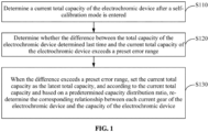
- FIG. 1 shows a first flowchart of a calibration method for an electrochromic device according to an embodiment of the present application.
- the calibration method for an electrochromic device includes S110 to S130.
- S110 A current total capacity of the electrochromic device is determined after a self-calibration mode is entered.
- the self-calibration mode refers to a state mode where the electrochromic device performs the self-calibration.
- the electrochromic device stops shifting gears and performs calibration-related operations, and allows a gear shift operation only after the calibration operations are completed. For example, when it is detected that certain triggering conditions are satisfied, the process of self-calibration is started, and at this time it can be considered that the preceding self-calibration mode is entered.
- the electrochromic device may be triggered to enter the self-calibration mode when any of the following triggering conditions is satisfied.
- triggering conditions for entering the self-calibration mode may include, but are not limited to one or more combinations of the following: when the total number of gear shifts accumulated by the device reaches a preset number threshold; when the time interval from the last calibration reaches a preset time threshold; and when the use time of the device reaches a preset use time threshold.
- the triggering conditions enumerated above may be divided into determinate triggering conditions. Additionally, the triggering condition may also include indeterminate triggering conditions. For example, an entry into the self-calibration mode may also be triggered when an abnormality occurs in the gear shift operation.
- the indeterminate triggering conditions also include, but are not limited to one or a combination of the following: when the current gear shift operation is not completed when the maximum gear shift duration is exceeded, that is, a gear shift timeout occurs; when the difference between an open circuit voltage after completion of the current gear shift and an open circuit voltage corresponding to the target gear is not within a preset voltage difference range.
- the total capacity of the electrochromic device varies with the state of the material due to the characteristics of the electrochromic material.
- the gear shift operation is completed mainly based on the capacity, and the OCV corresponding to each gear may also be used to verify the accuracy after the gear shift.
- the current total capacity of the electrochromic device is re-determined, and then the total capacity is used for updating the corresponding relationship between each gear and the capacity of the electrochromic device.
- a full charge state when the device is fully charged and a full discharge state when the device is fully discharged.
- the charge capacity required from the full discharge state to the full charge state is defined as a full charge capacity Q1.
- the charge capacity required from the full charge state to the full discharge state is defined as a full discharge capacity Q2.
- the charge or discharge current gradually tends to be zero. Since it takes a long time to reach the completely zero current, a cutoff current close to zero is configured in this embodiment to reduce the waiting time of users. When it is detected that the charge or discharge current is less than or equal to the cutoff current, it can be considered that the device reaches the full charge state or the full discharge state.
- the current device may be discharged and the discharge current is detected in real time until the discharge current is less than or equal to a preset cutoff current, that is, after the full discharge state is reached, the device is charged until the charge current is less than or equal to the preset cutoff current, that is, when the full charge state is reached, and the full charge capacity Q1 required by the device from being fully discharged to being fully charged is recorded. At this time, the fully charge capacity is used as the current total capacity of the device.
- the full discharge capacity Q2 required from the full charge state to the full discharge state may be used as the current total capacity of the electrochromic device.
- the current device may be charged first and the charge current is detected in real time until the charge current is less than or equal to the preset cutoff current, that is, when the full charge state is reached, charging is stopped and the device is discharged until the discharge current is less than or equal to the present cutoff current, that is, when the full discharge state is reached, and the full discharge capacity Q2 required by the device from being fully charged to being fully discharged is recorded. At this time, the full discharge capacity is used as the current total capacity of the device.
- the full charge capacity Q1 and the full discharge capacity Q2 of the device are first measured, and the smaller value of the two is used as the original total capacity of the device.
- the full charge test process or the full discharge test process corresponding to the smaller value is used as the test process for subsequently determining the current total capacity of the electrochromic device.
- the full charge capacity is used as the total capacity
- the current full charge capacity is determined according to the test process of fully discharging first and then fully charging when self-calibration is performed subsequently.
- the reversibility of the electrochromic material affects the relationship between the full charge capacity Q1 and the full discharge capacity Q2 so that the full charge capacity Q1 is not necessarily the same as the full discharge capacity Q2.
- S120 It is determined whether the difference between a total capacity of the electrochromic device determined last time and the current total capacity of the electrochromic device exceeds a preset error range.
- the current total capacity is acquired by using S110, it may be determined whether the absolute value of the difference between the total capacity determined last time and the current total capacity is greater than or equal to a preset ratio of the total capacity determined last time, such as 0.3% to 0.6%, etc., which may be adjusted adaptively according to actual needs. If the absolute value is greater than or equal to the preset ratio, it indicates that the current state of the device may have changed to some extent from before. Therefore, S130 may be performed to ensure the accuracy of subsequent gear shifts and adjustments.
- a preset ratio of the total capacity determined last time such as 0.3% to 0.6%, etc.
- the total capacity determined last time may be maintained, that is, the value of the total capacity is not updated, and in this case, the self-calibration mode may be exited and a shift signal is waited for.
- the preceding total capacity determined last time may refer to the original total capacity obtained by testing of the device at the time of leaving the factory or may refer to the latest total capacity re-determined after the device performs a corresponding self-calibration.
- the preceding predetermined capacity distribution ratio refers to the ratio of the capacity corresponding to each gear to the total capacity, which may be obtained by debugging before leaving the factory. In subsequent operations, the distribution ratio continues to be used, and the corresponding relationship between each gear and the capacity is updated only by updating the value of the total capacity during self-calibration. It can be understood that the device in this embodiment stores the preceding capacity distribution ratio information and the initial corresponding relationship among each gear, the open circuit voltage, and the capacity of the device before leaving the factory for performing subsequent gear shift and control.
- the predetermined capacity distribution ratio and the initial corresponding relationship between each gear of the electrochromic device and the capacity of the electrochromic device may be obtained in the manner where the capacity and OCV corresponding to each gear are determined first, and then the capacity distribution ratio is determined.
- the specific manner is as follows:
- the electrochromic device is charged and discharged, and corresponding open circuit voltages and capacities of the electrochromic device are measured at different transmittances to obtain the initial corresponding relationship among each gear of the electrochromic device, the open circuit voltage of the electrochromic device, and the capacity of the electrochromic device. Different transmittances correspond to different gears.
- the capacity distribution ratio corresponding to each gear of the electrochromic device may be obtained according to the ratio of the measured capacity corresponding to each gear to the total capacity of the electrochromic device at the corresponding measurement stage which is usually the ratio of the capacity corresponding to each gear to the original total capacity at the time of leaving the factory.
- Table 2 the initial corresponding relationship among six gears of an electrochromic device, the OCV of the electrochromic device, and the capacity of the electrochromic device is described in Table 2 below.
- Table 2 Gear 1 2 3 4 5 6 Transmittance 1% 5% 10% 20% 40% 60% OCV -0.7V -0.5V 0 0.5V 0.7V 0.9V Capacity 0 0.05Q 0.2Q 0.35Q 0.65Q Q
- the predetermined capacity distribution ratio and the initial corresponding relationship between each gear of the electrochromic device and the capacity of the electrochromic device may also be obtained in the manner where the capacity distribution ratio is determined first, and then the capacity and OCV corresponding to each gear are determined.
- the specific manner is as follows:
- function fitting may be used for determining the initial corresponding relationship among each gear, the open circuit voltage, and the capacity.
- capacities corresponding to part gears may be selected for testing such as at least four gears so that it is not necessary to test all the gears. In this manner, when many gears are provided, the workload of detection and the error in gear measurement can be greatly reduced.
- the current corresponding relationship between each gear of the electrochromic device and the capacity of the electrochromic device is updated.
- the corresponding relationship stored in Table 2 is used as an example.
- the total capacity Q in Table 2 may be updated to Q', and at this time, the capacity value corresponding to each gear changes, and a new corresponding relationship between each gear and the capacity is able to be obtained.
- the subsequent gear shift operation may be performed using the updated corresponding relationship.
- the current gear of the device may be identified according to the current OCV, and then charge or discharge is controlled according to the capacity difference between the current gear and the target gear to switch to the target gear.
- a self-calibration mode is entered when a triggering condition is satisfied, the current total capacity of the electrochromic device is determined, and the total capacity is updated when a large deviation exists between the current total capacity and the total capacity stored last time. Meanwhile, the corresponding relationship between each gear and the capacity is re-determined in combination with a predetermined capacity distribution ratio for subsequent gear shifts.
- the method can achieve an accurate adjustment of the electrochromic device in different state environments, improve the user experience, and avoid overcharge and over-discharge of the device which affect the performance of the device.
- this embodiment proposes a calibration method for an electrochromic device. This method differs from the method of the embodiment described above in that the current corresponding relationship among each gear, the capacity, and the OCV of the electrochromic device is re-determined in this embodiment, that is, the capacity and OCV corresponding to each gear are updated at the same time.
- the calibration method for an electrochromic device includes the steps described below.
- S210 A current total capacity of the electrochromic device is determined after a self-calibration mode is entered.
- S210 and S220 may refer to S110 and S120 described above, and the description is not repeated herein.
- the electrochromic device is charged with a charge capacity of a preset distribution ratio each time according to the preset number of charging times, a preset period is waited for after charging, and a current open circuit voltage of the electrochromic device is measured and recorded after each charge to obtain multiple sets of measurement data of a capacity and a corresponding open circuit voltage of the electrochromic device.
- the preset number of charging times in this embodiment should be greater than or equal to 3, which, together with one measurement before the capacity is charged, it is ensured that at least four sets of measurement data are obtained, satisfying the data requirement of function fitting.
- the preset distribution ratio may be configured according to the preset number of charging times. For example, the preset number of charging times is used as an example. When the number of charging times is 3, the device may be charged with a capacity of Q/3 each time. Additionally, configuration may be made according to the capacity distribution ratio corresponding to each gear. For example, when the number of gears is 5, and the capacity ratio of the gears is evenly distributed, the device may be charged 4 times with a capacity of Q/4 each charge. In this manner, five sets of measurement data including capacities and corresponding open circuit voltages of different gears are obtained.
- the current open circuit voltage may be measured after a preset period and denoted as OCV (0), and then one is added to i; then the device is charged once according to the corresponding distribution ratio, and after another preset period, the open circuit voltage after the current charge is read and denoted as OCV (1); such a step is repeated until i is equal to the preset number of charging times; multiple sets of measurement data are obtained by recording the open circuit voltage after the corresponding capacity is charged each time.
- S240 The multiple sets of measurement data are fitted to obtain a functional relationship between the current capacities and open circuit voltages of the device.
- the multiple sets of measurement data may be fitted by function fitting to obtain a new cubic function expression between the capacity at each gear and the corresponding open circuit voltage. Then, based on the updated total capacity and the known capacity distribution ratio, the corresponding capacity value of each gear may be calculated; then based on this function expression, the OCV corresponding to each capacity may be calculated; and then the relationship among each current gear of the electrochromic device, the capacity of the electrochromic device, and the open circuit voltage of the electrochromic device may be re-determined for subsequent gear shift operations.
- the electrochromic device in this embodiment may store multiple temperature ranges for dividing temperature values in advance, and the multiple temperature ranges include an extreme temperature range, a normal temperature range, and an intermediate temperature range other than the normal temperature range and the extreme temperature range.
- the normal temperature range may be configured to be 0°C to 40°C
- the extreme temperature range may be configured to be below -10°C and above 80°C
- the intermediate temperature range may be configured to be, for example, -10°C to 0°C and 40°C to 80°C, which may also be adjusted according to actual needs, and ranges herein are just examples.
- this embodiment proposes a calibration method for an electrochromic device.
- This method differs from the methods of the embodiments described above in that the preceding two calibration methods are alternately used for self-calibration in this embodiment. Specifically" after the first calibration method of only updating the capacity is performed for a period of time or a certain number of times, the second calibration method of simultaneously updating the capacity and the OCV is performed once, and then the second calibration method is switched to the first calibration method, that is, the two calibration methods are alternatively used.
- the calibration method for an electrochromic device includes the steps described below.
- S310 A current total capacity of the electrochromic device is determined after a self-calibration mode is entered.
- S340 It is detected whether the number of operations for re-determining the corresponding relationship between each current gear of the electrochromic device and the capacity of the electrochromic device according to the current total capacity and based on the predetermined capacity distribution ratio is greater than or equal to the preset number of calibration switching times.
- the first calibration method is switched to the second calibration method for a one-time calibration at the next self-calibration. Then, at the next self-calibration after the next self-calibration, the second calibration method is switched to the first calibration method to perform multiple calibrations. The above is cycled so that the self-calibration operation is continuously performed.
- the one-time self-calibration process in the manner where the relationship among each current gear of the electrochromic device, the capacity of the electrochromic device, and the open circuit voltage of the electrochromic device is re-determined according to the current total capacity and the functional relationship and based on the predetermined capacity distribution ratio is the same as that of S230 to S250 described above, and the description is not repeated herein.
- the method also includes the steps described below after the self-calibration mode is entered in an embodiment.
- S410 The temperature range in which the current ambient temperature of the electrochromic device is located is determined.
- the calibration may be allowed when the current ambient temperature of the electrochromic device is in the intermediate temperature range, but the determined total capacity needs to be adjusted in a certain proportion to ensure the accuracy of the final calibration result.
- a linear relationship exists between the total capacity and the temperature coefficient. Specifically, according to the standard capacity measured at normal temperature and stored in the device, when the ambient temperature is high or low, the total capacity Q determined at this time may be converted to the total capacity Q N at normal temperature according to the linear relationship described above, and the total capacity Q N may be used as the adjusted total capacity determined at this time for subsequent calculation and analysis.
- a method for controlling an electrochromic device is proposed in this embodiment based on the methods described in the preceding embodiments.
- the method for controlling an electrochromic device includes the steps described below.
- the gear shift signal when the gear shift signal is received, the current gear information is identified by comparison of a read OCV with the OCV in the corresponding relationship, which is obtained after self-calibration, between the capacity at each gear and the OCV of the device obtained after self-calibration. It can be understood that since the charge in a device that is not in a charge or discharge state tends to be uniformly distributed, a more accurate OCV value is able to be measured.
- the gear shift signal usually carries information about the target gear so that the gear shift signal may be directly analyzed to obtain the target gear.
- S530 The capacity difference between the target gear and the current gear is calculated according to the latest determined corresponding relationship between each gear of the electrochromic device and the capacity of the electrochromic device.
- S540 The electrochromic device is charged or discharged according to the capacity difference to switch the electrochromic device to the target gear.
- the charge capacities of the target gear and the current gear may be differenced to obtain a capacity difference. If the capacity difference is positive, it indicates that a charge is required; otherwise, a discharge is required. Therefore, the gear shift and adjustment are performed according to the corresponding charge or discharge operation. For example, the adjustment may be performed in a constant voltage or constant current manner, which is not specifically limited.
- a calibration apparatus 100 for an electrochromic device is proposed in this embodiment.
- the calibration apparatus 100 for an electrochromic device includes the modules below.
- a determination module 110 is configured to determine the current total capacity of the electrochromic device after a self-calibration mode is entered.
- a adjustment module 120 is configured to set the current total capacity as the latest total capacity when the difference between the total capacity of the electrochromic device determined last time and the current total capacity of the electrochromic device exceeds a preset error range and re-determine a corresponding relationship between each current gear of the electrochromic device and a capacity of the electrochromic device according to the current total capacity and based on a predetermined capacity distribution ratio.
- the calibration apparatus 100 for an electrochromic device further include the modules below.
- An acquisition module is configured to charge the electrochromic device with a charge capacity of a preset distribution ratio each time according to the preset number of charging times, wait for a preset period after charging, and measure and record a current open circuit voltage of the electrochromic device after each charge to obtain multiple sets of measurement data of a current capacity of the electrochromic device and a corresponding open circuit voltage.
- a fitting module is configured to fit the multiple sets of measurement data to obtain the functional relationship between the capacities and the open circuit voltages.
- the adjustment module 120 is configured to re-determine the relationship among each current gear of the electrochromic device, the capacity of the electrochromic device, and the open circuit voltage of the electrochromic device according to the current total capacity and the functional relationship and based on the predetermined capacity distribution ratio.
- the calibration apparatus 100 for an electrochromic device further include the module below.
- a switch module is configured to, when the number of operations performed by the adjustment module 120 to re-determine the corresponding relationship between each current gear of the electrochromic device and the capacity of the electrochromic device according to the current total capacity and based on the predetermined capacity distribution ratio is greater than or equal to the preset number of calibration switching times, switch to perform a calibration after the self-calibration mode is entered next time and in a manner of re-determining the relationship among each current gear of the electrochromic device, the capacity of the electrochromic device, and the open circuit voltage of the electrochromic device according to the current total capacity and the functional relationship and based on the predetermined capacity distribution ratio.
- the calibration apparatus 100 for an electrochromic device further includes the module below.
- a measurement module is configured to charge and discharge the electrochromic device and measure open circuit voltages and capacities of the electrochromic device at different transmittances to obtain the initial corresponding relationship among each gear of the electrochromic device, the open circuit voltage of the electrochromic device, and the capacity of the electrochromic device, where different transmittances correspond to different gears; then obtain the capacity distribution ratio corresponding to each gear of the electrochromic device according to the ratio of the capacity corresponding to each gear to the total capacity of the electrochromic device at a corresponding measurement stage.
- the measurement module may also be configured to perform capacity distribution on each gear according to the number of gears of the electrochromic device and based on the set capacity distribution ratio to obtain the capacity corresponding to each gear; charge and discharge the electrochromic device, monitor the current capacities of the electrochromic device, and when the monitored current capacities are separately equal to distributed capacities, record corresponding open circuit voltages to obtain the initial corresponding relationship among each gear of the electrochromic device, the open circuit voltage of the electrochromic device, and the capacity of the electrochromic device.
- the determination module 110 includes a charge-discharge control sub-module and a recording sub-module.
- the charge-discharge control sub-module is configured to discharge the electrochromic device until a full discharge state is reached and charge the electrochromic device until a full charge state is reached;
- the recording sub-module is configured to record a full charge capacity required by the electrochromic device from the full discharge state to the full charge state; the full charge capacity is used as the current total capacity of the electrochromic device.
- the charge-discharge control sub-module is configured to charge the electrochromic device until a full charge state is reached and discharge the electrochromic device until a full discharge state is reached;
- the recording sub-module is configured to record a full discharge capacity required by the electrochromic device from the full charge state to the full discharge state; the full discharge capacity is used as the current total capacity of the electrochromic device.
- the determination module 110 is further configured to, after the self-calibration mode is entered and before the current total capacity of the electrochromic device is determined, use a full charge test process or a full discharge test process corresponding to the smaller value as a test process for subsequently determining the current total capacity of the electrochromic device according to the minimum value of the full charge capacity and the full discharge capacity obtained from an initial test of the electrochromic device.
- the electrochromic device stores multiple temperature ranges for dividing temperature values, and the multiple temperature ranges include an extreme temperature range, a normal temperature range, and an intermediate temperature range other than the normal temperature range and the extreme temperature range.
- the calibration apparatus 100 for an electrochromic device also includes a detection module, a stopping module, and an adjustment module.
- the detection module is configured to determine the temperature range in which the current ambient temperature of the electrochromic device is located after the self-calibration mode is entered.
- the stopping module is configured to stop the self-calibration operation if the temperature range in which the current ambient temperature of the electrochromic device is located is in the extreme temperature range.
- the determination module 110 is also configured to perform the step of determining the current total capacity of the electrochromic device if the temperature range in which the current ambient temperature of the electrochromic device is located is in the normal temperature range, while the adjustment module is configured to, if the temperature range in which the current ambient temperature of the electrochromic device is located is in the intermediate temperature range, adjust the determined total capacity according to a preset temperature coefficient after the current total capacity of the electrochromic device is determined by the determination module 110.
- the present application further provides an electrochromic device, which may be, for example, a device integrated with an integrated electrochromic material such as a dimming window, a windshield of an automobile, and the like.
- the electrochromic device includes a processor and a memory.
- the memory stores a computer program.
- the processor by running the computer program, causes a terminal device to perform the preceding methods or functions of each module in the apparatus described above.
- the present application further provides a readable storage medium configured to store the computer program used in the electrochromic device described above.
- each block in a flowchart or block diagram may represent a part of a module, a program segment, or codes.
- the part of the module, the program segment, or codes contains one or more executable instructions for implementing specified logical functions.
- functions noted in the blocks may take an order different from that noted in the drawings.
- the functional modules may be stored in a computer-readable storage medium if implemented in the form of software function modules and sold or used as independent products. Based on this understanding, the technical solutions provided in this application substantially, the part contributing to the existing art, or part of the technical solutions may be embodied in the form of a software product.
- This computer software product is stored in a storage medium including several instructions for enabling a computer device (which may be a smart phone, a personal computer, a server, or a network device, etc.) to perform all or part of the steps in the methods provided in embodiments of this application.
- the preceding storage medium may include a U disk, a mobile hard disk, a read-only memory (ROM, Read-Only Memory), a random-access memory (RAM, Random Access Memory), a magnetic disk, an optical disk, or another medium that can store program codes.
- ROM Read-Only Memory
- RAM Random Access Memory
Landscapes
- Physics & Mathematics (AREA)
- Nonlinear Science (AREA)
- General Physics & Mathematics (AREA)
- Optics & Photonics (AREA)
- Control Of Indicators Other Than Cathode Ray Tubes (AREA)
- Electrochromic Elements, Electrophoresis, Or Variable Reflection Or Absorption Elements (AREA)
Applications Claiming Priority (2)
| Application Number | Priority Date | Filing Date | Title |
|---|---|---|---|
| CN202111260799.4A CN116047827B (zh) | 2021-10-28 | 2021-10-28 | 电致变色器件的校准方法、装置和电致变色器件 |
| PCT/CN2022/126840 WO2023071951A1 (fr) | 2021-10-28 | 2022-10-21 | Procédé et appareil d'étalonnage pour dispositif électrochromique, et dispositif électrochromique |
Publications (2)
| Publication Number | Publication Date |
|---|---|
| EP4425251A1 true EP4425251A1 (fr) | 2024-09-04 |
| EP4425251A4 EP4425251A4 (fr) | 2025-10-08 |
Family
ID=86111934
Family Applications (1)
| Application Number | Title | Priority Date | Filing Date |
|---|---|---|---|
| EP22885828.8A Pending EP4425251A4 (fr) | 2021-10-28 | 2022-10-21 | Procédé et appareil d'étalonnage pour dispositif électrochromique, et dispositif électrochromique |
Country Status (5)
| Country | Link |
|---|---|
| US (1) | US20240272508A1 (fr) |
| EP (1) | EP4425251A4 (fr) |
| JP (1) | JP7729655B2 (fr) |
| CN (1) | CN116047827B (fr) |
| WO (1) | WO2023071951A1 (fr) |
Families Citing this family (5)
| Publication number | Priority date | Publication date | Assignee | Title |
|---|---|---|---|---|
| CN116884363A (zh) * | 2023-07-03 | 2023-10-13 | 深圳和而泰汽车电子科技有限公司 | 电致变色器件的校准方法、控制方法及车辆 |
| CN117031847A (zh) * | 2023-08-21 | 2023-11-10 | 深圳和而泰汽车电子科技有限公司 | 电致变色器件的透光率档位维持方法及车辆 |
| CN120009253A (zh) * | 2023-11-15 | 2025-05-16 | 深圳市光羿科技有限公司 | 电致变色产品的测试方法、系统、电子设备及存储介质 |
| CN117475962A (zh) * | 2023-12-13 | 2024-01-30 | 深圳市光羿科技有限公司 | 一种电致变色器件控制方法、装置、存储介质及控制系统 |
| CN117672157A (zh) * | 2023-12-13 | 2024-03-08 | 深圳市光羿科技有限公司 | 一种电致变色器件控制方法、装置、存储介质及控制系统 |
Family Cites Families (12)
| Publication number | Priority date | Publication date | Assignee | Title |
|---|---|---|---|---|
| FR2728696A1 (fr) * | 1994-12-23 | 1996-06-28 | Saint Gobain Vitrage | Procede d'alimentation electrique d'un vitrage electrocommandable |
| AUPO816097A0 (en) * | 1997-07-22 | 1997-08-14 | Sustainable Technologies Australia Limited | Combined electrochromic and photovoltaic smart window devices and methods |
| US7133181B2 (en) * | 2004-07-23 | 2006-11-07 | Sage Electrochromics, Inc. | Control system for electrochromic devices |
| US9091897B2 (en) * | 2013-03-16 | 2015-07-28 | Tintable Smart Material Co., Ltd. | Transmittance control method of electrochromic component |
| SE539529C2 (en) * | 2016-01-12 | 2017-10-10 | Chromogenics Ab | A method for controlling an electrochromic device and an electrochromic device |
| US11482147B2 (en) * | 2016-04-29 | 2022-10-25 | View, Inc. | Calibration of electrical parameters in optically switchable windows |
| CN110989262B (zh) * | 2019-12-17 | 2022-04-01 | 深圳市光羿科技有限公司 | 电致变色器件的控制方法、装置、设备及存储介质 |
| CN113156730B (zh) * | 2020-01-23 | 2022-07-19 | 青岛凯欧斯光电科技有限公司 | 控制电致变色器件的方法 |
| TWI786524B (zh) * | 2020-01-24 | 2022-12-11 | 美商塞奇電致變色公司 | 用於改善控制精度的電致變色玻璃磁滯補償 |
| CN116909068B (zh) * | 2021-01-06 | 2026-03-17 | 深圳市光羿科技有限公司 | 一种电致变色器件的调控方法及一种电子设备 |
| CN114839819A (zh) * | 2021-02-01 | 2022-08-02 | Oppo广东移动通信有限公司 | 控制方法、电子设备及计算机可读存储介质 |
| CN115157978B (zh) * | 2022-06-24 | 2024-12-06 | 浙江极氪智能科技有限公司 | 一种玻璃透光率的调节方法、装置、设备及存储介质 |
-
2021
- 2021-10-28 CN CN202111260799.4A patent/CN116047827B/zh active Active
-
2022
- 2022-10-21 JP JP2024525117A patent/JP7729655B2/ja active Active
- 2022-10-21 WO PCT/CN2022/126840 patent/WO2023071951A1/fr not_active Ceased
- 2022-10-21 EP EP22885828.8A patent/EP4425251A4/fr active Pending
-
2024
- 2024-04-24 US US18/644,796 patent/US20240272508A1/en active Pending
Also Published As
| Publication number | Publication date |
|---|---|
| CN116047827A (zh) | 2023-05-02 |
| EP4425251A4 (fr) | 2025-10-08 |
| JP7729655B2 (ja) | 2025-08-26 |
| JP2024542987A (ja) | 2024-11-19 |
| CN116047827B (zh) | 2024-04-16 |
| WO2023071951A1 (fr) | 2023-05-04 |
| US20240272508A1 (en) | 2024-08-15 |
Similar Documents
| Publication | Publication Date | Title |
|---|---|---|
| EP4425251A1 (fr) | Procédé et appareil d'étalonnage pour dispositif électrochromique, et dispositif électrochromique | |
| EP4411472A1 (fr) | Procédé et appareil de commande de changement de vitesse pour dispositif électrochromique, et dispositif électrochromique | |
| US10534037B2 (en) | Devices with battery remaining capacity estimating functions | |
| US20230047373A1 (en) | Method and apparatus for battery soc correction, and battery management system | |
| KR102742037B1 (ko) | 절연저항 측정 장치 및 방법 | |
| US12222403B2 (en) | Battery device, detection method thereof, and screening method and device of battery unit | |
| US20240159836A1 (en) | Method and device for calibrating soc at tail end of charging or discharging of energy storage system | |
| CN114441968B (zh) | 电池自放电的监控方法、装置、计算机设备及存储介质 | |
| WO2024021900A1 (fr) | Procédé de commande et système de commande pour dispositif à commutation optique, et dispositif à commutation optique | |
| KR20260014000A (ko) | 조광 가능한 소자의 시프트 제어 방법, 장치, 매체 및 시스템 | |
| CN116626518A (zh) | 一种电池自放电检测方法及系统 | |
| EP3278125B1 (fr) | Appareil et procédés permettant de surveiller une batterie à l'aide de mesures d'impulsion de décharge | |
| CN120820856A (zh) | 充放电多重联合修正的soc估算方法、装置、介质、程序产品及终端 | |
| CN120254675A (zh) | 一种容量校准方法及相关装置 | |
| CN117649830A (zh) | 电致变色器件的工作电压确定方法、系统、设备及介质 | |
| CN115616405A (zh) | 电量计算方法、电量计算装置、电子设备和存储介质 | |
| CN116125309A (zh) | 一种电池开路电压稳定时长的确定方法、装置、电子设备 | |
| CN115113061A (zh) | 修正电池soc的方法及相关装置 | |
| CN120908695B (zh) | Ocv-soc曲线自学习方法、装置、电子设备及介质 | |
| US20250123332A1 (en) | Battery management apparatus and operating method of the same | |
| CN119902105A (zh) | Soc校准方法、系统、控制装置及存储介质 | |
| KR20240091604A (ko) | 배터리 노화상태 추정 장치 및 방법 | |
| WO2025103028A1 (fr) | Procédé et système de test pour produit électrochromique et dispositif électronique et support de stockage | |
| CN120722217A (zh) | 一种电池电量校准方法与系统 | |
| CN120908679A (zh) | 一种电芯soc的估算方法、装置及设备 |
Legal Events
| Date | Code | Title | Description |
|---|---|---|---|
| STAA | Information on the status of an ep patent application or granted ep patent |
Free format text: STATUS: THE INTERNATIONAL PUBLICATION HAS BEEN MADE |
|
| PUAI | Public reference made under article 153(3) epc to a published international application that has entered the european phase |
Free format text: ORIGINAL CODE: 0009012 |
|
| STAA | Information on the status of an ep patent application or granted ep patent |
Free format text: STATUS: REQUEST FOR EXAMINATION WAS MADE |
|
| 17P | Request for examination filed |
Effective date: 20240516 |
|
| AK | Designated contracting states |
Kind code of ref document: A1 Designated state(s): AL AT BE BG CH CY CZ DE DK EE ES FI FR GB GR HR HU IE IS IT LI LT LU LV MC ME MK MT NL NO PL PT RO RS SE SI SK SM TR |
|
| DAV | Request for validation of the european patent (deleted) | ||
| DAX | Request for extension of the european patent (deleted) | ||
| A4 | Supplementary search report drawn up and despatched |
Effective date: 20250909 |
|
| RIC1 | Information provided on ipc code assigned before grant |
Ipc: G02F 1/163 20060101AFI20250903BHEP Ipc: G01R 31/36 20200101ALI20250903BHEP |