EP4425295B1 - Ensemble réducteur de pression - Google Patents
Ensemble réducteur de pression Download PDFInfo
- Publication number
- EP4425295B1 EP4425295B1 EP23159179.3A EP23159179A EP4425295B1 EP 4425295 B1 EP4425295 B1 EP 4425295B1 EP 23159179 A EP23159179 A EP 23159179A EP 4425295 B1 EP4425295 B1 EP 4425295B1
- Authority
- EP
- European Patent Office
- Prior art keywords
- pressure reducer
- piston rod
- reducer assembly
- pressure
- fluid
- Prior art date
- Legal status (The legal status is an assumption and is not a legal conclusion. Google has not performed a legal analysis and makes no representation as to the accuracy of the status listed.)
- Active
Links
Images



Classifications
-
- F—MECHANICAL ENGINEERING; LIGHTING; HEATING; WEAPONS; BLASTING
- F16—ENGINEERING ELEMENTS AND UNITS; GENERAL MEASURES FOR PRODUCING AND MAINTAINING EFFECTIVE FUNCTIONING OF MACHINES OR INSTALLATIONS; THERMAL INSULATION IN GENERAL
- F16K—VALVES; TAPS; COCKS; ACTUATING-FLOATS; DEVICES FOR VENTING OR AERATING
- F16K17/00—Safety valves; Equalising valves, e.g. pressure relief valves
- F16K17/20—Excess-flow valves
- F16K17/22—Excess-flow valves actuated by the difference of pressure between two places in the flow line
- F16K17/24—Excess-flow valves actuated by the difference of pressure between two places in the flow line acting directly on the cutting-off member
- F16K17/28—Excess-flow valves actuated by the difference of pressure between two places in the flow line acting directly on the cutting-off member operating in one direction only
- F16K17/30—Excess-flow valves actuated by the difference of pressure between two places in the flow line acting directly on the cutting-off member operating in one direction only spring-loaded
-
- G—PHYSICS
- G05—CONTROLLING; REGULATING
- G05D—SYSTEMS FOR CONTROLLING OR REGULATING NON-ELECTRIC VARIABLES
- G05D16/00—Control of fluid pressure
- G05D16/04—Control of fluid pressure without auxiliary power
- G05D16/10—Control of fluid pressure without auxiliary power the sensing element being a piston or plunger
- G05D16/103—Control of fluid pressure without auxiliary power the sensing element being a piston or plunger the sensing element placed between the inlet and outlet
-
- F—MECHANICAL ENGINEERING; LIGHTING; HEATING; WEAPONS; BLASTING
- F16—ENGINEERING ELEMENTS AND UNITS; GENERAL MEASURES FOR PRODUCING AND MAINTAINING EFFECTIVE FUNCTIONING OF MACHINES OR INSTALLATIONS; THERMAL INSULATION IN GENERAL
- F16K—VALVES; TAPS; COCKS; ACTUATING-FLOATS; DEVICES FOR VENTING OR AERATING
- F16K1/00—Lift valves or globe valves, i.e. cut-off apparatus with closure members having at least a component of their opening and closing motion perpendicular to the closing faces
- F16K1/32—Details
- F16K1/52—Means for additional adjustment of the rate of flow
- F16K1/523—Means for additional adjustment of the rate of flow for limiting the maximum flow rate, using a stop
-
- F—MECHANICAL ENGINEERING; LIGHTING; HEATING; WEAPONS; BLASTING
- F16—ENGINEERING ELEMENTS AND UNITS; GENERAL MEASURES FOR PRODUCING AND MAINTAINING EFFECTIVE FUNCTIONING OF MACHINES OR INSTALLATIONS; THERMAL INSULATION IN GENERAL
- F16K—VALVES; TAPS; COCKS; ACTUATING-FLOATS; DEVICES FOR VENTING OR AERATING
- F16K31/00—Actuating devices; Operating means; Releasing devices
- F16K31/12—Actuating devices; Operating means; Releasing devices actuated by fluid
- F16K31/14—Actuating devices; Operating means; Releasing devices actuated by fluid for mounting on, or in combination with, hand-actuated valves
- F16K31/145—Actuating devices; Operating means; Releasing devices actuated by fluid for mounting on, or in combination with, hand-actuated valves the fluid acting on a diaphragm
-
- G—PHYSICS
- G05—CONTROLLING; REGULATING
- G05D—SYSTEMS FOR CONTROLLING OR REGULATING NON-ELECTRIC VARIABLES
- G05D16/00—Control of fluid pressure
- G05D16/04—Control of fluid pressure without auxiliary power
- G05D16/06—Control of fluid pressure without auxiliary power the sensing element being a flexible membrane, yielding to pressure, e.g. diaphragm, bellows, capsule
- G05D16/063—Control of fluid pressure without auxiliary power the sensing element being a flexible membrane, yielding to pressure, e.g. diaphragm, bellows, capsule the sensing element being a membrane
- G05D16/0636—Control of fluid pressure without auxiliary power the sensing element being a flexible membrane, yielding to pressure, e.g. diaphragm, bellows, capsule the sensing element being a membrane characterised by the loading device of the membrane, e.g. spring
-
- G—PHYSICS
- G05—CONTROLLING; REGULATING
- G05D—SYSTEMS FOR CONTROLLING OR REGULATING NON-ELECTRIC VARIABLES
- G05D16/00—Control of fluid pressure
- G05D16/04—Control of fluid pressure without auxiliary power
- G05D16/06—Control of fluid pressure without auxiliary power the sensing element being a flexible membrane, yielding to pressure, e.g. diaphragm, bellows, capsule
- G05D16/0608—Control of fluid pressure without auxiliary power the sensing element being a flexible membrane, yielding to pressure, e.g. diaphragm, bellows, capsule the controller being mounted within the flow path and having slidable elements
-
- Y—GENERAL TAGGING OF NEW TECHNOLOGICAL DEVELOPMENTS; GENERAL TAGGING OF CROSS-SECTIONAL TECHNOLOGIES SPANNING OVER SEVERAL SECTIONS OF THE IPC; TECHNICAL SUBJECTS COVERED BY FORMER USPC CROSS-REFERENCE ART COLLECTIONS [XRACs] AND DIGESTS
- Y10—TECHNICAL SUBJECTS COVERED BY FORMER USPC
- Y10T—TECHNICAL SUBJECTS COVERED BY FORMER US CLASSIFICATION
- Y10T137/00—Fluid handling
- Y10T137/7722—Line condition change responsive valves
- Y10T137/7781—With separate connected fluid reactor surface
- Y10T137/7782—With manual or external control for line valve
-
- Y—GENERAL TAGGING OF NEW TECHNOLOGICAL DEVELOPMENTS; GENERAL TAGGING OF CROSS-SECTIONAL TECHNOLOGIES SPANNING OVER SEVERAL SECTIONS OF THE IPC; TECHNICAL SUBJECTS COVERED BY FORMER USPC CROSS-REFERENCE ART COLLECTIONS [XRACs] AND DIGESTS
- Y10—TECHNICAL SUBJECTS COVERED BY FORMER USPC
- Y10T—TECHNICAL SUBJECTS COVERED BY FORMER US CLASSIFICATION
- Y10T137/00—Fluid handling
- Y10T137/7722—Line condition change responsive valves
- Y10T137/7781—With separate connected fluid reactor surface
- Y10T137/7793—With opening bias [e.g., pressure regulator]
- Y10T137/7808—Apertured reactor surface surrounds flow line
Definitions
- the present disclosure relates to a pressure reducer assembly. More specifically, the present disclosure relates to the pressure reducer assembly for adjustably reducing a pressure of a fluid, preferably a liquid, more preferably water and its application in irrigation systems.
- a pressure reducer assembly may be used for reducing a supply (or inlet) pressure to a lower output pressure and further maintain this output pressure despite fluctuations in the supply pressure.
- the reduction of the inlet pressure to the lower output pressure is the key characteristic of the pressure reducer assembly.
- the pressure reducer assembly generally includes a biasing means piston rod and a diaphragm operatively coupled with the piston rod in a pressure reducer chamber.
- the diaphragm is exposed to the output pressure in the pressure reducer chamber into which fluid is admitted by a valve cooperating with an inlet section of the pressure reducer chamber.
- the output pressure changes cause diaphragm movement which is transferred to movement of the valve via the biasing means piston rod for maintaining a selected output pressure.
- the pressure reducer assembly may be mounted with shut-off irrigation systems or fluid application devices such as syringes, showers, brushing devices or drip irrigation components to reduce the inlet pressure which may approximately range up to 12 bar to avoid damage to components, leaks to the nozzle head, uneven spray patterns, among other drawbacks which may result from high fluid pressure.
- the pressure reducer assembly may limit the high inlet pressure of fluid to a maximum defined output pressure, which may for example be 3 bar.
- the mounting of pressure reducer assembly incurs additional cost and space.
- the pressure reducer assembly is able to operate in different modes of operation. In a normal mode, the pressure reducer assembly reduces inlet pressure of fluid to maintain a selected lower output pressure. In an off mode, flow of fluid through the pressure reducer assembly is prevented to terminate operation of the fluid application device.
- the '802 reference provides a pressure regulator for supplying water to a poultry watering system or the like.
- the pressure regulator includes a control assembly for operating the pressure regulator in a normal mode, or an off mode.
- a desired operating pressure is set by loading a diaphragm responsive to output pressure changes.
- Diaphragm movement is transferred by the control system to a valve member cooperating with an inlet orifice.
- the control system includes a spring captured in a preloaded state between first and second end members, one connected to the valve member and the other connected to the diaphragm.
- a knob is rotated from a normal position to an off position and a collar pushes the end members together and pushes the valve member against the inlet orifice.
- a pressure reducer assembly for adjustably reducing a pressure of a fluid, preferably a liquid, more preferably water.
- the pressure reducer assembly includes a pressure reducer body that defines at least a part of a pressure reducer chamber along a central axis.
- the pressure reducer chamber includes an inlet section and an outlet section fluidly coupled with the inlet section.
- the inlet section is configured to allow an inflow of the fluid into the pressure reducer chamber.
- the outlet section is configured to allow an outflow of the fluid from the pressure reducer chamber.
- a biasing means piston rod having a center along the central axis connects the inlet section with the outlet section.
- the piston rod is axially moveable with respect to the pressure reducer body.
- the pressure reducer assembly is characterized in that the piston rod includes an interaction protrusion.
- the pressure reducer assembly further includes an adjusting device that includes an actuating part and an adjusting part.
- the adjusting part is configured to functionally interact with the interaction protrusion such that a maximum axial movement of the piston rod is adjustable by actuating the actuating part, particularly by manually actuating the actuating part.
- the present disclosure provides an improved pressure reducer assembly that may be cost-effective, reliable, and simple in design.
- the pressure reducer assembly may reliably reduce wide range of fluid pressures at the inlet section of the pressure reducer chamber to an optimum acceptable fluid pressure at the outlet section of the pressure reducer chamber.
- the pressure reducer assembly may prevent component damage due to unreasonably high inlet fluid pressures in the systems it may be mounted to.
- the pressure reducer assembly includes the adjusting device that may functionally interact with the piston rod to advantageously adjust the maximum axial movement of the piston rod.
- the pressure reducer assembly in addition to reducing the pressure of the inlet fluid, may further advantageously function as a shut-off valve.
- the adjusting device based on its rotation or linear movement may allow respectively disallow the movement of the fluid through the pressure reducer assembly.
- the adjusting device may partially allow the movement of the fluid through the pressure reducer assembly. This may happen when the adjusting device may substantially, but not completely, limit the maximum axial movement of the piston rod. Further, the adjusting device may be geometrically designed to, substantially but not completely, limit or inhibit the maximum axial movement of the piston rod.
- the adjusting device may be actuated in an automatic or semi-automatic manner using electronically operated control systems, smart phone applications, or other well-known systems known and commonly used in related art.
- the pressure reducer body may be made of brass, plastic, and aluminum.
- Various grades of stainless steel such as 303, 304, and 316 may also be used for the manufacture of the pressure reducer body.
- any other material available to handle various fluids and operating environments may be employed for making or manufacturing the pressure reducer body.
- any suitable manufacturing process may be employed for manufacturing of the pressure reducer body without restricting the scope of the present disclosure.
- the pressure reducer chamber includes the inlet section and the outlet section according to the present invention. This may denote that the pressure reducer chamber is defined respectively formed between the inlet section of the pressure reducer assembly and the outlet section of the pressure reducer assembly such that the outlet section and the inlet section are fluidly coupled with each other. Further, the inlet section is configured to allow the inflow of the fluid into the pressure reducer assembly, and the outlet section is configured to allow the outflow of the fluid from the pressure reducer assembly.
- the inlet section may be parallel to and respectively aligned with the outlet section.
- the inlet section may be non-parallel to and respectively non-aligned with the outlet section.
- the inlet section and the outlet section may be at an offset relative to each other. Additionally, the relative position of the inlet section and the outlet section may depend on application requirements, feasibility constraints, application device design, connecting element design, efficiency, among other factors.
- the piston rod includes the interaction protrusion according to the present invention. This may denote that the piston rod includes a surface which may enable transfer of force from the adjusting device to the piston rod and vice-versa along the direction parallel to the direction of the central axis along which the pressure reducer chamber is defined. The presence or absence of this force transfer between the adjusting device and the piston rod may contribute to a regulation of the maximum axial movement of the piston rod.
- the maximum axial movement of the piston rod is the maximum permissible movement of the piston rod along a direction which is parallel to the direction of the central axis of the pressure reducer assembly.
- the maximum axial movement of the piston rod may depend upon a spring length, pressure reducer chamber length, interaction with the adjusting device, among other factors. However, the force transfer from and therefore the interaction with the adjusting device may play a predominant part in adjusting the maximum axial movement of the piston rod. For example, if the force is transferred from the adjusting device to the piston rod, then the piston rod may be inhibited from movement. However, if the force is not transferred from the adjusting device to the piston rod, then the piston rod may achieve maximum axial movement of the piston rod.
- the adjusting device is a device that includes the manually actuable actuating part such that upon actuation of the actuating part, the adjusting part of the adjusting device may functionally interact with the interaction protrusion of the piston rod to transfer force to the interaction protrusion and adjust the maximum axial movement of the piston rod.
- an amount of an actuation of the actuating part is directly linked to an amount of a maximum axial movement of the piston rod.
- the maximum axial movement of the piston rod may be directly proportional to the amount of actuation of the actuating part.
- complete actuation of the actuating part may lead to maximum axial movement of the piston rod and no actuation of the actuating part may lead to no axial movement of the piston rod.
- the amount of maximum axial movement may be made easily visible for a user.
- partial actuation of the actuating part may lead to a limited maximum axial movement of the piston rod.
- the maximum axial movement of the piston rod under complete actuation of the actuating part is say x units
- the maximum axial movement of the piston rod under partial actuation of the actuating part is less than x units and greater than zero or no movement.
- the complete, partial or no actuation of the actuating part may lead to complete flow, partial flow or no flow respectively of the fluid from the inlet section of the pressure reducer chamber to the outlet chamber of the pressure reducer chamber.
- Partial flow of fluid may for example be particularly important when the pressure reducer assembly of the present invention is mounted in sprinkler or garden spray to vary the area, volume, or pattern of the fluid spray.
- the actuating part may be rotary or translatory such that that the rotary or translatory movement of the actuating part may transfer the force along the direction of the central axis of the pressure reducer chamber from the adjusting device to the interaction protrusion of the piston rod.
- the rotary or translatory movement of the actuating part may adjust the maximum axial movement of the piston rod along the central axis along which the pressure reducer chamber is defined. Any other possible movement type for the actuating part may be well within the scope of the present invention.
- the adjusting device may produce a click sound, when the adjusting part may be positioned such that a force is transferable to the interaction protrusion included with the piston rod. Furthermore, the adjusting device may again produce the click sound, when the adjusting part may be positioned such that it may not transfer force to the interaction protrusion included with the piston rod. Hence, the force transfer between the adjusting device and the piston rod may be easily, reliably or accurately notified to an operator manually operating the actuating part of the adjusting device.
- the adjusting part includes a scenery geometry portion.
- the scenery geometry portion is configured such that, when the scenery geometry portion is functionally interacting with the interaction protrusion, the scenery geometry portion is in contact with the interaction protrusion such that an axial force is introducible from the scenery geometry portion on the interaction protrusion, and the maximum axial movement of the piston rod is adjustable.
- the scenery geometry portion may be a portion of the adjusting part that may actually functionally interact with the interaction protrusion for axial force transfer between the adjusting device and the piston rod.
- the scenery geometry portion may functionally interact with the interaction protrusion upon actuation of the actuating part of the adjusting device.
- the scenery geometry portion may be located below the actuating part of the adjusting device such that the scenery geometry portion and the actuating part of the adjusting device may be functionally coupled with each other. In other words, any movement in the actuating part may be translated to the movement in the scenery geometry portion.
- the scenery geometry portion may be integrally formed with the actuating part or fixedly or removably coupled to the actuating part after the manufacturing by means of glue, welding, or other well-known bonding techniques.
- a portion of the scenery geometry portion may be functionally located within the pressure reducer chamber to facilitate better functional interaction with the interaction protrusion.
- the scenery geometry portion may preferably be formed from a corrosion resistant, high strength, rigid material.
- the scenery geometry portion may be formed from stainless steel.
- the material of the scenery geometry portion may be similar or different to the actuating part.
- the scenery geometry portion may have strength enough to transfer axial force from the adjusting device to the piston rod.
- the scenery geometry portion may desirably not corrode due to the environment within the pressure reducer chamber.
- the scenery geometry portion may have a scenery geometrical shape and its size may be adapted dependent on the desired maximum axial movement of the piston rod and dependent on the desired maximum axial movement behavior of the piston rod. Further, the scenery geometry portion remains functional to transfer axial force when the actuating part of the adjusting device is actuated so as to adjust the maximum axial movement of the piston rod.
- the axial force according to the present invention is defined as the force transferred between the adjusting part and the interaction protrusion along the direction of the maximum axial movement of the piston rod or along the direction of the central axis of the pressure reducer chamber.
- the axial force is introducible from the scenery geometry portion of the adjusting part on the interaction protrusion when the scenery geometry portion is in functional contact with the interaction protrusion.
- the functional contact or interaction according to the present invention may substantially always establish a force transfer between the adjusting device and the piston rod.
- the adjusting part further includes a stop portion.
- the stop portion is configured such that, when the stop portion is functionally interacting with the interaction protrusion, the stop portion is in contact with the interaction protrusion such that an axial force is introducible from the stop portion on the interaction protrusion, and the maximum axial movement of the piston rod is substantially inhibited.
- the scenery geometry portion and the stop portion may form adjacent portions of the adjusting part.
- a portion of the stop portion is functionally located within the pressure reducer chamber to facilitate optimum interaction with the interaction protrusion.
- the stop portion may have a shape and size corresponding to the interaction protrusion.
- any other geometrical design is within the scope of the present invention as long as the functionality of the stop portion remains intact.
- the stop portion irrespective of the geometrical design preference may functionally transfer axial force such that the maximum axial movement of the piston rod is substantially inhibited.
- the stop portion may be a protrusion or bulged part included adjacent to the scenery geometry portion.
- the stop portion may be formed from a corrosion resistant, high strength, rigid material.
- the stop portion may be formed from stainless steel.
- the material of the stop portion may be similar or different to the remaining portion of the adjusting device respectively the scenery geometry portion.
- the stop portion may be integrally formed with the scenery geometry portion or fixedly or removably coupled to the scenery geometry portion after the manufacturing by means of glue, welding, or other well-known bonding techniques.
- the adjusting part further includes a guide portion.
- the guide portion is configured such that, when the guide portion is functionally interacting with the interaction protrusion, a contact between the adjusting part and the interaction protrusion is substantially completely disengaged, and the piston rod is substantially contact-free axially movable relative to the guide portion.
- the functional interaction between the guide portion and the interaction protrusion may be established, the functional interaction between the stop portion and the interaction protrusion is disengaged to offer minimum or no resistance to a movement of the piston rod.
- the piston rod or the interaction protrusion may not experience any inhibiting force in the axial direction from the adjusting device that may otherwise inhibit the maximum axial movement of the piston rod.
- the guide portion may be formed from a material that may prevent wearing in the interaction protrusion as well as the guide portion.
- the guide portion may be integrally formed with the scenery geometry portion and/or the stop portion or fixedly or removably coupled to the scenery geometry portion and/or the stop portion after the manufacturing by means of glue, welding, or other well-known bonding techniques.
- the guide portion may have a geometric shape and size that may enable the functionality of the guide portion to inhibit a contact with the interaction protrusion and to inhibit an introduction of an axial force into the piston rod.
- the adjusting device is positioned eccentrically to the central axis. The eccentric positioning of the adjusting device relative to the central axis may allow proper functioning of the components such as the piston rod and others in the pressure reducer chamber to accurately reduce the pressure of the fluid flowing through the pressure reducer chamber while still providing an add-on functionality of the shut-off valve in addition to the conventional pressure reduction function. Additionally, the eccentric positioning may allow a compact design of the pressure reducer assembly with additional functionality.
- the actuating part is a rotary knob.
- the interaction protrusion is formed as a radially extending protrusion extending from an outer surface of the piston rod, in particular about at least half of a circumference of the piston rod, further in particular about substantially an entire circumference of the piston rod.
- the rotary knob may be ergonomically and intuitively suitable for actuation of the adjusting device. Further, the rotary knob may be easily grabbed by the operator. Further, the rotary knob is simple in construction and simple to actuate even by the operator not skilled in the art.
- the interaction protrusion may advantageously be formed around about at least half of the circumference of the piston rod, or about substantially the entire circumference of the piston rod such that if a portion of the interaction protrusion wears out or damages during operation of the pressure reducer assembly or regular interaction with the stop portion or the guide portion, the piston rod may simply be rotated to functionally recruit other portions of the interaction protrusion for interaction with the stop portion or the guide portion which were earlier not in any sort of interaction with the stop portion or the guide portion of the adjusting part. This may potentially avert recurrent maintenance and overhauling of the pressure reducer assembly. Additionally, forming the interaction protrusion around about half of the circumference and not about the entire circumference, weight may be saved and a more lightweight pressure reducer assembly may be provided.
- the shape and size of the interaction protrusion may be such that the overall design of the pressure reducer assembly remains compact. Further, the interaction protrusion may be able to properly and efficiently interact with the guide portion and/or the stop portion and/or the scenery geometry portion.
- the interaction protrusion may be formed segmented or a one complete unit as per the application requirement and feasibility.
- the interaction protrusion may be integrally formed with the piston rod or fixedly or removably coupled to the piston rod after the manufacturing by means of glue, welding, or other well-known bonding techniques. Further, the interaction protrusion may be formed from the corrosion resistant, high strength, rigid material to survive the environment presented to it within the pressure reducer chamber.
- the adjusting part is formed such that the scenery geometry portion extends between the guide portion and the stop portion.
- the guide portion, the scenery geometry portion and the stop portion may be arranged at a free lower end of the adjusting device, wherein the free lower end is the end of the adjusting part opposite to the actuating part, in a manner such that they alternately functionally interact with the interaction protrusion of the piston rod.
- the guide portion functionally interacts with the interaction protrusion of the piston rod
- the piston rod does not experience any axial force from the adjusting device and hence an axial movement of the piston rod upon the maximum axial movement of the piston rod is possible.
- the piston rod may axially move completely free.
- the piston rod When the scenery geometry portion or the stop portion functionally interacts with the interaction protrusion of the piston rod, the piston rod experiences an axial force such as to limit the maximum axial movement of the piston rod. Likewise, a maximum flow of fluid from the inlet section of the pressure reducer chamber to the outlet section of the pressure reducer chamber is allowed when the guide portion functionally interacts with the interaction protrusion. Further, a flow of fluid from the inlet section of the pressure reducer chamber to the outlet section of the pressure reducer chamber is limited when the scenery geometry portion functionally interacts with the interaction protrusion and substantially entirely inhibited when the stop portion functionally interacts with the interaction protrusion. Resultantly, the pressure reducer assembly of the present invention provides at the same time the functionality of the conventional pressure reducer and the conventional shut-off valve.
- the actuating part is a lever.
- the interaction protrusion is formed as a stop rib axially extending on an outer surface of the piston rod.
- the lever may be ergonomically suitable for actuation of the adjusting device. Further, the lever may be easily grabbed by the operator. Further, the lever is simple in construction and simple to actuate even by the operator not skilled in the art.
- the adjusting device includes a wedge-shaped scenery geometry portion coupled with the lever. The scenery geometry portion may functionally interact with the interaction protrusion. Further, the interaction protrusion functions as the stop rib such that when the stop rib functionally interacts with the wedge-shaped scenery geometry portion of the lever or the actuating part, the maximum axial movement of the piston rod may be inhibited.
- the biasing means is a spring element.
- the spring element is functionally coupled with the piston rod and is configured to allow an axial movement of the piston rod along the central axis.
- the spring element may initially move from a compressed state to an expanded state when there is no functional interaction between the adjusting part and the interaction protrusion such that the spring element assists in pressure reducing by an axial movement of the piston rod.
- the spring element may expand and compress due to the pressure differences of the fluid near the outlet section and the inlet section of the pressure reducer assembly.
- the spring element may preferably be a compression spring.
- the compression spring is a standardized component which is cheap and at the same time well approved. Therefore, the pressure reducer assembly may be provided cost-efficient and reliable.
- the spring element may further be a disc spring, or any other known type of spring commonly used to operate the piston rod.
- the pressure reduce assembly may have a decreased axial extension and a decreased axial receiving space.
- the spring element may wrap along an outer peripheral surface of the piston rod.
- the biasing means may comprise a plurality of similar spring elements equidistantly positioned adjacent to each other along the outer peripheral surface of the piston rod such that the plurality of spring elements are oriented along the longitudinal direction or along the direction of the central axis of the pressure reducer assembly.
- a sealing element is operatively coupled with the piston rod.
- the sealing element is configured to form a sealing between an inside surface of a fluid outflow device and an outer surface of the piston rod, and in particular the sealing element is a diaphragm.
- the sealing element may reliably disallow a backflow of fluid past the outlet section of the pressure reducer chamber. Thereby, possible leakages may be eliminated, and the overall efficiency of the pressure reducer assembly may be improved.
- the pressure reducer assembly is configured to generate a constant output pressure of at least 1 bar, particularly of at least 3 bar, more particularly of substantially 4 bar.
- the constant output pressure may be pre-determined and pre-set during the manufacturing of the pressure reducer assembly according to the application requirements.
- the output pressure according to the present invention may be defined as the fluid pressure at the outlet section of the pressure reducer chamber.
- a supply pressure may be defined as the fluid pressure at the inlet section of the pressure reducer chamber.
- the pressure reducer assembly functions to reduce the supply pressure to the required output pressure and further maintain the constant output pressure for proper functioning of the system to which it may be mounted.
- the pressure reducer assembly includes a valve at the inlet section of the pressure reducer chamber.
- the valve is configured to selectively allow and disallow a flow of fluid through the pressure reducer assembly.
- the valve may allow the passage of fluid to the outlet section such as to maintain the constant output pressure of the pressure reducer assembly, when the scenery geometry portion or the guide portion functionally interacts with the interaction protrusion.
- the valve may disallow the passage of fluid o the outlet section such as to inhibit a fluid flow, when the stop portion functionally interacts with the interaction protrusion.
- the piston rod may oscillate to momentarily decrease respectively increase the supply of fluid from the inlet section towards the outlet section.
- an irrigation system includes an above-described pressure reducer assembly.
- a fluid outflow device is configured to guide an outflow of the fluid from the pressure reducer assembly.
- the fluid outflow device is particularly a syringe, a shower, a brushing device, a cleaning device, or a drip irrigation component.
- the pressure reducer assembly is mounted to the fluid outflow device.
- the fluid outflow device includes a housing with an opening. The adjusting device is fixedly and movably mounted to the housing.
- the opening includes at least one first rib and the adjusting device includes at least one attachment part configured to mount the adjusting device to the opening, and comprising an end stop such that the first rib and the end stop are configured to interact with each other to limit a movement of the adjusting device relative to the opening.
- the pressure reducer assembly of the present disclosure may find its application with the irrigation system respectively the fluid outflow device usable for gardening operations. Therefore, a gardening tool may be provided with an increased service life and with which fluid may be spread more evenly. However, the irrigation system respectively the fluid outflow device may be usable for any other industrial or domestic application.
- the pressure reducer assembly may be easily, and reliably couplable to the irrigation system respectively the fluid outflow device.
- a pressure reducer assembly may be provided which may be switched on and switched off manually by the actuating part such as button, lever, or the rotary knob.
- the pressure reducer assembly thus additionally takes over the function of the shut-off valve.
- the operator may get two functions such as the pressure reduction function and the shut-off function one integral pressure reducer assembly.
- the pressure reducer assembly according the present invention may have integrated shutdown mechanism for manual closing of the fluid supply.
- the pressure reducer assembly according to the present invention may perform two functions such as that of shut-off and the pressure reduction simultaneously.
- the pressure reducer assembly according to the present invention may be cost-effective compared to separate manual valve and pressure reducer.
- the pressure reducer assembly according to the present invention may have quantity control features in the form of the actuating part, which may be the rotary knob, lever, or the button.
- the pressure reducer assembly according to the present invention may be versatile in its usage.
- the pressure reducer assembly may be useable with a syringe, a shower, a brushing device, a cleaning devices or a drip irrigation component.
- the piston rod may be provided with the interaction protrusion.
- the interaction protrusion may be used to induce the axial force onto the piston rod.
- the axial force on the interaction protrusion may be generated by the scenery geometry on the rotary knob or by lever movement.
- the piston rod may be equipped with the diaphragm or a radial lip seal.
- the piston rod may be radially sealed by an O-ring.
- the eccentrically arranged scenery geometry portion on the rotary knob or the lever which depending upon the position of the rotary knob, or the lever may push the piston rod into an O-ring sealing seat. Additionally, when the piston ring may be pushed into the O-ring sealing seat, the valve may be tight and may disallow the flow of fluid through the pressure reducer assembly.
- the piston rod and the O-ring may not be in the intervention as well.
- the piston rod may move freely in the axial direction.
- the valve may be open and may consistently allow the flow of fluid through the pressure reducer assembly.
- the pressure compensation for the piston rod may take place via the opening in the housing of the fluid outflow device.
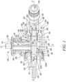
- FIG. 1 illustrates a pressure reducer assembly 100 according to an exemplary embodiment of the present invention.
- the pressure reducer assembly 100 is used for adjustably reducing a pressure of a fluid.
- the fluid is preferably a liquid, and more preferably water as water is the most frequently used fluid for various applications such as watering of lawns, cleaning, firefighting among others.
- fluid or liquid may interchangeably be used for water and vice versa.
- the pressure reducer assembly 100 may be mounted in an irrigation system 10.
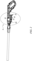
- FIGS. 2 and 3 illustrate the irrigation system 10 that includes a fluid outflow device 200 that comprises the pressure reducer assembly 100 and that is embodied as a handheld cleaning device 200.
- the fluid outflow device 200 is configured to guide an outflow of the fluid from the pressure reducer assembly 100.
- the fluid outflow device 200 may be used for providing fluid for various industrial and domestic applications such as, but not limited to, cleaning.
- the fluid outflow device 200 shown in FIGS. 2 and 3 is a handheld cleaning device.
- FIG. 2 illustrates a cross-sectional side view of the cleaning device that comprises the pressure reducer assembly 100.
- FIG. 3 illustrates a zoomed cross-sectional side view of an encircled portion of the cleaning device that comprises the pressure reducer assembly 100.
- the fluid outflow device 200 includes a housing 210 as illustrated in FIGS. 1 , 2 and 3 .
- the housing 210 includes an inlet port 213.
- the inlet port 213 may receive water for operation from a water source (not shown).
- the inlet port 213 may supply water received from the water source to the pressure reducer assembly 100.
- the housing 210 further includes the outlet port 215 which is according to the illustrated embodiment formed as a nipple 215.
- the outlet port 215 may receive water from the pressure reducer assembly 100 and may guide the water out of the pressure reducer assembly 100 for further applications.
- the outlet port 215 includes a sealing protrusion 218.
- the housing 210 includes an inside surface 216 and an outside surface 217.
- the inside surface 216 is disposed opposite to the outside surface 217.
- the inside surface 216 includes an axial end face 219 and a radial end face 220.
- the axial end face 219 axially supports a pressure reducer body 110 of the pressure reducer assembly 100.
- the axial end face 219 provides a seat for the pressure reducer body 110.
- the pressure reducer body 110 is form-fitted or friction fitted with the inside surface 216 of the housing 210.
- the pressure reducer body 110 is quickly and ergonomically mounted to the housing 210 because its outer diameter is adjusted to an inner diameter of the housing 210 of the fluid outflow device 200.
- the pressure reducer body 100 is mounted, preferably screw-less mounted, into the housing 210 of the fluid outflow device 200.
- the pressure reducer body 110 of the present disclosure is a cylindrical body having a central axis X-X' along a longitudinal or axial direction of the pressure reducer assembly 100.
- the pressure reducer body 110 includes an outer surface 112 and an inner surface 114.
- the outer surface 112 is disposed opposite to the inner surface 114.
- a sealing ring 221 radially seals the outer surface 112 of the pressure reducer body 110 and the inside surface 216 of the housing 210.
- the sealing ring 221 may prevent leakage of water received via the inlet port 213.
- the sealing ring 221 is positioned in a groove in the outer surface 112 of the pressure reducer body 110.
- the sealing ring 221 on its radially outer surface contacts the inside surface 216 of the housing 210.
- the sealing ring 221 is sandwiched between the outer surface 112 of the pressure reducer body 110 and the radial end face 220 of the housing 210.
- the sealing ring 221 is firmly pressed in a direction perpendicular to the direction of the central axis X-X' by the housing 210 and the pressure reducer body 110.
- the sealing ring 221 is radially pressed between the housing 210 and the pressure reducer body 110 for sealing.
- the sealing ring 221 may prevent leakage of water received from the water source towards the area of the fluid coupling between the pressure reducer body 110 and the housing 210 and then further to the external environment.
- the pressure reducer body 110 in the mounted state, is completely enclosed by the housing 110.
- the pressure reducer body 110 is annularly separated from the external environment by the housing 210 of the fluid outflow device 200.
- the pressure reducer body 110 defines at least a part of a pressure reducer chamber 120 along the central axis X-X'.
- the inner surface 114 of the pressure reducer body 110 defines an annular boundary wall for the pressure reducer chamber 120.
- the pressure reducer chamber 120 includes an inlet section 122 and an outlet section 124 fluidly coupled with the inlet section 122.
- the inlet section 122 is configured to allow an inflow of the fluid into the pressure reducer chamber 120.
- the outlet section 124 is configured to allow an outflow of the fluid from the pressure reducer chamber 120.
- the pressure reducer assembly 120 includes a valve 128.
- the valve 128 is disposed at the inlet section 122 of the pressure reducer chamber 120.
- the valve 128 is configured to selectively allow and disallow a flow of fluid (particularly water) through the pressure reducer assembly 100.
- the valve 128 selectively allows and disallows passage of water via the inlet section 122.
- the valve 128 selectively allows the passage of water to the outlet section 124 such as to support maintaining a constant output pressure of the pressure reducer assembly 100 and hence the irrigation system 10.
- the valve 128 may be coupled to the inlet section 122 by any suitable means known in the art. However, in an exemplary embodiment , the valve 128 is screwed to the inlet section 122.
- the screw coupling between the valve 128 and the inlet section 122 may be established by corresponding threads on the one hand on a body structure of the valve 128 and on the other hand on the pressure reducer body 110.
- the screw coupling may be established by screwing the valve 128 to an internal thread of the pressure reducer body 110 by simultaneously cutting a thread on the body structure of the valve 128.
- Both may allow a movement of the valve 128 relative to the inlet section 122 along the longitudinal direction or the direction of central axis X-X' of the pressure reducer assembly 100 for example for adjusting purposes.
- the screw coupling between the valve 128 and the inlet section 122 allows for movement of the valve 128 relative to the inlet section 122 along the direction of the central axis X-X'.
- the movement of the valve 128 along the longitudinal direction of the pressure reducer assembly 100 may also help in adjusting the constant output pressure generated by the pressure reducer assembly 100.
- the valve 128 further includes a seal 126.
- the seal 126 may be O-ring or any other type of seal generally available in the related art.
- the inlet section 122 may include a filter element (not shown) located upstream of the valve 128.
- the valve 128 may be located downstream of the filter element in the direction of water flow.
- the filter element may be operatively coupled to the inlet section 122 such that the filter element filters water received from the water source before it enters the pressure reducer chamber 120.
- the filter element prevents clogging of the inlet section 122 and thereby promotes smooth operations of the pressure reducer assembly 100 and the irrigation system 10.
- the pressure reducer assembly 100 further includes a biasing means piston rod 132.
- the piston rod 132 is a hollow rod allowing passage of water of which the pressure is to be reduced in the pressure reducer assembly 100.
- the piston rod 132 has a center Y along the central axis X-X'.
- the piston rod 132 connects the inlet section 122 with the outlet section 124.
- the piston rod 132 allows a fluid, particularly water, to flow from the inlet section 122 towards the outlet section 124.
- the piston rod 132 is located downstream of the valve 128.
- the seal 126 radially seals the piston rod 132.
- the piston rod 132 includes an inner surface 130 and an outer surface 131.
- the inner surface 130 is in touch with the water flowing through the piston rod 132 whereas the outer surface 131 faces the pressure reducer chamber 120 and/or the inside surface 216 of the housing 210.
- a spring element 134 is the biasing means of the piston rod 132.
- the spring element 134 is functionally coupled with the piston rod 132 and is configured to allow an axial movement of the piston rod 132 along the central axis X-X'.
- the spring element 134 may provide enough spring force to operate the piston rod 132.
- the spring element 134 may have length enough to generate strength to operate the piston rod 132.
- the spring element 134 may not have strength more than what is required to operate the piston rod 132 as the greater strength of the spring element 134 leads to greater installation space of the spring element 134 and thus an unnecessary increase in size of the pressure reducer assembly 100.
- the spring element 134 as illustrated in Fig. 1 , is a compression spring.
- piston rod 132 may be concentric with the pressure reducer body 110 or the pressure reducer chamber 120. It should be emphasized that the piston rod 132 may alternatively have any other orientation relative to the earlier defined central axis X-X' in accordance with the operational feasibility of the pressure reducer assembly 100.
- the piston rod 132 of the present disclosure is axially moveable with respect to the pressure reducer body 110.
- the piston rod 132 is configured to oscillate back and forth substantially within the pressure reducer chamber 120.
- the piston rod 132 oscillates to momentarily block the supply of water from the inlet section 122 towards the outlet section 124.
- the back-and-forth motion of the piston rod 132 is due to differential force experienced by the piston rod 132.
- the piston rod 132 is forced to exhibit a downward stroke i.e., towards the inlet section 122 when the pressure at the outlet section 124 is larger than a predefined/preset constant output pressure. In other words, when the pressure at the outlet section 124 is more than required for the application for which the pressure reducer assembly 100 is intended for use. Further, the piston rod 132 exhibits an upward stroke i.e., towards the outlet section 124 when the pressure at the outlet section 124 is smaller than a predefined/preset constant output pressure. In other words, when the pressure at the outlet section 124 is less than the pressure required for the application for which the pressure reducer assembly 100 is intended for use.
- water in the outlet section 124 is prevented from leaking back to the pressure reducer chamber 120 by a sealing element 136 operatively coupled with the piston rod 132.
- the sealing element 136 is configured to form a sealing a between the inside surface 216 of the fluid outflow device 200 and the outer surface 131 of the piston rod 132.
- the sealing element 136 disallows a backflow of water past the outlet section 124, thereby eliminating any possible leakage and improving the overall efficiency of the pressure reducer assembly 100 installed in the fluid outflow device 200.
- the sealing element 136 is a diaphragm 136.
- the sealing element 136 is now interchangeably written as the diaphragm 136.
- the diaphragm 136 communicates an excess water pressure at the outlet section 124 to the piston rod 132 for downward stroke of the piston rod 132.
- the diaphragm 136 allows the sealing between the inside surface 216 of the fluid outflow device 200 and the outer surface 131 of the piston rod 132.
- the multiple usage or application of the diaphragm 136 means no separate sealing elements such as O-rings are required for the sealing.
- the diaphragm 136 provides an axial sealing between the outer surface 131 of the piston rod 132 and the radial sealing protrusion 218 of the outlet port 215.
- a radial outer part of the diaphragm 136 is axially sealed by clamping it between an axial outlet end face 116 of the pressure reducer body 110 and the radial sealing protrusion 218 of the outlet port 215. Thereby, the diaphragm 136 is securely held in place.
- an outer periphery of the diaphragm 136 is pressed or sandwiched by the pressure reducer body 110 and the nipple 215.
- an inner periphery of the diaphragm 136 is supported or sandwiched by a plurality of annular protrusions 132A, 132B formed on the outer surface 131 of the piston rod 132.
- the diaphragm 136 is well supported and stable against pressure differences in the pressure reducer chamber 120.
- the diaphragm 136 is prevented from any slippage or misplacement in the pressure reducer assembly 100 by virtue of the piston rod 132, the pressure reducer body 110, the housing 210 and the nipple 215.
- the force experienced by the piston rod 132 is caused by the spring element 134 and the sealing element 136 operatively coupled with the piston rod 132 in the pressure reducer chamber 120.
- the direction of motion of the piston rod 132 at any particular time instant is governed by the direction of net force generated upon the piston rod 132 by the spring force caused by the spring element 134 and the fluid pressure force on the sealing element 136.
- the piston rod 132 moves in upstream direction (as shown in FIG. 1 ) when the net force is in upstream direction due to higher amount of force generated by the fluid acting on the surface of the sealing element 136 relative to the spring force, particularly the restoring force, generated by the spring element 134.
- the upstream direction may be defined as the direction which is opposite to the direction of flow of water.
- the constant output pressure generated by the pressure reducer assembly 100 may be adjusted by varying an initial distance or an initial gap between the piston rod 132, the valve 128 and the seal 126 during the manufacturing of the pressure reducer assembly 100 or just before mounting the pressure reducer assembly 100 to the housing 210 of the fluid outflow device 200.
- the constant output pressure may be pre-determined and preset during the manufacturing of the pressure reducer assembly 100 according to the application requirements of the fluid outflow device 200 to which the pressure reducer assembly 100 is mounted.
- the pressure reducer assembly 100 is configured to generate a constant output pressure of at least 1.5 bar, particularly of at least 3 bar, more particularly of substantially 4 bar. Some applications may demand the constant output pressure of 4 bar while other applications such as drip heads and spray nozzles used for gardening operations may demand the constant output pressure of 1.5 bar.
- the stiffness of the used spring element 134 is chosen dependent on the desired constant output pressure. Particularly, using a spring element 134 having a hard spring stiffness may result in a constant high output pressure, e.g., 4 bar. On the other hand, using a spring element 134 having a soft spring stiffness may result in a constant low output pressure, e.g., 1.5 bar. By increasing the initial distance or the initial gap between the piston rod 132, the valve 128 and the seal 126 a constant output pressure of 4 bar may be generated, while by comparatively reducing it, a constant output pressure of 1.5 bar may be generated.
- the pressure reducer assembly 100 includes the pressure reducer body 110 which further includes the pressure reducer chamber 120.
- the pressure reducer chamber 120 requires a pressure compensation feature to ensure unrestricted mobility of the piston rod 132.
- the pressure compensation feature is provided by an opening 211 (as shown in FIG. 5 ) provided with the housing 210.
- the opening 211 allows release of air pressure generated in the pressure reducer chamber 120 when the piston rod 132 moves in an upstream direction seen in a flow direction of the fluid through the pressure reducer assembly 100.
- the opening 211 allows air to flow out of the pressure reducer chamber 120 when the piston rod 132 moves in the upstream direction (as shown in FIG. 1 ).
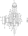
- the opening 211 allows suction of surrounding air (external to the pressure reducer assembly 100) when the piston rod 132 moves in a downstream direction seen in a flow direction of the fluid through the pressure reducer assembly 100 (as shown in FIG. 4 ).
- the sealing element 136 may prevent ingress of air in the outlet section 124, thereby preventing mixing of air drawn-in from the opening 211, with water.
- the pressure reducer assembly 100 in addition to the pressure reduction of the water flowing from the inlet section 122 to the outlet section 124 is advantageously capable of functioning as a shut-off valve.
- the piston rod 132 of the pressure reducer assembly 100 includes an interaction protrusion 133.
- the pressure reducer assembly 100 further includes an adjusting device 140.
- the adjusting device 140 is positioned eccentrically to the central axis X-X'.
- the eccentric positioning of the adjusting device 140 relative to the central axis X-X' may allow proper functioning of the components such as the piston rod 132 and others in the pressure reducer chamber 120 to accurately reduce the pressure of the fluid flowing through the pressure reducer chamber 120 while still providing an add-on functionality of the shut-off valve in addition to the conventional pressure reduction function.
- FIGS. 1 and 4 illustrates the adjusting device 140 eccentrically positioned to the central axis X-X' along an axis Z-Z' which may be substantially perpendicular to the central axis X-X'.
- the adjusting device 140 includes an actuating part 141 and an adjusting part 142.
- the actuating part 141 and the adjusting part 142 are functionally coupled to each other such that any movement in the actuating part 141 translates into the movement in the adjusting part 142.
- the adjusting part 142 is configured to functionally interact with the interaction protrusion 133 such that a maximum axial movement of the piston rod 132 is adjustable by actuating the actuating part 141, particularly by manually actuating the actuating part 141. Further, an amount of an actuation of the actuating part 141 is directly linked to an amount of a maximum axial movement of the piston rod 132. In other words, the maximum axial movement of the piston rod 132 may be directly proportional to the amount of actuation of the actuating part 141. For example, complete actuation of the actuating part 141 may lead to maximum axial movement of the piston rod 132 and no actuation of the actuating part 141 may lead to no axial movement of the piston rod 132.
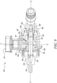
- FIG. 4 shows the piston rod 132 with maximum axial movement whereas FIG. 1 shows the piston rod 132 with no axial movement.
- the position of the maximum axial movement of the piston rod 132 is denoted by “ P1 ".
- the position of the piston rod 132 with no axial movement is denoted by "P2”.
- the actuating part 141 is a rotary knob 141.
- the rotary knob 141 may be ergonomically suitable for actuation of the adjusting device 140. Further, the rotary knob 141 may be easily grabbed by the operator. Further, the rotary knob 141 is simple in construction and simple to actuate even by the operator not skilled in the art.
- the interaction protrusion 133 is formed as a radially extending protrusion extending from the outer surface 131 of the piston rod 132.
- the interaction protrusion 133 extends in particular about at least half of a circumference of the piston rod 132, further in particular about substantially an entire circumference of the piston rod 132. If a portion of the interaction protrusion 133 wears out or damages during operation of the pressure reducer assembly 100, the piston rod 132 may simply be rotated to functionally recruit other portions of the interaction protrusion 133 for interaction with the adjusting part 142 which were earlier not in any sort of interaction with the adjusting part. This may potentially avert recurrent maintenance and overhauling of the pressure reducer assembly 100.
- the adjusting part 142 includes a scenery geometry portion 144.
- the scenery geometry portion 144 is configured such that, when the scenery geometry portion 144 is functionally interacting with the interaction protrusion 133, the scenery geometry portion 144 is in contact with the interaction protrusion 133 such that an axial force is introducible from the scenery geometry portion 144 on the interaction protrusion 133, and the maximum axial movement of the piston rod 132 is adjustable.
- the scenery geometry portion 144 may be a portion of the adjusting part 142 that may actually functionally interact with the interaction protrusion 133 for axial force transfer between the adjusting device 140 and the piston rod 132.
- the scenery geometry portion 144 may functionally interact with the interaction protrusion 133 upon actuation of the actuating part 141 of the adjusting device 140.
- the piston rod 132 moves to position "P2".
- the scenery geometry portion 144 is located below the actuating part 141 of the adjusting device 140 such that the scenery geometry portion 144 and the actuating part 141 of the adjusting device 140 may be functionally coupled with each other. In other words, any movement in the actuating part 141 may be translated to the movement in the scenery geometry portion 144.
- the adjusting part 142 further includes a stop portion 148.
- the stop portion 148 is configured such that, when the stop portion 148 is functionally interacting with the interaction protrusion 133, the stop portion 148 is in contact with the interaction protrusion 133 such that the axial force is introducible from the stop portion 148 on the interaction protrusion 133, and the maximum axial movement of the piston rod 132 is substantially inhibited.
- the adjusting part 142 comprises at least two, preferably four (as illustrated in FIG. 1 ), bearing ribs 150.
- Each of the bearing ribs 150 extend along a main extension of the adjusting part 142 and parallel to the axis Z-Z'.
- the four bearing ribs 150 are arranged with a spacing of substantially 90° between two adjacent bearing ribs 150. Hence, the four bearing ribs 150 are evenly spaced from each other.
- the bearing ribs 150 are configured and are used for concentric bearing of the adjusting device 140 in the opening 211.
- the adjusting part 142 further includes a guide portion 146.
- the guide portion 146 is configured such that, when the guide portion 146 is functionally interacting with the interaction protrusion 133, a contact between the adjusting part 142 and the interaction protrusion 133 is disengaged, and the piston rod 132 is substantially contact-free axially movable relative to the guide portion 146.
- the guide portion 146 may comprise two sub guide portions 146 arranged uniformly spaced by 180° from each other on the adjusting device 140 to allow a free axial movement of the piston rod 132.
- the two sub guide portions 146 may be cubical or cuboidal in shape.
- the adjusting device 140 comprises the adjusting part 142 and the actuating part 143.
- the adjusting part 142 comprises the guide portion 146, the scenery geometry portion 144 and the stop portion 146, wherein the scenery geometry portion 144 extends between the stop portion 148 and the guide portion 146.
- the guide portion 146, the scenery geometry portion 144, and the stop portion 148 may be arranged in such a manner that they alternatively functionally interact with the interaction protrusion 133 of the piston rod 132.
- the piston rod 132 When the guide portion 146 functionally interacts with the interaction protrusion 133 of the piston rod 132, then the piston rod 132 does not experience any axial force from the adjusting device 140 and hence the maximum axial movement of the piston rod 132 is completely free until its end defined by constraints of the construction of the pressure reducer assembly 100. However, when the scenery geometry portion 144 functionally interacts with the interaction protrusion 133 of the piston rod 132, then the piston rod 132 experiences the axial force such as to adjust the maximum axial movement of the piston rod 132 to a desired value in-between a zero maximum axial movement and a completely free maximum axial movement until its end defined by constraints of the construction of the pressure reducer assembly 100.
- the scenery geometry portion 144 lags behind the guide portion 146 in the upstream direction of the fluid flow when the guide portion 146 functionally interacts with the pressure reducer body 110 (as shown in FIG. 4 ).
- the piston rod 132 does not encounter any axial force that may inhibit the free axial movement of the piston rod 132.
- the flow of fluid from the inlet section 122 of the pressure reducer chamber 120 to the outlet section 124 of the pressure reducer chamber 120 is allowed when the guide portion 146 functionally interacts with the interaction protrusion 133. Further, a flow of fluid from the inlet section 122 of the pressure reducer chamber 120 to the outlet section 124 of the pressure reducer chamber 120 is allowed when the scenery geometry portion 144 functionally interacts with the interaction protrusion 133. In contrast, as illustrated in FIG. 1 , a flow of fluid from the inlet section 122 of the pressure reducer chamber 120 to the outlet section 124 of the pressure reducer chamber 120 is disallowed respectively inhibited when the stop portion 148 functionally interacts with the interaction protrusion 133. Resultantly, the pressure reducer assembly 100 of the present invention provides the functionality of the conventional pressure reducer and the conventional shut-off valve.
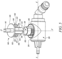
- FIG. 5 illustrates a side perspective view of the housing 210 and the adjusting device 140 in a disassembled state.
- the housing 210 includes the opening 211.
- the opening 211 is a cylindrical opening.
- the adjusting device 140 is fixedly and movably mounted to the housing 210.
- the adjusting device 140 is rotatably mounted to the housing 210.
- the adjusting part 142 of the adjusting device 140 that includes the scenery geometry portion 144, the guide portion 146 and the stop portion 148 is completely enclosed by the opening 211 in an assembled state.
- the adjusting part 142 is not visible to the operator when the adjusting device 140 is mounted to the housing 210.
- the opening 211 includes two first ribs 212 and the adjusting device 140 includes two attachment parts 149, wherein the attachment parts 149 are configured to mount the adjusting device 140 to the opening 211, and wherein each of the two attachment parts 149 comprises an end stop 152.
- the first rib 212 and the end stop 152 are configured to interact with each other to limit a rotational movement of the adjusting device 140 relative to the opening 211.
- the two first ribs 212 are spaced apart from each other by 180°.
- the two attachment parts 149 are positioned opposite to each other. In other words, the two attachment parts 149 are arranged on two different sides of the axis Z-Z'.
- the at least one first rib 212 radially project from the outer surface of the opening 211. Further, the at least one first rib 212 extend along the length of the opening 211 along a direction parallel to the axis Z-Z'.
- the at least one attachment part 149 and the at least one stop end 152 extends in a downward direction from the outer periphery 145 of the adjusting device 140.
- the at least one attachment part 149 and the at least one end stop 152 extend along the axis Z-Z'.
- the at least one attachment part 149 is an hook-shaped part with a seating protrusion 147 at the lower end which is the end spaced apart from the outer periphery 145, and the respective end stop 152 at each of two circular end faces.
- the seating protrusion 147 geometrically interact with an outer housing of the fluid outflow device 200 such that the adjusting device is movably fixed to the outer housing of the fluid outflow device 200.
- each of the two attachment parts 149 rotates between two first ribs 212.
- the interaction between the two first ribs 212 and the end stops 152 allow a 90° turn of the rotary knob 141 which corresponds to a movement between a completely open position and a completely closed position of the pressure reducer assembly 100.
- the opening 211 comprises an engaging section 214 which extends in the circumferential direction between the two attachment parts 149.
- the engaging section 214 comprises a plurality of protrusions and indentions which are formed adjacent to each other.
- the plurality of protrusions and indentations are formed in a substantial zigzag shape and each extend parallel to the axis Z-Z' .
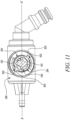
- the engaging section 214 is configured to interact with a latch nose 153 (shown in FIGS. 8 and 11 ) to ensure an angular position of the adjusting device 140 relative to the opening 211.
- ensuring the angular position of the adjusting device 140 relative to the opening 211 and therefore the housing 210 may be performed by using an O-ring instead of the engaging section 214 and the latch nose 153.
- the fluid outflow device 200 shown in FIGS. 6 and 7 is a shower.
- the shower 200 mounts the pressure reducer assembly 100.
- the pressure reducer assembly 100 is mounted in the shower of the irrigation system 10 .
- the pressure reducer assembly 100 mounted in the shower and shown in FIGS. 6 and 7 also includes a similar pressure reducer chamber 120 and the associated components as with the pressure reducer assembly 100 mounted in the cleaning device as shown in FIGS. 1 and 4 along the central axis X-X'.
- the pressure reducer assembly 100 illustrated in FIGS. 6 and 7 includes the radial lip 136 as the sealing element 136.
- the shower includes a nipple 224 that functions as the inlet port 213.
- the nipple 224 includes an O-ring 223 for fluid tight coupling with a water connection such as a hose (not shown in FIGS. 6 and 7 ).
- the nipple 224 is threadedly engaged to the inside surface 216 of the shower respectively the fluid outflow device 200.
- the pressure reducer assembly 100 as illustrated in FIGS. 6 and 7 in addition to the pressure reduction of the water is further advantageously capable of functioning as a shut-off valve.
- the piston rod 132 of the pressure reducer assembly 100 includes the interaction protrusion 133.
- the pressure reducer assembly 100 further includes the adjusting device 140.
- the adjusting device 140 is positioned eccentrically to the central axis X-X'. The eccentric positioning of the adjusting device 140 relative to the central axis X-X' may allow proper functioning of the components such as the piston rod 132 and others in the pressure reducer chamber 120 to accurately reduce the pressure of the fluid flowing through the pressure reducer assembly 100 while still providing an add-on functionality of the shut-off valve in addition to the conventional pressure reduction function.
- the adjusting device 140 includes the actuating part 143 and the adjusting part 142.
- the actuating part 143 and the adjusting part 142 are functionally coupled to each other such that any movement in the actuating part 143 translates into a movement in the adjusting part 142.
- the adjusting part 142 is configured to functionally interact with the interaction protrusion 133 such that the maximum axial movement of the piston rod 132 is adjustable by actuating the actuating part 143, particularly by manually actuating the actuating part 143. Further, the amount of the actuation of the actuating part 143 is directly linked to the amount of the maximum axial movement of the piston rod 132.
- the maximum axial movement of the piston rod 132 may be directly proportional to the amount of actuation of the actuating part 143.
- complete actuation of the actuating part 143 particularly by a90° turn, may lead to completely free axial movement of the piston rod 132 and no actuation of the actuating part 143 may lead to an inhibited axial movement of the piston rod 132.
- FIG. 6 shows the piston rod 132 with maximum axial movement limited by an interaction of the scenery geometry portion 144 with the interaction protrusion 133. This is denoted as position “P3" in the following.
- FIG. 7 shows the piston rod 132 in position "P2", wherein the interaction protrusion 132 functionally interacts with the stop portion 148 such that no axial movement of the piston rod 132 is possible. In other words, such that the axial movement of the piston rod 132 is inhibited.
- a flow of water through the pressure reducer chamber 120 is substantially entirely inhibited.
- a flow of water through the pressure reducer chamber 120 is allowed.
- the actuating part 143 is a lever 143.
- the lever 143 may be ergonomically suitable for actuation of the adjusting device 142. Further, the lever 143 may be easily grabbed by the operator. Further, the lever 143 is simple in construction and simple to actuate even by the operator not skilled in the art.
- the interaction protrusion 133 is formed as a stop rib 133 axially extending on the outer surface 131 of the piston rod 132.
- the adjusting device 140 includes a wedge-shaped scenery geometry portion 144 coupled with/formed on the lever 143.
- the scenery geometry portion 144 may functionally interact with the interaction protrusion 133 such that when the stop rib 133 functionally interacts with the scenery geometry portion 144 of the lever 143, the maximum axial movement of the piston rod 132 is individually adjustable.
- the scenery geometry portion 144 is part of the adjusting part 142 of the adjusting device 140.
- the adjusting part 142 further includes the stop portion 148 as well as the guide portion 146. As illustrated in FIGS. 6 and 7 , the scenery geometry portion 144 extends between the stop portion 148 and the guide portion 146.
- the stop portion 148 is configured such that, when the stop portion 148 is functionally interacting with the interaction protrusion 133, the stop portion 148 is in contact with the interaction protrusion 133 such that the axial force is introducible from the stop portion 148 on the interaction protrusion 133, and the maximum axial movement of the piston rod 132 is substantially inhibited.
- the adjusting part 142 further includes the guide portion 146.
- the guide portion 146 is configured such that, when the guide portion 146 is functionally interacting with the interaction protrusion 133, contact between the adjusting part 142 and the interaction protrusion 133 is disengaged, and the piston rod 132 is substantially contact-free axially movable relative to the guide portion 146.
- the pressure reducer assembly 100 of the present invention provides at the same time in one assembly the functionality of a pressure reducer and a shut-off valve.
- the operator of the fluid application assembly 100 presses the lever 143 or rotates the rotary knob 141 from a switched off position of the pressure reducer assembly 100, also referred to as position "P2", to a plurality of switched-on positions of the pressure reducer assembly 100, also referred to as position "P1" and position “P3".
- the switched-off position "P2” the pressure reduction and the water flow features are stopped.
- the plurality of switched-on positions, particularly position "P1" and position "P3” the pressure reduction feature is on and a water flow through the pressure reducer chamber 120 is also allowed.
- the spring element 134 may initially move from a compressed state, as shown in FIG. 1 and FIG. 7 , to a more expanded state as shown in FIG. 4 and FIG.
- the spring element 134 may expand and compress due to the already discussed differential pressure in the pressure reducer chamber 120 and the water flow is momentarily decreased and increased from time to time. Furthermore, when the operator actuates the actuating part 141, 143 such that the scenery geometry portion 144 and the interaction protrusion 133 functionally interact with each other, the spring element 134 may not extend to its maximum extension.
- FIG. 8 illustrates a perspective view of a adjusting device 140.
- the adjusting device 140 comprises four bearing ribs 150 of which three are shown in FIG. 8 , two guide portions 146 spaced apart from each other by 180°, two stop portions 148 spaced apart from each other by 180° and spaced apart from the two guide portions 146 by 90°, and four scenery geometry portions 144 each extending between a guide portion 146 and an adjacent stop portion 148.
- Two of the four bearing ribs 150 are each formed in extension of a respective one of the two guide portions 146 and the other two bearing ribs 150 are each formed in extension of a respective one of the two stop portions 148.
- the stop portion 148 comprises a stop width 158 which is configured to ensure that when the stop portion 148 is functionally interacting with the interaction protrusion 133, an axial movement of the piston rod 132 is inhibited.
- the guide portion 146 comprises a guide width 156 which is configured to ensure that, when the guide portion 146 is functionally interacting with the interaction protrusion 133, the piston rod 132 may completely freely axially move with respect to the adjusting device 140. As shown in FIG. 8 , the guide width 156 is smaller than the stop width 158.
- the guide width 146 corresponds to the length between the axis Z-Z' and an outer surface of the guide portion 146.
- the stop width 158 corresponds to the length between the axis Z-Z' and the stop portion 148.
- the adjusting device 140 comprises two latch noses 151.
- Each of the two latch noses 151 is formed on an inner surface of the respective one of the two attachment parts 149.
- the latch nose 151 is configured to engage with one of the indentions of the engaging section 214 (shown in FIG. 5 ) for fixing an angular position of the adjusting device 140 relative to the housing 210.
- FIG. 9 illustrates a further cross-sectional side view of a pressure reducer assembly 100 during mounting to a housing 210, in accordance with an exemplary embodiment of the present enclosure.
- the piston rod 132 is inserted in a direction of fluid flow, hence towards the outlet section 124 of the pressure reducer chamber 120 until an axial end 135 of the piston rod 132 abuts against an axial end stop structure 137.
- the axial end stop structure 137 is formed and configured to determine an axial position of the piston rod 132.
- the adjusting device 140 may be inserted into the opening 211, wherein the interaction protrusion 133 is in an axial position such that the guide portion 146 may pass the interaction protrusion 133 without interaction with the interaction protrusion 133 (shown in FIG. 9 by the dashed line) during a movement in a direction parallel to the axis Z-Z' (shown in FIG. 9 by the downward pointing arrow).
- the stop portion 148 functionally interacts with the interaction protrusion 133, the axial end 135 of the piston rod 132 is not in contact with the axial end stop structure 137.
- FIG. 10 illustrates a side view of a pressure reducer assembly 100 mounted to a housing 210 in a position in which the guide potion 146 functionally interacts with the interaction protrusion 133 and therefore, the piston rod 132 may freely axially move.
- FIG. 11 illustrates the pressure reducer assembly 100 mounted to the housing 210 of FIG. 10 in a cross-section along A-A.
- Each of the two first ribs 212 is in contact with a respective one of the two end stops 152. Thereby, a further rotational movement in the circumferential direction of the adjusting device 140 is inhibited.
- the two latch noses 153 each engage with a respective indention of one of the engaging sections 214. Thereby, the angular position of the adjusting device 140 relative to the housing 210 is defined and is kept also during using the fluid outflow device 200.
- the pressure reducer assembly 100 has a cost-efficient design, which is at the same time less error-prone due to less complex parts. Further, there is provision for quantity control via the rotary knob 141 or lever 143. Further, the pressure reducer assembly 100 has versatile applications for example in showers and cleaning devices.
- the present disclosure provides an improved pressure reducer assembly 100 that may be cost-effective, reliable, and simple in design.
- the pressure reducer assembly 100 includes the adjusting device 140 that may functionally interact with the piston rod 132 to advantageously adjust the maximum axial movement of the piston rod 132.
- the pressure reducer assembly 100 may at the same time reduce the pressure of the inlet fluid as well as function as a shut-off valve.
- the adjusting device 140 based on its rotation or linear movement may either allow or disallow the movement of the fluid through the pressure reducer assembly 100.
Landscapes
- Engineering & Computer Science (AREA)
- Physics & Mathematics (AREA)
- General Engineering & Computer Science (AREA)
- Fluid Mechanics (AREA)
- Mechanical Engineering (AREA)
- General Physics & Mathematics (AREA)
- Automation & Control Theory (AREA)
- Safety Valves (AREA)
- Control Of Fluid Pressure (AREA)
Claims (15)
- Ensemble détendeur (100) permettant de réduire de manière réglable une pression d'un fluide, de préférence un liquide, plus préférablement de l'eau, comprenant :un corps de détendeur (110) définissant au moins une partie d'une chambre de détendeur (120) le long d'un axe central (X-X'), dans lequel la chambre de détendeur (120) comprend une section d'entrée (122) et une section de sortie (124) accouplée fluidiquement à la section d'entrée (122), dans lequel la section d'entrée (122) est conçue pour permettre un écoulement entrant du fluide dans la chambre de détendeur (120), etdans lequel la section de sortie (124) est conçue pour permettre un écoulement sortant du fluide de la chambre de détendeur (120),une tige de piston (132) à moyen de sollicitation ayant un centre (Y) le long de l'axe central (X-X'), reliant la section d'entrée (122) à la section de sortie (124), et pouvant être déplacé axialement par rapport au corps de détendeur (110),caractérisé en ce que :la tige de piston (132) comprend une saillie d'interaction (133),l'ensemble détendeur (100) comprend en outre un dispositif de réglage (140) comprenant une pièce d'actionnement (141, 143) et une pièce de réglage (142),dans lequel la pièce de réglage (142) est conçue pour interagir de manière fonctionnelle avec la saillie d'interaction (133) de telle sorte qu'un mouvement axial maximal de la tige de piston (132) est réglable en actionnant la pièce d'actionnement (141), en particulier en actionnant manuellement la pièce d'actionnement (141).
- Ensemble détendeur (100) selon la revendication 1,
dans lequel une quantité d'un actionnement de la pièce d'actionnement (141) est directement liée à une quantité d'un mouvement axial maximal de la tige de piston (132). - Ensemble détendeur (100) selon la revendication 1 ou 2,dans lequel la pièce de réglage (142) comprend une partie géométrique de décor (144),dans lequel la partie géométrique de décor (144) est conçue de telle sorte que, lorsque la partie géométrique de décor (144) est en interaction fonctionnelle avec la saillie d'interaction (133), la partie géométrique de décor (144) est en contact avec la saillie d'interaction (133) de telle sorte qu'une force axiale peut être introduite à partir de la partie géométrique de décor (144) sur la saillie d'interaction (133), et de telle sorte que le mouvement axial maximal de la tige de piston (132) est réglable.
- Ensemble détendeur (100) selon l'une quelconque des revendications 1 à 3,dans lequel la pièce de réglage (142) comprend en outre une partie de butée (148),dans lequel la partie de butée (148) est conçue de telle sorte que, lorsque la partie de butée (148) est en interaction fonctionnelle avec la saillie d'interaction (133), la partie de butée (148) est en contact avec la saillie d'interaction (133) de telle sorte qu'une force axiale peut être introduite par la partie de butée (148) sur la saillie d'interaction (133), et de telle sorte que le mouvement axial maximal de la tige de piston (132) est sensiblement inhibé.
- Ensemble détendeur (100) selon l'une quelconque des revendications 1 à 4,dans lequel la pièce de réglage (142) comprend en outre une partie de guidage (146),dans lequel la partie de guidage (146) est conçue de telle sorte que, lorsque la partie de guidage (146) est en interaction fonctionnelle avec la saillie d'interaction (133), un contact entre la pièce de réglage (142) et la saillie d'interaction (133) est désolidarisé, et la tige de piston (132) est déplacée axialement sensiblement sans contact par rapport à la partie de guidage (146).
- Ensemble détendeur (100) selon l'une quelconque des revendications 1 à 5,
dans lequel le dispositif de réglage (140) est positionné de manière excentrique par rapport à l'axe central (X-X'). - Ensemble détendeur (100) selon l'une quelconque des revendications 1 à 6,dans lequel la pièce d'actionnement (141, 143) est un bouton rotatif (141),dans lequel la saillie d'interaction (133) est formée comme une saillie s'étendant radialement à partir d'une surface extérieure (131) de la tige de piston (132), en particulier sur au moins la moitié d'une circonférence de la tige de piston (132), en outre en particulier sur une circonférence sensiblement entière de la tige de piston (132).
- Ensemble détendeur (100) selon l'une quelconque des revendications 5 à 7,
dans lequel la pièce de réglage (142) est formée de telle sorte que la partie géométrique de décor (144) s'étend entre la partie de butée (148) et la partie de guidage (146). - Ensemble détendeur (100) selon l'une quelconque des revendications 1 à 6,dans lequel la pièce d'actionnement (141, 143) est un levier (143), etdans lequel la saillie d'interaction (133) est formée comme une nervure de butée s'étendant axialement sur une surface extérieure (152) de la tige de piston (132).
- Ensemble détendeur (100) selon l'une quelconque des revendications 1 à 9,dans lequel le moyen de sollicitation est un élément ressort (134),dans lequel l'élément ressort (134) est accouplé de manière fonctionnelle à la tige de piston (132) et est conçu pour permettre un mouvement axial de la tige de piston (132) le long de l'axe central (X-X').
- Ensemble détendeur (100) selon l'une quelconque des revendications 1 à 10, comprenant en outreun élément d'étanchéité (136) accouplé de manière opérationnelle à la tige de piston (132),dans lequel l'élément d'étanchéité (136) est conçu pour former un joint d'étanchéité entre une surface intérieure (216) d'un dispositif d'écoulement sortant de fluide (200) et une surface extérieure (131) de la tige de piston (132), etdans lequel en particulier l'élément d'étanchéité (136) est un diaphragme (136).
- Ensemble détendeur (100) selon l'une quelconque des revendications 1 à 11,
dans lequel l'ensemble détendeur (100) est conçu pour générer une pression de sortie constante d'au moins 1 bar, en particulier d'au moins 3 bar, plus particulièrement de sensiblement 4 bar. - Ensemble détendeur (100) selon l'une quelconque des revendications 1 à 12, comprenant en outreune soupape (128) au niveau de la section d'entrée (122) de la chambre de détendeur (120), etdans lequel la soupape (128) est conçue pour permettre et empêcher sélectivement un écoulement de fluide à travers l'ensemble détendeur (100).
- Système d'irrigation (10) comprenantun ensemble détendeur (100) selon l'une quelconque des revendications 1 à 13, etun dispositif d'écoulement sortant de fluide (200) conçu pour guider un écoulement sortant du fluide à partir de l'ensemble détendeur (100),dans lequel le dispositif d'écoulement sortant de fluide (200) est en particulier une seringue, une douche, un dispositif de brossage, un dispositif de nettoyage, ou un élément d'irrigation au goutte-à-goutte,dans lequel l'ensemble détendeur (100) est monté sur le dispositif d'écoulement sortant de fluide (200), etdans lequel le dispositif d'écoulement sortant de fluide (200) comprend un boîtier (210) doté d'une ouverture (211),dans lequel le dispositif de réglage (140) est monté de manière fixe et mobile sur le boîtier (210),dans lequel l'ouverture (211) comprend au moins une première nervure (212), etdans lequel le dispositif de réglage (140) comprend au moins une pièce de fixation (149) conçue pour monter le dispositif de réglage (140) sur l'ouverture (211), et comprenant une butée d'extrémité (152),dans lequel la première nervure (212) et la butée d'extrémité (152) sont conçues pour interagir l'une avec l'autre afin de limiter un mouvement du dispositif de réglage (140) par rapport à l'ouverture (211).
- Système d'irrigation (10) selon la revendication 14,
dans lequel l'ouverture (211) permet une compensation de pression de l'ensemble détendeur (100).
Priority Applications (6)
| Application Number | Priority Date | Filing Date | Title |
|---|---|---|---|
| PL23159179.3T PL4425295T3 (pl) | 2023-02-28 | 2023-02-28 | Zespół reduktora ciśnienia |
| EP23159179.3A EP4425295B1 (fr) | 2023-02-28 | 2023-02-28 | Ensemble réducteur de pression |
| FIEP23159179.3T FI4425295T3 (fi) | 2023-02-28 | 2023-02-28 | Paineenalenninkokoonpano |
| CN202410216307.9A CN118564702A (zh) | 2023-02-28 | 2024-02-27 | 减压器组件 |
| US18/588,780 US12572163B2 (en) | 2023-02-28 | 2024-02-27 | Pressure reducer assembly |
| TW113106922A TW202449547A (zh) | 2023-02-28 | 2024-02-27 | 減壓器組件及包括其的灌溉系統 |
Applications Claiming Priority (1)
| Application Number | Priority Date | Filing Date | Title |
|---|---|---|---|
| EP23159179.3A EP4425295B1 (fr) | 2023-02-28 | 2023-02-28 | Ensemble réducteur de pression |
Publications (2)
| Publication Number | Publication Date |
|---|---|
| EP4425295A1 EP4425295A1 (fr) | 2024-09-04 |
| EP4425295B1 true EP4425295B1 (fr) | 2025-01-29 |
Family
ID=85410208
Family Applications (1)
| Application Number | Title | Priority Date | Filing Date |
|---|---|---|---|
| EP23159179.3A Active EP4425295B1 (fr) | 2023-02-28 | 2023-02-28 | Ensemble réducteur de pression |
Country Status (6)
| Country | Link |
|---|---|
| US (1) | US12572163B2 (fr) |
| EP (1) | EP4425295B1 (fr) |
| CN (1) | CN118564702A (fr) |
| FI (1) | FI4425295T3 (fr) |
| PL (1) | PL4425295T3 (fr) |
| TW (1) | TW202449547A (fr) |
Family Cites Families (8)
| Publication number | Priority date | Publication date | Assignee | Title |
|---|---|---|---|---|
| US892450A (en) * | 1908-03-02 | 1908-07-07 | Thomas Robinson | Pressure-reducing valve. |
| US4516600A (en) * | 1982-05-14 | 1985-05-14 | Sturman Oded E | Pressure regulating valves |
| US6202682B1 (en) | 1999-01-04 | 2001-03-20 | Dwight N. Johnson | Pressure regulator with selector control |
| EP1043657A1 (fr) | 1999-04-06 | 2000-10-11 | Siemens Aktiengesellschaft | Objet de logiciel, système et méthode pour un programme d'automatisation avec des règles de fonction avec utilisation multiple pour différents outils de programmation |
| US6932108B2 (en) * | 2003-04-17 | 2005-08-23 | Hans Sasserath & Co Kg | Pressure reducer |
| US7007714B2 (en) * | 2003-12-05 | 2006-03-07 | Hose Shop, Ltd. | High pressure traverse flow adjustable gas regulator |
| US7261119B2 (en) * | 2004-02-04 | 2007-08-28 | S.H. Leggitt Company | Pressure regulator with improved outlet pressure control |
| US8567433B2 (en) * | 2011-03-11 | 2013-10-29 | Nelson Irrigation Corporation | Pressure regulator with manual shut-off valve |
-
2023
- 2023-02-28 EP EP23159179.3A patent/EP4425295B1/fr active Active
- 2023-02-28 PL PL23159179.3T patent/PL4425295T3/pl unknown
- 2023-02-28 FI FIEP23159179.3T patent/FI4425295T3/fi active
-
2024
- 2024-02-27 US US18/588,780 patent/US12572163B2/en active Active
- 2024-02-27 CN CN202410216307.9A patent/CN118564702A/zh active Pending
- 2024-02-27 TW TW113106922A patent/TW202449547A/zh unknown
Also Published As
| Publication number | Publication date |
|---|---|
| TW202449547A (zh) | 2024-12-16 |
| EP4425295A1 (fr) | 2024-09-04 |
| PL4425295T3 (pl) | 2025-04-07 |
| CN118564702A (zh) | 2024-08-30 |
| FI4425295T3 (fi) | 2025-03-03 |
| US12572163B2 (en) | 2026-03-10 |
| US20240288888A1 (en) | 2024-08-29 |
Similar Documents
| Publication | Publication Date | Title |
|---|---|---|
| US7871020B2 (en) | Faucet spray head with volume control | |
| US5634491A (en) | Flow control valve assembly | |
| US11822354B1 (en) | Pressure reducer | |
| US20060108383A1 (en) | Device for dispensing a heated liquid having a flexible hydraulic seal | |
| EP4320496B1 (fr) | Réducteur de pression | |
| KR20220113917A (ko) | 휴대형 유량 제어 릴리즈 밸브 | |
| EP4425295B1 (fr) | Ensemble réducteur de pression | |
| KR20110096211A (ko) | 분무기용 스프레이건 | |
| KR101179375B1 (ko) | 감압밸브 | |
| TWI885380B (zh) | 減壓器組件 | |
| WO2010122119A1 (fr) | Dispositif d'alimentation en eau à élément de distribution d'eau amélioré, et élément de distribution d'eau amélioré pour ledit dispositif | |
| EP4026423B1 (fr) | Dispositif d'arrosage | |
| EP4645026A1 (fr) | Ensemble réducteur de pression | |
| US20070277889A1 (en) | Mixing valve | |
| EP4305501B1 (fr) | Réducteur de pression | |
| EP4533204B1 (fr) | Réducteur de pression | |
| CN224173423U (zh) | 一种用于淋浴器的入墙安装机构及其淋浴器 | |
| JP6473466B2 (ja) | 逆止弁とそれを備えた散布杆 | |
| JP5575168B2 (ja) | 高圧洗浄機 | |
| JPH0510466A (ja) | 切換装置 |
Legal Events
| Date | Code | Title | Description |
|---|---|---|---|
| PUAI | Public reference made under article 153(3) epc to a published international application that has entered the european phase |
Free format text: ORIGINAL CODE: 0009012 |
|
| STAA | Information on the status of an ep patent application or granted ep patent |
Free format text: STATUS: REQUEST FOR EXAMINATION WAS MADE |
|
| 17P | Request for examination filed |
Effective date: 20231215 |
|
| AK | Designated contracting states |
Kind code of ref document: A1 Designated state(s): AL AT BE BG CH CY CZ DE DK EE ES FI FR GB GR HR HU IE IS IT LI LT LU LV MC ME MK MT NL NO PL PT RO RS SE SI SK SM TR |
|
| GRAP | Despatch of communication of intention to grant a patent |
Free format text: ORIGINAL CODE: EPIDOSNIGR1 |
|
| STAA | Information on the status of an ep patent application or granted ep patent |
Free format text: STATUS: GRANT OF PATENT IS INTENDED |
|
| RIC1 | Information provided on ipc code assigned before grant |
Ipc: G05D 16/06 20060101AFI20240923BHEP |
|
| INTG | Intention to grant announced |
Effective date: 20241004 |
|
| GRAS | Grant fee paid |
Free format text: ORIGINAL CODE: EPIDOSNIGR3 |
|
| GRAA | (expected) grant |
Free format text: ORIGINAL CODE: 0009210 |
|
| STAA | Information on the status of an ep patent application or granted ep patent |
Free format text: STATUS: THE PATENT HAS BEEN GRANTED |
|
| P01 | Opt-out of the competence of the unified patent court (upc) registered |
Free format text: CASE NUMBER: APP_66824/2024 Effective date: 20241217 |
|
| AK | Designated contracting states |
Kind code of ref document: B1 Designated state(s): AL AT BE BG CH CY CZ DE DK EE ES FI FR GB GR HR HU IE IS IT LI LT LU LV MC ME MK MT NL NO PL PT RO RS SE SI SK SM TR |
|
| REG | Reference to a national code |
Ref country code: GB Ref legal event code: FG4D |
|
| REG | Reference to a national code |
Ref country code: CH Ref legal event code: EP |
|
| REG | Reference to a national code |
Ref country code: DE Ref legal event code: R096 Ref document number: 602023001816 Country of ref document: DE |
|
| REG | Reference to a national code |
Ref country code: IE Ref legal event code: FG4D |
|
| REG | Reference to a national code |
Ref country code: FI Ref legal event code: FGE |
|
| REG | Reference to a national code |
Ref country code: NL Ref legal event code: MP Effective date: 20250129 |
|
| PG25 | Lapsed in a contracting state [announced via postgrant information from national office to epo] |
Ref country code: NL Free format text: LAPSE BECAUSE OF FAILURE TO SUBMIT A TRANSLATION OF THE DESCRIPTION OR TO PAY THE FEE WITHIN THE PRESCRIBED TIME-LIMIT Effective date: 20250129 |
|
| PG25 | Lapsed in a contracting state [announced via postgrant information from national office to epo] |
Ref country code: RS Free format text: LAPSE BECAUSE OF FAILURE TO SUBMIT A TRANSLATION OF THE DESCRIPTION OR TO PAY THE FEE WITHIN THE PRESCRIBED TIME-LIMIT Effective date: 20250429 |
|
| PG25 | Lapsed in a contracting state [announced via postgrant information from national office to epo] |
Ref country code: ES Free format text: LAPSE BECAUSE OF FAILURE TO SUBMIT A TRANSLATION OF THE DESCRIPTION OR TO PAY THE FEE WITHIN THE PRESCRIBED TIME-LIMIT Effective date: 20250129 |
|
| REG | Reference to a national code |
Ref country code: LT Ref legal event code: MG9D |
|
| PG25 | Lapsed in a contracting state [announced via postgrant information from national office to epo] |
Ref country code: NO Free format text: LAPSE BECAUSE OF FAILURE TO SUBMIT A TRANSLATION OF THE DESCRIPTION OR TO PAY THE FEE WITHIN THE PRESCRIBED TIME-LIMIT Effective date: 20250429 Ref country code: IS Free format text: LAPSE BECAUSE OF FAILURE TO SUBMIT A TRANSLATION OF THE DESCRIPTION OR TO PAY THE FEE WITHIN THE PRESCRIBED TIME-LIMIT Effective date: 20250529 |
|
| REG | Reference to a national code |
Ref country code: AT Ref legal event code: MK05 Ref document number: 1764072 Country of ref document: AT Kind code of ref document: T Effective date: 20250129 |
|
| PG25 | Lapsed in a contracting state [announced via postgrant information from national office to epo] |
Ref country code: HR Free format text: LAPSE BECAUSE OF FAILURE TO SUBMIT A TRANSLATION OF THE DESCRIPTION OR TO PAY THE FEE WITHIN THE PRESCRIBED TIME-LIMIT Effective date: 20250129 |
|
| PG25 | Lapsed in a contracting state [announced via postgrant information from national office to epo] |
Ref country code: LV Free format text: LAPSE BECAUSE OF FAILURE TO SUBMIT A TRANSLATION OF THE DESCRIPTION OR TO PAY THE FEE WITHIN THE PRESCRIBED TIME-LIMIT Effective date: 20250129 Ref country code: PT Free format text: LAPSE BECAUSE OF FAILURE TO SUBMIT A TRANSLATION OF THE DESCRIPTION OR TO PAY THE FEE WITHIN THE PRESCRIBED TIME-LIMIT Effective date: 20250529 |
|
| PG25 | Lapsed in a contracting state [announced via postgrant information from national office to epo] |
Ref country code: BG Free format text: LAPSE BECAUSE OF FAILURE TO SUBMIT A TRANSLATION OF THE DESCRIPTION OR TO PAY THE FEE WITHIN THE PRESCRIBED TIME-LIMIT Effective date: 20250129 Ref country code: GR Free format text: LAPSE BECAUSE OF FAILURE TO SUBMIT A TRANSLATION OF THE DESCRIPTION OR TO PAY THE FEE WITHIN THE PRESCRIBED TIME-LIMIT Effective date: 20250430 |
|
| PG25 | Lapsed in a contracting state [announced via postgrant information from national office to epo] |
Ref country code: AT Free format text: LAPSE BECAUSE OF FAILURE TO SUBMIT A TRANSLATION OF THE DESCRIPTION OR TO PAY THE FEE WITHIN THE PRESCRIBED TIME-LIMIT Effective date: 20250129 |
|
| PG25 | Lapsed in a contracting state [announced via postgrant information from national office to epo] |
Ref country code: SE Free format text: LAPSE BECAUSE OF FAILURE TO SUBMIT A TRANSLATION OF THE DESCRIPTION OR TO PAY THE FEE WITHIN THE PRESCRIBED TIME-LIMIT Effective date: 20250129 |
|
| PG25 | Lapsed in a contracting state [announced via postgrant information from national office to epo] |
Ref country code: SM Free format text: LAPSE BECAUSE OF FAILURE TO SUBMIT A TRANSLATION OF THE DESCRIPTION OR TO PAY THE FEE WITHIN THE PRESCRIBED TIME-LIMIT Effective date: 20250129 |
|
| PG25 | Lapsed in a contracting state [announced via postgrant information from national office to epo] |
Ref country code: DK Free format text: LAPSE BECAUSE OF FAILURE TO SUBMIT A TRANSLATION OF THE DESCRIPTION OR TO PAY THE FEE WITHIN THE PRESCRIBED TIME-LIMIT Effective date: 20250129 |
|
| PG25 | Lapsed in a contracting state [announced via postgrant information from national office to epo] |
Ref country code: MC Free format text: LAPSE BECAUSE OF FAILURE TO SUBMIT A TRANSLATION OF THE DESCRIPTION OR TO PAY THE FEE WITHIN THE PRESCRIBED TIME-LIMIT Effective date: 20250129 |
|
| PG25 | Lapsed in a contracting state [announced via postgrant information from national office to epo] |
Ref country code: IT Free format text: LAPSE BECAUSE OF FAILURE TO SUBMIT A TRANSLATION OF THE DESCRIPTION OR TO PAY THE FEE WITHIN THE PRESCRIBED TIME-LIMIT Effective date: 20250129 Ref country code: LU Free format text: LAPSE BECAUSE OF NON-PAYMENT OF DUE FEES Effective date: 20250228 |
|
| PG25 | Lapsed in a contracting state [announced via postgrant information from national office to epo] |
Ref country code: EE Free format text: LAPSE BECAUSE OF FAILURE TO SUBMIT A TRANSLATION OF THE DESCRIPTION OR TO PAY THE FEE WITHIN THE PRESCRIBED TIME-LIMIT Effective date: 20250129 Ref country code: CZ Free format text: LAPSE BECAUSE OF FAILURE TO SUBMIT A TRANSLATION OF THE DESCRIPTION OR TO PAY THE FEE WITHIN THE PRESCRIBED TIME-LIMIT Effective date: 20250129 |
|
| PG25 | Lapsed in a contracting state [announced via postgrant information from national office to epo] |
Ref country code: RO Free format text: LAPSE BECAUSE OF FAILURE TO SUBMIT A TRANSLATION OF THE DESCRIPTION OR TO PAY THE FEE WITHIN THE PRESCRIBED TIME-LIMIT Effective date: 20250129 |
|
| PG25 | Lapsed in a contracting state [announced via postgrant information from national office to epo] |
Ref country code: SK Free format text: LAPSE BECAUSE OF FAILURE TO SUBMIT A TRANSLATION OF THE DESCRIPTION OR TO PAY THE FEE WITHIN THE PRESCRIBED TIME-LIMIT Effective date: 20250129 |
|
| REG | Reference to a national code |
Ref country code: DE Ref legal event code: R097 Ref document number: 602023001816 Country of ref document: DE |
|
| PLBE | No opposition filed within time limit |
Free format text: ORIGINAL CODE: 0009261 |
|
| STAA | Information on the status of an ep patent application or granted ep patent |
Free format text: STATUS: NO OPPOSITION FILED WITHIN TIME LIMIT |
|
| REG | Reference to a national code |
Ref country code: BE Ref legal event code: MM Effective date: 20250228 |
|
| 26N | No opposition filed |
Effective date: 20251030 |
|
| PGFP | Annual fee paid to national office [announced via postgrant information from national office to epo] |
Ref country code: FI Payment date: 20251218 Year of fee payment: 4 |
|
| PG25 | Lapsed in a contracting state [announced via postgrant information from national office to epo] |
Ref country code: BE Free format text: LAPSE BECAUSE OF NON-PAYMENT OF DUE FEES Effective date: 20250228 |
|
| PG25 | Lapsed in a contracting state [announced via postgrant information from national office to epo] |
Ref country code: IE Free format text: LAPSE BECAUSE OF NON-PAYMENT OF DUE FEES Effective date: 20250228 |
|
| PGFP | Annual fee paid to national office [announced via postgrant information from national office to epo] |
Ref country code: PL Payment date: 20251211 Year of fee payment: 4 |
|
| PGFP | Annual fee paid to national office [announced via postgrant information from national office to epo] |
Ref country code: DE Payment date: 20260109 Year of fee payment: 4 |
|
| PGFP | Annual fee paid to national office [announced via postgrant information from national office to epo] |
Ref country code: FR Payment date: 20260113 Year of fee payment: 4 |