EP4425665A2 - Hörinstrument - Google Patents
Hörinstrument Download PDFInfo
- Publication number
- EP4425665A2 EP4425665A2 EP24190202.2A EP24190202A EP4425665A2 EP 4425665 A2 EP4425665 A2 EP 4425665A2 EP 24190202 A EP24190202 A EP 24190202A EP 4425665 A2 EP4425665 A2 EP 4425665A2
- Authority
- EP
- European Patent Office
- Prior art keywords
- battery
- hearing instrument
- coil
- hearing
- connection contacts
- Prior art date
- Legal status (The legal status is an assumption and is not a legal conclusion. Google has not performed a legal analysis and makes no representation as to the accuracy of the status listed.)
- Pending
Links
Images

Classifications
-
- B—PERFORMING OPERATIONS; TRANSPORTING
- B60—VEHICLES IN GENERAL
- B60T—VEHICLE BRAKE CONTROL SYSTEMS OR PARTS THEREOF; BRAKE CONTROL SYSTEMS OR PARTS THEREOF, IN GENERAL; ARRANGEMENT OF BRAKING ELEMENTS ON VEHICLES IN GENERAL; PORTABLE DEVICES FOR PREVENTING UNWANTED MOVEMENT OF VEHICLES; VEHICLE MODIFICATIONS TO FACILITATE COOLING OF BRAKES
- B60T13/00—Transmitting braking action from initiating means to ultimate brake actuator with power assistance or drive; Brake systems incorporating such transmitting means, e.g. air-pressure brake systems
- B60T13/74—Transmitting braking action from initiating means to ultimate brake actuator with power assistance or drive; Brake systems incorporating such transmitting means, e.g. air-pressure brake systems with electrical assistance or drive
- B60T13/745—Transmitting braking action from initiating means to ultimate brake actuator with power assistance or drive; Brake systems incorporating such transmitting means, e.g. air-pressure brake systems with electrical assistance or drive acting on a hydraulic system, e.g. a master cylinder
-
- H—ELECTRICITY
- H04—ELECTRIC COMMUNICATION TECHNIQUE
- H04R—LOUDSPEAKERS, MICROPHONES, GRAMOPHONE PICK-UPS OR LIKE ACOUSTIC ELECTROMECHANICAL TRANSDUCERS; ELECTRIC HEARING AIDS; PUBLIC ADDRESS SYSTEMS
- H04R25/00—Electric hearing aids
- H04R25/65—Housing parts, e.g. shells, tips or moulds, or their manufacture
-
- B—PERFORMING OPERATIONS; TRANSPORTING
- B60—VEHICLES IN GENERAL
- B60T—VEHICLE BRAKE CONTROL SYSTEMS OR PARTS THEREOF; BRAKE CONTROL SYSTEMS OR PARTS THEREOF, IN GENERAL; ARRANGEMENT OF BRAKING ELEMENTS ON VEHICLES IN GENERAL; PORTABLE DEVICES FOR PREVENTING UNWANTED MOVEMENT OF VEHICLES; VEHICLE MODIFICATIONS TO FACILITATE COOLING OF BRAKES
- B60T13/00—Transmitting braking action from initiating means to ultimate brake actuator with power assistance or drive; Brake systems incorporating such transmitting means, e.g. air-pressure brake systems
- B60T13/10—Transmitting braking action from initiating means to ultimate brake actuator with power assistance or drive; Brake systems incorporating such transmitting means, e.g. air-pressure brake systems with fluid assistance, drive, or release
- B60T13/12—Transmitting braking action from initiating means to ultimate brake actuator with power assistance or drive; Brake systems incorporating such transmitting means, e.g. air-pressure brake systems with fluid assistance, drive, or release the fluid being liquid
- B60T13/14—Transmitting braking action from initiating means to ultimate brake actuator with power assistance or drive; Brake systems incorporating such transmitting means, e.g. air-pressure brake systems with fluid assistance, drive, or release the fluid being liquid using accumulators or reservoirs fed by pumps
- B60T13/142—Systems with master cylinder
-
- B—PERFORMING OPERATIONS; TRANSPORTING
- B60—VEHICLES IN GENERAL
- B60T—VEHICLE BRAKE CONTROL SYSTEMS OR PARTS THEREOF; BRAKE CONTROL SYSTEMS OR PARTS THEREOF, IN GENERAL; ARRANGEMENT OF BRAKING ELEMENTS ON VEHICLES IN GENERAL; PORTABLE DEVICES FOR PREVENTING UNWANTED MOVEMENT OF VEHICLES; VEHICLE MODIFICATIONS TO FACILITATE COOLING OF BRAKES
- B60T13/00—Transmitting braking action from initiating means to ultimate brake actuator with power assistance or drive; Brake systems incorporating such transmitting means, e.g. air-pressure brake systems
- B60T13/10—Transmitting braking action from initiating means to ultimate brake actuator with power assistance or drive; Brake systems incorporating such transmitting means, e.g. air-pressure brake systems with fluid assistance, drive, or release
- B60T13/66—Electrical control in fluid-pressure brake systems
- B60T13/68—Electrical control in fluid-pressure brake systems by electrically-controlled valves
- B60T13/686—Electrical control in fluid-pressure brake systems by electrically-controlled valves in hydraulic systems or parts thereof
-
- H—ELECTRICITY
- H01—ELECTRIC ELEMENTS
- H01M—PROCESSES OR MEANS, e.g. BATTERIES, FOR THE DIRECT CONVERSION OF CHEMICAL ENERGY INTO ELECTRICAL ENERGY
- H01M10/00—Secondary cells; Manufacture thereof
- H01M10/05—Accumulators with non-aqueous electrolyte
- H01M10/052—Li-accumulators
- H01M10/0525—Rocking-chair batteries, i.e. batteries with lithium insertion or intercalation in both electrodes; Lithium-ion batteries
-
- H—ELECTRICITY
- H01—ELECTRIC ELEMENTS
- H01M—PROCESSES OR MEANS, e.g. BATTERIES, FOR THE DIRECT CONVERSION OF CHEMICAL ENERGY INTO ELECTRICAL ENERGY
- H01M10/00—Secondary cells; Manufacture thereof
- H01M10/42—Methods or arrangements for servicing or maintenance of secondary cells or secondary half-cells
- H01M10/425—Structural combination with electronic components, e.g. electronic circuits integrated to the outside of the casing
-
- H—ELECTRICITY
- H01—ELECTRIC ELEMENTS
- H01M—PROCESSES OR MEANS, e.g. BATTERIES, FOR THE DIRECT CONVERSION OF CHEMICAL ENERGY INTO ELECTRICAL ENERGY
- H01M10/00—Secondary cells; Manufacture thereof
- H01M10/42—Methods or arrangements for servicing or maintenance of secondary cells or secondary half-cells
- H01M10/46—Accumulators structurally combined with charging apparatus
-
- H—ELECTRICITY
- H01—ELECTRIC ELEMENTS
- H01M—PROCESSES OR MEANS, e.g. BATTERIES, FOR THE DIRECT CONVERSION OF CHEMICAL ENERGY INTO ELECTRICAL ENERGY
- H01M50/00—Constructional details or processes of manufacture of the non-active parts of electrochemical cells other than fuel cells, e.g. hybrid cells
- H01M50/20—Mountings; Secondary casings or frames; Racks, modules or packs; Suspension devices; Shock absorbers; Transport or carrying devices; Holders
- H01M50/204—Racks, modules or packs for multiple batteries or multiple cells
- H01M50/207—Racks, modules or packs for multiple batteries or multiple cells characterised by their shape
- H01M50/213—Racks, modules or packs for multiple batteries or multiple cells characterised by their shape adapted for cells having curved cross-section, e.g. round or elliptic
-
- H—ELECTRICITY
- H01—ELECTRIC ELEMENTS
- H01M—PROCESSES OR MEANS, e.g. BATTERIES, FOR THE DIRECT CONVERSION OF CHEMICAL ENERGY INTO ELECTRICAL ENERGY
- H01M50/00—Constructional details or processes of manufacture of the non-active parts of electrochemical cells other than fuel cells, e.g. hybrid cells
- H01M50/20—Mountings; Secondary casings or frames; Racks, modules or packs; Suspension devices; Shock absorbers; Transport or carrying devices; Holders
- H01M50/247—Mountings; Secondary casings or frames; Racks, modules or packs; Suspension devices; Shock absorbers; Transport or carrying devices; Holders specially adapted for portable devices, e.g. mobile phones, computers, hand tools or pacemakers
-
- H—ELECTRICITY
- H04—ELECTRIC COMMUNICATION TECHNIQUE
- H04R—LOUDSPEAKERS, MICROPHONES, GRAMOPHONE PICK-UPS OR LIKE ACOUSTIC ELECTROMECHANICAL TRANSDUCERS; ELECTRIC HEARING AIDS; PUBLIC ADDRESS SYSTEMS
- H04R25/00—Electric hearing aids
- H04R25/35—Electric hearing aids using translation techniques
- H04R25/353—Frequency, e.g. frequency shift or compression
-
- H—ELECTRICITY
- H04—ELECTRIC COMMUNICATION TECHNIQUE
- H04R—LOUDSPEAKERS, MICROPHONES, GRAMOPHONE PICK-UPS OR LIKE ACOUSTIC ELECTROMECHANICAL TRANSDUCERS; ELECTRIC HEARING AIDS; PUBLIC ADDRESS SYSTEMS
- H04R25/00—Electric hearing aids
- H04R25/55—Electric hearing aids using an external connection, either wireless or wired
- H04R25/554—Electric hearing aids using an external connection, either wireless or wired using a wireless connection, e.g. between microphone and amplifier or using Tcoils
-
- H—ELECTRICITY
- H04—ELECTRIC COMMUNICATION TECHNIQUE
- H04R—LOUDSPEAKERS, MICROPHONES, GRAMOPHONE PICK-UPS OR LIKE ACOUSTIC ELECTROMECHANICAL TRANSDUCERS; ELECTRIC HEARING AIDS; PUBLIC ADDRESS SYSTEMS
- H04R25/00—Electric hearing aids
- H04R25/60—Mounting or interconnection of hearing aid parts, e.g. inside tips, housings or to ossicles
- H04R25/602—Mounting or interconnection of hearing aid parts, e.g. inside tips, housings or to ossicles of batteries
-
- H—ELECTRICITY
- H04—ELECTRIC COMMUNICATION TECHNIQUE
- H04R—LOUDSPEAKERS, MICROPHONES, GRAMOPHONE PICK-UPS OR LIKE ACOUSTIC ELECTROMECHANICAL TRANSDUCERS; ELECTRIC HEARING AIDS; PUBLIC ADDRESS SYSTEMS
- H04R25/00—Electric hearing aids
- H04R25/60—Mounting or interconnection of hearing aid parts, e.g. inside tips, housings or to ossicles
- H04R25/604—Mounting or interconnection of hearing aid parts, e.g. inside tips, housings or to ossicles of acoustic or vibrational transducers
-
- H—ELECTRICITY
- H04—ELECTRIC COMMUNICATION TECHNIQUE
- H04R—LOUDSPEAKERS, MICROPHONES, GRAMOPHONE PICK-UPS OR LIKE ACOUSTIC ELECTROMECHANICAL TRANSDUCERS; ELECTRIC HEARING AIDS; PUBLIC ADDRESS SYSTEMS
- H04R25/00—Electric hearing aids
- H04R25/60—Mounting or interconnection of hearing aid parts, e.g. inside tips, housings or to ossicles
- H04R25/609—Mounting or interconnection of hearing aid parts, e.g. inside tips, housings or to ossicles of circuitry
-
- H—ELECTRICITY
- H04—ELECTRIC COMMUNICATION TECHNIQUE
- H04R—LOUDSPEAKERS, MICROPHONES, GRAMOPHONE PICK-UPS OR LIKE ACOUSTIC ELECTROMECHANICAL TRANSDUCERS; ELECTRIC HEARING AIDS; PUBLIC ADDRESS SYSTEMS
- H04R9/00—Transducers of moving-coil, moving-strip, or moving-wire type
- H04R9/02—Details
- H04R9/04—Construction, mounting, or centering of coil
- H04R9/045—Mounting
-
- H—ELECTRICITY
- H04—ELECTRIC COMMUNICATION TECHNIQUE
- H04R—LOUDSPEAKERS, MICROPHONES, GRAMOPHONE PICK-UPS OR LIKE ACOUSTIC ELECTROMECHANICAL TRANSDUCERS; ELECTRIC HEARING AIDS; PUBLIC ADDRESS SYSTEMS
- H04R9/00—Transducers of moving-coil, moving-strip, or moving-wire type
- H04R9/06—Loudspeakers
-
- H—ELECTRICITY
- H04—ELECTRIC COMMUNICATION TECHNIQUE
- H04R—LOUDSPEAKERS, MICROPHONES, GRAMOPHONE PICK-UPS OR LIKE ACOUSTIC ELECTROMECHANICAL TRANSDUCERS; ELECTRIC HEARING AIDS; PUBLIC ADDRESS SYSTEMS
- H04R9/00—Transducers of moving-coil, moving-strip, or moving-wire type
- H04R9/08—Microphones
-
- H—ELECTRICITY
- H01—ELECTRIC ELEMENTS
- H01M—PROCESSES OR MEANS, e.g. BATTERIES, FOR THE DIRECT CONVERSION OF CHEMICAL ENERGY INTO ELECTRICAL ENERGY
- H01M2220/00—Batteries for particular applications
- H01M2220/30—Batteries in portable systems, e.g. mobile phone, laptop
-
- H—ELECTRICITY
- H04—ELECTRIC COMMUNICATION TECHNIQUE
- H04R—LOUDSPEAKERS, MICROPHONES, GRAMOPHONE PICK-UPS OR LIKE ACOUSTIC ELECTROMECHANICAL TRANSDUCERS; ELECTRIC HEARING AIDS; PUBLIC ADDRESS SYSTEMS
- H04R2225/00—Details of deaf aids covered by H04R25/00, not provided for in any of its subgroups
- H04R2225/021—Behind the ear [BTE] hearing aids
-
- H—ELECTRICITY
- H04—ELECTRIC COMMUNICATION TECHNIQUE
- H04R—LOUDSPEAKERS, MICROPHONES, GRAMOPHONE PICK-UPS OR LIKE ACOUSTIC ELECTROMECHANICAL TRANSDUCERS; ELECTRIC HEARING AIDS; PUBLIC ADDRESS SYSTEMS
- H04R2225/00—Details of deaf aids covered by H04R25/00, not provided for in any of its subgroups
- H04R2225/025—In the ear hearing aids [ITE] hearing aids
-
- H—ELECTRICITY
- H04—ELECTRIC COMMUNICATION TECHNIQUE
- H04R—LOUDSPEAKERS, MICROPHONES, GRAMOPHONE PICK-UPS OR LIKE ACOUSTIC ELECTROMECHANICAL TRANSDUCERS; ELECTRIC HEARING AIDS; PUBLIC ADDRESS SYSTEMS
- H04R2225/00—Details of deaf aids covered by H04R25/00, not provided for in any of its subgroups
- H04R2225/31—Aspects of the use of accumulators in hearing aids, e.g. rechargeable batteries or fuel cells
-
- H—ELECTRICITY
- H04—ELECTRIC COMMUNICATION TECHNIQUE
- H04R—LOUDSPEAKERS, MICROPHONES, GRAMOPHONE PICK-UPS OR LIKE ACOUSTIC ELECTROMECHANICAL TRANSDUCERS; ELECTRIC HEARING AIDS; PUBLIC ADDRESS SYSTEMS
- H04R2225/00—Details of deaf aids covered by H04R25/00, not provided for in any of its subgroups
- H04R2225/43—Signal processing in hearing aids to enhance the speech intelligibility
-
- H—ELECTRICITY
- H04—ELECTRIC COMMUNICATION TECHNIQUE
- H04R—LOUDSPEAKERS, MICROPHONES, GRAMOPHONE PICK-UPS OR LIKE ACOUSTIC ELECTROMECHANICAL TRANSDUCERS; ELECTRIC HEARING AIDS; PUBLIC ADDRESS SYSTEMS
- H04R2225/00—Details of deaf aids covered by H04R25/00, not provided for in any of its subgroups
- H04R2225/51—Aspects of antennas or their circuitry in or for hearing aids
-
- Y—GENERAL TAGGING OF NEW TECHNOLOGICAL DEVELOPMENTS; GENERAL TAGGING OF CROSS-SECTIONAL TECHNOLOGIES SPANNING OVER SEVERAL SECTIONS OF THE IPC; TECHNICAL SUBJECTS COVERED BY FORMER USPC CROSS-REFERENCE ART COLLECTIONS [XRACs] AND DIGESTS
- Y02—TECHNOLOGIES OR APPLICATIONS FOR MITIGATION OR ADAPTATION AGAINST CLIMATE CHANGE
- Y02E—REDUCTION OF GREENHOUSE GAS [GHG] EMISSIONS, RELATED TO ENERGY GENERATION, TRANSMISSION OR DISTRIBUTION
- Y02E60/00—Enabling technologies; Technologies with a potential or indirect contribution to GHG emissions mitigation
- Y02E60/10—Energy storage using batteries
Definitions
- the invention relates to a hearing instrument according to the preamble of claim 1, with a rechargeable battery and a (magnetically) inductive transmitting and/or receiving coil.
- a “hearing instrument” is generally a device that picks up ambient sound, modifies it in terms of signal technology and emits a modified sound signal to the ears of a person wearing the hearing instrument ("wearer").
- a hearing instrument that is designed to supply a hearing-impaired wearer and that processes, in particular amplifies, acoustic ambient signals in such a way that the hearing impairment is fully or partially compensated is referred to here and below as a “hearing aid”.
- a hearing aid usually comprises an input converter, for example in the form of a microphone, a signal processing unit with an amplifier, and an output converter.
- the output converter is usually implemented as a miniature loudspeaker and is also referred to as a "receiver”.
- hearing instruments that are designed for people with normal hearing in order to protect the hearing of the wearer or to support sound perception (e.g. understanding speech in complex noise environments) for certain purposes.
- Such hearing instruments are often constructed in a similar way to hearing aids and in particular also include the above-mentioned components of input transducer, signal processing and output transducer.
- BTE hearing instruments Behind-The-Ear, or BTE for short
- a device equipped with the input converter, signal processing and a battery is Housing worn behind the ear.
- the output transducer can be located directly in the wearer's ear canal (so-called ex-receiver hearing instruments or receiver-in-the-canal, or RIC hearing instruments for short).
- the output transducer is located within the housing itself.
- a flexible sound tube also known as a "tube” conducts the acoustic output signals of the output transducer from the housing to the ear canal (sound tube hearing instruments).
- ITE hearing instruments in-the-ear, or ITE for short
- a housing containing all functional components including the input transducer and the output transducer is worn at least partially in the ear canal.
- CIC hearing instruments completely-in-canal
- CIC hearing instruments are similar to ITE hearing instruments, but are worn completely in the ear canal.
- hearing instruments Due to the increasing number of integrated functions, hearing instruments have an increasing energy requirement that cannot be satisfactorily covered by today's disposable batteries.
- the aim is therefore to use powerful rechargeable batteries, in particular lithium-ion batteries (Li-ion batteries for short), as a power source for hearing instruments.
- rechargeable batteries generate parasitic magnetic fields and can therefore interfere with the inductive transmitting and/or receiving coils (e.g. telephone coils or inductive transceivers for wireless communication between the hearing instrument and a peripheral device) that are often integrated in hearing instruments, in particular hearing aids.
- the simultaneous and interference-free arrangement of a rechargeable battery and an inductive transmitting and/or receiving coil in a hearing instrument housing is therefore complicated and in many cases even impossible - given the extremely limited space in the housing of a hearing instrument.
- a hearing instrument according to the preamble of claim 1 is made of US 2016/0365751 A1 known.
- the invention is based on the object of realizing a compact arrangement of both a powerful rechargeable battery and an inductive transmitting and/or receiving coil in a hearing instrument, wherein an undesirable influence of the transmitting and/or receiving coil by the battery is to be prevented or at least largely reduced.
- the hearing instrument has a rechargeable battery on the one hand and an inductive transmitting and/or receiving coil on the other hand (hereinafter referred to as coil).
- the battery is designed in the so-called stack construction, i.e. as a layered stack.
- the battery designed in the stack construction comprises a plurality of layers that are stacked on top of one another in a layering direction (or stacking direction).
- the layering plane (or stacking plane) is a plane that is aligned orthogonally (i.e. at a right angle) to the layering direction. This layering plane is parallel to the interfaces at which adjacent layers of the battery designed in the stack construction abut one another.
- the coil is arranged in such a way that its axis is aligned orthogonally to the layering direction (i.e. parallel to a layering plane) of the battery. This ensures that the parasitic magnetic fields generated by the battery during operation of the hearing instrument do not interfere with the coil or only interfere with it to a very small extent. This in turn enables a particularly compact arrangement of the battery and the coil in a housing of the hearing instrument.
- the coil can be arranged particularly close to the battery without the function of the coil being interfered with by the battery. Magnetic shielding of the coil from the battery is - depending on the design - either completely unnecessary and therefore not present or can at least be designed to be comparatively simple.
- the battery is preferably in the form of a Li-ion battery.
- the coil is in particular a telephone coil (telecoil) or an inductive transceiver.
- Telephone coils are designed to receive alternating magnetic fields in the typical frequency range of audible sound waves (e.g. approx. 100 Hz to 10 kHz) and are used to receive acoustic information that has been converted directly into alternating magnetic fields (e.g. by induction loops installed in churches or museums).
- Inductive transceivers are designed to send and/or receive alternating magnetic fields of higher frequencies, typically in the megahertz range. They are typically used for wireless information transmission between the hearing instrument and a peripheral device, e.g. another hearing instrument to supply the wearer's other ear, a remote control, an external audio interface device or an external microphone.
- the coil can also be a component of a magnetic sensor, such as an electronic compass.
- the battery is arranged in the housing of the hearing aid in such a way that the layering direction of the battery is aligned approximately in the direction of view of the wearer when the hearing instrument is worn in the intended position in or on the ear.
- the wearer's viewing direction is defined as the direction of view - regardless of the position of the wearer's eyes - the horizontal direction in the plane of symmetry of the head when the head is held straight, which is therefore also aligned orthogonally to the transverse direction of the head (i.e. the straight connection between the wearer's ears).
- This alignment of the battery is particularly advantageous, especially as it allows a favorable, but at the same time interference-proof arrangement of the coil.
- the coil is arranged in particular such that its axis is aligned both orthogonally to the layering direction and vertically in the surrounding space (i.e. at a right angle to the ground) in the intended wearing position of the hearing instrument in or on the ear.
- the vertical alignment of the coil axis enables particularly good reception, in particular when the coil is designed as a telephone coil.
- the coil is arranged in such a way that its axis is aligned both orthogonally to the layering direction and parallel to the transverse direction of the head in the intended wearing position of the hearing instrument in or on the ear.
- the alignment of the coil axis in the transverse direction enables particularly efficient signal transmission, in particular when the coil is designed as an inductive transceiver and is used to exchange signals with another hearing instrument worn on the wearer's other ear.
- the battery has two electrical connection contacts (battery poles).
- the structural unit formed from the two connection contacts is also referred to below as a "contact arrangement".
- the two connection contacts are arranged at a distance from one another that is small compared to the longitudinal extension of the battery.
- the longitudinal extension is understood here to be the size of the longest edge or dimension of the battery.
- the distance between the two termination contacts is at most one third, preferably at most one quarter, of the longitudinal extension of the battery.
- the two connection contacts are arranged next to one another parallel to the axis of the coil (ie along a line parallel to the axis of the coil).
- the coil is further preferably positioned - viewed transversely to its axis - centered with the contact arrangement, namely in particular such that a geometric center of the coil is arranged equidistant from both connection contacts of the battery.
- the coil is arranged near a bottom of the battery, i.e. near a side of the battery facing away from the terminating contacts, since here the current density within the battery and thus also the influence of the battery on the coil are particularly low.
- the battery generally has the shape of a straight mathematical cylinder with round or polygonal end faces and at least one side wall perpendicular thereto.
- the end faces are aligned perpendicular to the layering direction (parallel to the layering plane).
- the two connection contacts are preferably arranged on one of the two end faces. In other words, both termination contacts are arranged on the same end face.
- the coil is also arranged adjacent to the side wall (or one of possibly several side walls) of the battery.
- each of the two connection contacts is arranged on the edge of an associated end face facing away from the battery.
- the connection contacts (here again arranged on the same end face in particular) are thus particularly far away from the coil, which further reduces the probability of the battery interfering with the coil.
- the invention described above is preferably used in a BTE hearing instrument.
- the battery and the coil are arranged in a housing that is worn behind the wearer's ear.
- the invention can also be used in hearing instruments of other designs, in particular ITE hearing instruments or (fully or partially) implanted hearing instruments.
- the hearing instrument is in particular a hearing aid - constructed as described above - for supplying a hearing-impaired wearer.
- the hearing instrument preferably has at least one input converter (for example in the form of a microphone), a signal processing unit with a (particularly digital) signal processor and/or an amplifier and an output converter (particularly a receiver).
- the output converter is optionally integrated in the housing or arranged in an earpiece separate from the housing.
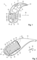
- FIG.1 A hearing instrument 2 in the form of a (BTE) hearing aid is shown roughly schematically.
- the hearing instrument 2 comprises a housing 4 to be worn behind the ear of a hearing-impaired wearer, in which the main components are two input converters 6 in the form of microphones, a signal processing unit 8 with a digital signal processor and/or a microcontroller, an output converter 10 in the form of a receiver and a rechargeable battery 12.
- the battery 12 is a Li-ion battery.
- the hearing instrument 2 also comprises a (magnetic) inductive coil 14 for sending and/or receiving magnetic alternating signals.
- the electronic frame 16 is a frame manufactured separately from the housing 4, in particular made of plastic, on which the electrical and electronic components mentioned can be pre-assembled outside the housing 4.
- the battery 12 and/or the coil 14 are preferably also fastened in or to the electronic frame 16.
- the battery 12 and the coil 14 are inserted into a recess 18 of the electronic frame 16 in such a way that that the battery 12 and the coil 14 are fixed in a defined relative position to each other and to the housing 4.
- a sound signal from the environment of the hearing instrument 2 is recorded by means of the input transducer 6 and output to the signal processing unit 8 as an audio signal (i.e. as an electrical signal carrying sound information).
- the recorded audio signal is processed by the signal processing unit 8, in particular amplified depending on the frequency in order to compensate for the wearer's hearing impairment.
- the signal processing unit 8 outputs a modified audio signal resulting from this processing to the output transducer 10. This in turn converts the modified audio signal into a sound signal.
- This sound signal (modified compared to the sound recorded from the environment) is first passed from the output transducer 10 through a sound channel 20 to a tip 22 of the housing 4, and from there through a sound tube (not explicitly shown) into the wearer's ear.
- the coil 14 is designed as an inductive transceiver for exchanging data with a second hearing instrument, whereby this second hearing instrument is worn on the other ear of the wearer.
- the coil 14 is designed for this purpose for sending and receiving magnetic alternating signals in the megahertz range (eg with a frequency of 3.3 MHz).
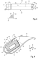
- the battery 12 is constructed in a stack design, ie as a layer stack 24. It therefore comprises a plurality of active layers 26 which are stacked on top of one another in a layering direction 28.
- the layers 26 of the battery 12 lie against one another at interfaces 30 which are parallel to a (eg in the Fig.2 and 3 shown) layering plane 32.
- This layering plane 32 is orthogonal to the layering direction 28 and is arranged in a Fig.2 and 3
- the coordinate system shown is spanned by two directions orthogonal to each other and to the layering direction 28, namely a longitudinal direction 34 and a transverse direction 36.
- the battery 12 has the shape of a cuboid with two end faces 38 and 40, which are opposite each other in the layering direction 28.
- the two end faces 38 and 40 are each aligned orthogonally to the layering direction 28 (thus parallel to the layering plane 32) and are separated by four side walls, namely two opposing broad sides 42 and 44 ( Fig.3 ) and two opposite narrow sides 46 and 48.
- the battery 12 has two electrical connection contacts 50, both of which are arranged next to each other on the front side 38.
- the assembly formed by the connection contacts 50 is also referred to collectively as contact arrangement 52 ( Fig.2 ).
- the connection contacts 50 are arranged on an edge of the front side 38, which borders on the narrow side 46 facing the tip 22 of the housing 4.
- the coil 14 is arranged adjacent to the narrow side 48 of the battery 12 facing away from the tip 22 of the housing 4. The coil 14 is thus comparatively far away from the connection contacts 50 of the battery 12.
- the coil 14 is oriented such that its axis 54 ( Fig.3 ) parallel to the transverse direction 36, and thus orthogonal to the layering direction 28 (hence parallel to the layering plane 32).
- connection contacts 50 are arranged at a distance from each other that is small compared to the longitudinal extension of the battery 12 - in the example according to Fig. 1 to 3 the distance between the connection contacts 50 measured along a connecting line 56 corresponds to only about one seventh of the longitudinal extent of the battery 12, which is formed here by the length of the edge of the battery 12 running in the longitudinal direction 34.
- the two connection contacts 50 are arranged next to one another parallel to the axis 54 of the coil 14. In other words, the connecting line 56 between the connection contacts 50 is aligned parallel to the axis 54 of the coil 14.
- the coil 14 - seen transversely to its axis 54 - is positioned centered with the contact arrangement 52, i.e.
- the geometric center 58 of the coil 14 is arranged at the same distance from both connection contacts 50 of the battery 12 and that a plane of symmetry 60 of the contact arrangement 52 that is orthogonal to the connecting line 56 intersects the coil 14 in its geometric center 58.
- the coil 14 is thus arranged such that it is arranged orthogonally and centered to the parasitic magnetic fields caused by circulating currents in the battery 12, whereby interactions of these magnetic fields with the coil 14 are excluded or at least largely reduced.
- the battery 12 In the intended wearing position of the hearing instrument 2 on the wearer's ear, the battery 12 is aligned such that its layering direction 28 is aligned exactly or at least approximately parallel to the wearer's line of sight.
- the axis 54 of the coil 14, which is perpendicular to this, is aligned exactly or at least approximately in the transverse direction of the head, and thus to the second hearing instrument worn on the wearer's other ear. This ensures effective data transmission between the two hearing instruments.
- a second embodiment of the hearing instrument 2 is shown, in which the coil 14 is designed as a telephone coil. Due to the significantly larger size of the coil 14 here and due to the desired orientation of the coil 14 in the wearing position of the hearing instrument 2, the coil 14 in the example according to Fig.4 and 5 adjacent to the broad side 44 of the battery 12. As in the previous example, the axis 54 of the coil 14 is aligned orthogonally to the layering direction 28 (and thus parallel to the layering plane 32). In addition, the distance between the connection contacts 50 is also small compared to the longitudinal extent of the battery 12 - here it corresponds to approximately one fifth of the longitudinal extent of the battery 12.
- connection contacts 50 are arranged next to each other parallel to the axis 54 of the coil 14.
- the coil 14 is again - seen transversely to its axis - positioned centered with the contact arrangement 52 (see Fig.5 ).
- the axis 54 of the coil 14, which is orthogonal to the layering direction 28 of the battery 12, is exactly or at least approximately vertical in space and thus aligned towards the ground. This enables effective reception of magnetic alternating signals emitted by induction loops - usually laid in the floor.
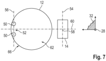
- a third embodiment of the hearing instrument 2 is shown, in which the battery 12 has a circular cylindrical shape.
- the battery 12 here again has two round end faces 62 and 64, which lie opposite one another in the layering direction 28 and are connected to one another by a peripheral wall 66.
- connection contacts 50 are arranged here on one edge of the end face 62.
- the coil 14 is arranged - opposite to the connection contacts 50 - adjacent to the peripheral wall 66, so that its axis 54 is again aligned perpendicular to the layering direction 28 of the battery 12.
- connection contacts 50 are arranged next to one another parallel to the axis 54 of the coil 14, the distance between the connection contacts 50 being small compared to the longitudinal extent of the battery 12 - it corresponds here to about a quarter of the longitudinal extent of the battery 12, the longitudinal extent being given here by the diameter.
- the coil 14 is again - seen transversely to its axis 54 - positioned centered with the contact arrangement 52 (see. Fig.7 ).
- the coil 14 is still arranged close to a base of the battery 12 (ie close to the front side 64 facing away from the connection contacts 50). In this area of the battery 12, the current density is comparatively low when the hearing instrument 2 is in operation, as a result of which the strength of the parasitic magnetic fields emitted by the battery 12 is also comparatively low. For design reasons, however, the coil 14 is arranged symmetrically in most cases.
Landscapes
- Engineering & Computer Science (AREA)
- Physics & Mathematics (AREA)
- Signal Processing (AREA)
- Acoustics & Sound (AREA)
- Chemical & Material Sciences (AREA)
- Neurosurgery (AREA)
- Health & Medical Sciences (AREA)
- Otolaryngology (AREA)
- General Health & Medical Sciences (AREA)
- Chemical Kinetics & Catalysis (AREA)
- Electrochemistry (AREA)
- General Chemical & Material Sciences (AREA)
- Manufacturing & Machinery (AREA)
- Computer Networks & Wireless Communication (AREA)
- Mechanical Engineering (AREA)
- Transportation (AREA)
- Microelectronics & Electronic Packaging (AREA)
- Materials Engineering (AREA)
- Life Sciences & Earth Sciences (AREA)
- Biophysics (AREA)
- Computer Hardware Design (AREA)
- Battery Mounting, Suspending (AREA)
- Charge And Discharge Circuits For Batteries Or The Like (AREA)
Abstract
Description
- Die Erfindung betrifft ein Hörinstrument nach dem Oberbegriff des Anspruchs 1, mit einer aufladbaren Batterie und einer (magnetisch) induktiven Sende- und/oder Empfangsspule.
- Als "Hörinstrument" werden allgemein Geräte bezeichnet, die einen Umgebungsschall aufnehmen, signaltechnisch modifizieren und ein modifiziertes Schallsignal an das Gehör einer das Hörinstrument tragenden Person ("Träger") abgeben. Ein Hörinstrument, das zur Versorgung eines hörgeschädigten Trägers ausgebildet ist und das akustische Umgebungssignale derart verarbeitet, insbesondere verstärkt, dass die Hörschädigung ganz oder teilweise kompensiert wird, wird hier und im Folgenden als "Hörgerät" bezeichnet. Ein Hörgerät umfasst hierzu üblicherweise einen Eingangswandler, beispielsweise in Form eines Mikrofons, eine Signalverarbeitungseinheit mit einem Verstärker, sowie einen Ausgangswandler. Der Ausgangswandler ist in der Regel als Miniaturlautsprecher realisiert und wird auch als "Hörer" (Receiver) bezeichnet.
- Zusätzlich zu Hörgeräten gibt es allerdings auch Hörinstrumente, die auf die Versorgung von Normalhörenden ausgerichtet sind, um das Gehör des jeweiligen Trägers zu schützen oder um die Geräuschwahrnehmung (z.B. das Sprachverständnis in komplexen Geräuschumgebungen) für bestimmte Zwecke zu unterstützen. Solche Hörinstrumente sind oft ähnlich aufgebaut wie Hörgeräte und umfassen insbesondere auch die oben genannten Komponenten Eingangswandler, Signalverarbeitung und Ausgangswandler.
- Um den zahlreichen individuellen Bedürfnissen entgegenzukommen, werden unterschiedliche Bauformen von Hörinstrumenten angeboten. Bei sogenannten BTE-Hörinstrumenten (Behind-The-Ear, auch Hinter-dem-Ohr, kurz HdO) wird ein mit dem Eingangswandler, der Signalverarbeitung und einer Batterie bestücktes Gehäuse hinter dem Ohr getragen. Je nach Ausgestaltung kann der Ausgangswandler direkt im Gehörgang des Trägers (sogenannte Ex-Hörer-Hörinstrumente oder Hörer-in-the-Canal-, kurz RIC-Hörinstrumente) angeordnet sein. Alternativ ist der Ausgangswandler innerhalb des Gehäuses selbst angeordnet. In diesem Fall leitet ein flexibler, auch als "Tube" bezeichneter Schallschlauch die akustischen Ausgabesignale des Ausgangswandlers vom Gehäuse zum Gehörgang (Schallschlauch-Hörinstrumente). Bei sogenannten ITE-Hörinstrumenten (In-the-Ear, auch In-dem-Ohr, kurz IdO) wird ein Gehäuse, welches sämtliche funktionale Komponenten einschließlich des Eingangswandlers und des Ausgangswandlers enthält, zumindest teilweise im Gehörgang getragen. Sogenannte CIC-Hörinstrumente (Completely-in-Canal) sind den ITE-Hörinstrumenten ähnlich, werden jedoch vollständig im Gehörgang getragen.
- Aufgrund der zunehmenden Anzahl der integrierten Funktionen haben Hörinstrumente einen steigenden Energiebedarf, der mit den heute üblichen Einwegbatterien nicht in zufriedenstellender Weise gedeckt werden kann.
- Es wird daher angestrebt, leistungsstarke aufladbare Batterien, insbesondere Lithium-lonen-Batterien (kurz: Li-Ionen-Batterien), als Leistungsquelle für Hörinstrumente einzusetzen. Solche aufladbaren Batterien erzeugen aber parasitäre Magnetfelder und können daher die in Hörinstrumenten, insbesondere Hörgeräten, häufig integrierten induktiven Sende- und/oder Empfangsspulen (z.B. Telefonspulen oder induktive Transceiver zur drahtlosen Kommunikation zwischen dem Hörinstrument und einem Peripheriegerät) stören. Die gleichzeitige und störungsfreie Anordnung einer aufladbaren Batterie und einer induktiven Sende- und/oder Empfangsspule in einem Hörinstrumentengehäuse ist daher kompliziert und in vielen Fällen sogar - angesichts des stark beengten Bauraums in dem Gehäuse eines Hörinstruments - unmöglich.
- Ein Hörinstrument nach dem Oberbegriff des Anspruchs 1 ist aus
US 2016/0365751 A1 bekannt. -
US 2011/097609 A1 undUS 2013/0162197 A1 offenbaren jeweils wiederaufladbare Batterien, insbesondere Lithium-Ionen-Batterien, die geschichtet sowie teilweise auch als Schichtstapel ausgebildet sind. - In H. Malecki, et al., "Lithium Ion Cell/Batteries Electromagnetic Field Reduction in Phones for Hearing Aid Compliance", Batteries 2016, Bd. 2, Nr. 2, S. 19 sind verschiedenen Bauarten von Lithium-Ionen-Batterien Im Zusammenhang mit Hörgeräten beschrieben.
- Der Erfindung liegt die Aufgabe zugrunde, eine kompakte Anordnung sowohl einer leistungsstarken aufladbaren Batterie als auch einer induktiven Sende- und/oder Empfangsspule in einem Hörinstrument zu realisieren, wobei eine unerwünschte Beeinflussung der Sende- und/oder Empfangsspule durch die Batterie unterbunden oder zumindest weitgehend reduziert sein soll.
- Diese Aufgabe wird erfindungsgemäß gelöst durch die Merkmale des Anspruchs 1. Vorteilhafte Ausführungsformen der Erfindung sind in den Unteransprüchen und der nachfolgenden Beschreibung dargelegt.
- Das Hörinstrument weist einerseits eine aufladbare Batterie und andererseits eine induktive Sende- und/oder Empfangsspule (nachfolgend kurz: Spule) auf. Erfindungsgemäß ist die Batterie in der sogenannten Stack-Bauweise, d.h. als Schichtstapel ausgebildet. In Abgrenzung von gewickelten Batterien, bei denen ein oder mehrere Schichten der Batterie um eine innere Elektrode herumgewickelt sind, umfasst die in Stack-Bauweise ausgebildete Batterie eine Mehrzahl von Schichten, die in einer Schichtungsrichtung (oder Stapelrichtung) aufeinander gestapelt sind. Als Schichtungsebene (oder Stapelebene) wird eine Ebene bezeichnet, die orthogonal (d.h. unter einem rechten Winkel) zu der Schichtungsrichtung ausgerichtet ist. Diese Schichtungsebene ist parallel zu den Grenzflächen, an denen benachbarte Schichten der in Stack-Bauweise ausgebildeten Batterie aneinanderstoßen.
- Die Spule ist dabei derart angeordnet, dass ihre Achse orthogonal zu der Schichtungsrichtung (d.h. parallel zu einer Schichtungsebene) der Batterie ausgerichtet ist. Hierdurch wird erreicht, dass die von der Batterie im Betrieb des Hörinstruments erzeugten parasitären Magnetfelder die Spule nicht oder nur in besonders geringem Maße stören. Dies wiederum ermöglicht eine besonders kompakte Anordnung der Batterie und der Spule ein einem Gehäuse des Hörinstruments. Insbesondere kann die Spule besonders nahe an der Batterie angeordnet werden, ohne dass die Funktion der Spule durch die Batterie gestört wird. Eine magnetische Abschirmung der Spule gegenüber der Batterie ist - je nach Bauform - entweder völlig unnötig und daher auch nicht vorhanden oder kann jedenfalls vergleichsweise einfach ausgebildet sein.
- Die Batterie ist vorzugsweise in Form einer Li-Ionen-Batterie ausgebildet.
- Bei der Spule handelt es sich insbesondere um eine Telefonspule (Telecoil) oder einen induktiven Transceiver. Telefonspulen sind auf den Empfang von magnetischen Wechselfeldern in dem typischen Frequenzbereich von hörbaren Schallwellen (z.B. ca. 100 Hz bis 10 kHz) ausgelegt und dienen zum Empfang von akustischer Information, die unmittelbar (beispielsweise durch in Kirchen oder Museen ausgelegte Induktionsschleifen) in magnetische Wechselfelder umgewandelt wurde. Induktive Transceiver sind auf das Senden und/oder Empfangen von magnetischen Wechselfeldern höherer Frequenzen, typischerweise in Mega-Hertz-Bereich, ausgelegt. Sie werden typischerweise zur drahtlosen Informationsübermittlung zwischen dem Hörinstrument und einem Peripheriegerät, z.B. einem weiteren Hörinstrument zur Versorgung des anderen Ohrs des Trägers, einer Fernbedienung, einem externen Audio-Schnittstellen-Gerät oder einem externen Mikrofon, eingesetzt. Die Spule kann ferner auch ein Bestandteil eines Magnetsensors, wie z.B. eines elektronischen Kompasses sein.
- Vorzugsweise ist die Batterie in dem Gehäuse des Hörgeräts derart angeordnet, dass die Schichtungsrichtung der Batterie etwa in Blickrichtung des Trägers ausgerichtet ist, wenn dieser das Hörinstrument in der bestimmungsgemäßen Position in oder am Ohr trägt. Als Blickrichtung des Trägers wird hierbei - unabhängig von der Augenstellung des Trägers - die in der Symmetrieebene des Kopfes liegende, bei gerader Kopfhaltung horizontale Richtung bezeichnet, die somit insbesondere auch orthogonal zu der Kopfquerrichtung (also der geraden Verbindung zwischen den Ohren des Trägers) ausgerichtet ist. Diese Ausrichtung der Batterie ist besonders vorteilhaft, zumal sie eine günstige, aber gleichzeitig auch störungsgeschützte Anordnung der Spule erlaubt. So ist die Spule insbesondere derart angeordnet, dass ihre Achse in der bestimmungsgemäßen Trageposition des Hörinstruments in oder am Ohr sowohl orthogonal zu der Schichtungsrichtung also auch senkrecht im umgebenden Raum (also in einem rechten Winkel zu dem Erdboden) ausgerichtet ist. Die senkrechte Ausrichtung der Spulenachse ermöglicht insbesondere einen besonders guten Empfang, wenn die Spule als Telefonspule ausgebildet ist. In einer ebenfalls vorteilhaften Alternativausführung ist die Spule derart angeordnet, dass ihre Achse in der bestimmungsgemäßen Trageposition des Hörinstruments in oder am Ohr sowohl orthogonal zu der Schichtungsrichtung also auch parallel zu der Kopfquerrichtung ausgerichtet ist. Die Ausrichtung der Spulenachse in Querrichtung ermöglicht insbesondere eine besonders effiziente Signalübertragung, wenn die Spule als induktiver Transceiver ausgebildet ist und zum Signalaustausch mit einem an dem anderen Ohr des Trägers getragenen weiteren Hörinstrument genutzt wird.
- Gemäß der üblichen Bauform weist die Batterie zwei elektrische Anschlusskontakte (Batteriepole) auf. Die aus den beiden Anschlusskontakten gebildete Baueinheit wird nachfolgend auch als "Kontaktanordnung" bezeichnet. In einer vorteilhaften Ausführungsform der Erfindung sind die beiden Anschlusskontakte in einem Abstand zueinander angeordnet, der klein gegen Längserstreckung der Batterie ist. Als Längserstreckung wird hierbei die Größe der längsten Kante oder Abmessung der Batterie verstanden. Insbesondere beträgt der Abstand der beiden Abschlusskontakte höchstens ein Drittel, vorzugsweise höchstens ein Viertel, der Längserstreckung der Batterie. In einer weiteren vorteilhaften Ausführungsform sind die beiden Anschlusskontakte parallel zu der Achse der Spule (d.h. entlang einer zu der Achse der Spule parallelen Linie) nebeneinander angeordnet.
- Die Spule ist weiterhin bevorzugt - quer zu ihrer Achse gesehen - zentriert mit der Kontaktanordnung positioniert, nämlich insbesondere derart, dass ein geometrisches Zentrum der Spule äquidistant zu beiden Anschlusskontakten der Batterie angeordnet ist.
- In zweckmäßiger Ausführung ist die Spule in der Nähe eines Bodens der Batterie, d.h. in der Nähe einer von den Abschlusskontakten abgewandten Seite der Batterie angeordnet, da hier die Stromdichte innerhalb der Batterie und insofern auch die Beeinflussung der Spule durch die Batterie besonders gering sind.
- Erfindungsgemäß weist die Batterie allgemein die Form eines geraden mathematischen Zylinders mit runden oder polygonalen Stirnflächen und mindestens einer hierzu senkrechten Seitenwand auf. Die Stirnflächen sind dabei senkrecht zu der Schichtungsrichtung (parallel zu der Schichtungsebene) ausgerichtet. Bei der vorstehend beschriebenen, zylinderförmigen Batterie sind die beiden Anschlusskontakte vorzugsweise an einer der beiden Stirnseiten angeordnet. Mit anderen Worten sind also beide Abschlusskontakte an derselben Stirnseite angeordnet.
- Erfindungsgemäß ist die Spule weiterhin benachbart zu der Seitenwand (oder einer von ggf. mehreren Seitenwänden) der Batterie angeordnet. Hierbei ist jeder der beiden Anschlusskontakte an dem von der Batterie abgewandten Rand einer zugeordneten Stirnseite angeordnet. Die (hier insbesondere wiederum auf der gleichen Stirnseite angeordneten) Anschlusskontakte sind somit besonders weit von der Spule entfernt, wodurch die Wahrscheinlichkeit einer Störung der Spule durch die Batterie weiter reduziert wird.
- Die vorstehend beschriebene Erfindung wird bevorzugt bei einem BTE-Hörinstrument eingesetzt. Die Batterie und die Spule sind in diesem Fall in einem hinter dem Ohr des Trägers zu tragenden Gehäuse angeordnet. Grundsätzlich kann die Erfindung aber auch bei anders gebauten Hörinstrumenten, insbesondere ITE-Hörinstrumenten oder (ganz oder teilweise) implantierten Hörinstrumenten, eingesetzt werden.
- Bei dem Hörinstrument handelt es sich insbesondere um ein - wie eingangs beschrieben aufgebautes - Hörgerät zur Versorgung eines hörgeschädigten Trägers. Zusätzlich zu der Batterie, der Spule und dem Gehäuse weist das Hörinstrument vorzugsweise mindestens einen Eingangswandler (beispielsweise in Form eines Mikrofons), eine Signalverarbeitungseinheit mit einem (insbesondere digitalen) Signalprozessor und/oder einem Verstärker sowie einen Ausgangswandler (insbesondere einen Hörer), auf. Der Ausgangswandler ist dabei wahlweise in dem Gehäuse integriert oder in einem von dem Gehäuse getrennten Ohrstück angeordnet.
- Nachfolgend werden Ausführungsbeispiele der Erfindung anhand einer Zeichnung näher erläutert. Darin zeigen:
- Fig. 1
- in schematischer Darstellung ein Hörinstrument mit einem Gehäuse, einem Eingangswandler in Form eines Mikrofons, einer Signalverarbeitungseinheit, einem Ausgangswandler in Form eines Hörers sowie mit einer aufladbaren Batterie und einer induktiven (Sende- und/oder Empfangs-)Spule,
- Fig. 2
- in perspektivischer Darstellung einen in dem Gehäuse angeordneten Elektronikrahmen des Hörinstruments gemäß
Fig. 1 sowie die hier quaderförmige Batterie und die Spule in einer ersten Anordnung, - Fig. 3
- in Draufsicht auf eine zwei Anschlusskontakte tragende Stirnseite der Batterie die Anordnung der Batterie und der Spule gemäß
Fig. 2 , - Fig. 4
- in Darstellung gemäß
Fig. 2 den Elektronikrahmen sowie die hier ebenfalls quaderförmige Batterie und die Spule des Hörinstruments gemäßFig. 1 in einer zweiten Anordnung, - Fig. 5
- in Darstellung gemäß
Fig. 3 die Anordnung der Batterie und der Spule gemäßFig. 4 , - Fig. 6
- in perspektivischer Darstellung die hier kreiszylinderförmige Batterie und die bezüglich dieser Batterie positionierte Spule, und
- Fig. 7
- in Darstellung gemäß
Fig. 3 die Anordnung der Batterie und der Spule gemäßFig. 6 . - Einander entsprechende Teile und Größen sind stets mit gleichen Bezugszeichen versehen.
- In
Fig. 1 ist grob schematisch ein Hörinstrument 2 in Form eines (BTE-)Hörgeräts dargestellt. - Das Hörinstrument 2 umfasst ein hinter dem Ohr eines hörgeschädigten Trägers zu tragendes Gehäuse 4, in welchem als Hauptkomponenten zwei Eingangswandler 6 in Form von Mikrofonen, eine Signalverarbeitungseinheit 8 mit einem digitalen Signalprozessor und/oder einem Mikrocontroller, ein Ausgangswandler 10 in Form eines Hörers sowie eine aufladbare Batterie 12 angeordnet sind. Bei der Batterie 12 handelt es sich um eine Li-Ionen-Batterie. Das Hörinstrument 2 umfasst weiterhin eine (magnetisch) induktive Spule 14 zum Senden und/oder Empfangen von magnetischen Wechselsignalen.
- Ein Großteil der elektrischen und elektronischen Komponenten des Hörinstruments 2, insbesondere die Eingangswandler 6, die Signalverarbeitungseinheit 8 und der Ausgangswandler 8, sind an einem Elektronikrahmen 16 montiert. Bei dem Elektronikrahmen 16 handelt es sich um ein separat von dem Gehäuse 4 gefertigtes Gerüst, insbesondere aus Kunststoff, an dem die genannten elektrischen und elektronischen Komponenten außerhalb des Gehäuses 4 vormontiert werden können. Die Batterie 12 und/oder die Spule 14 sind vorzugsweise ebenfalls in oder an dem Elektronikrahmen 16 befestigt. Insbesondere sind die Batterie 12 und die Spule 14 in eine Aussparung 18 des Elektronikrahmens 16 derart eingelegt, dass die Batterie 12 und die Spule 14 in einer definierten Relativposition zueinander und zu dem Gehäuse 4 fixiert sind.
- Im Betrieb der Hörvorrichtung 2 wird mittels der Eingangswandler 6 ein Schallsignal aus der Umgebung des Hörinstruments 2 aufgenommen und als Audiosignal (d.h. als eine Schallinformation tragendes elektrisches Signal) an die Signalverarbeitungseinheit 8 ausgegeben. Durch die Signalverarbeitungseinheit 8 wird das aufgenommene Audiosignal verarbeitet, insbesondere frequenzabhängig verstärkt, um die Hörschädigung des Trägers zu kompensieren. Die Signalverarbeitungseinheit 8 gibt ein aus dieser Verarbeitung resultierendes modifiziertes Audiosignal an den Ausgangswandler 10 aus. Dieser wandelt das modifizierte Audiosignal wiederum in ein Schallsignal um. Dieses (gegenüber dem aus der Umgebung aufgenommenen Schall modifizierte) Schallsignal wird von dem Ausgangswandler 10 zunächst durch einen Schallkanal 20 an eine Spitze 22 des Gehäuses 4, und von dort durch einen nicht explizit dargestellten Schallschlauch in das Ohr des Trägers geleitet.
- In der Ausführungsform gemäß
Fig. 1 ist die Spule 14 als induktiver Transceiver zum Datenaustausch mit einem zweiten Hörinstrument ausgebildet, wobei dieses zweite Hörinstrument an dem anderen Ohr des Trägers getragen wird. Die Spule 14 ist hierzu zum Senden und Empfangen von magnetischen Wechselsignalen im Mega-Hertz-Bereich (z.B. mit einer Frequenz von 3,3 MHz) ausgebildet. - Die Batterie 12 ist in Stack-Bauweise, d.h. als Schichtstapel 24 aufgebaut. Sie umfasst demnach eine Mehrzahl von aktiven Schichten 26, die in einer Schichtungsrichtung 28 aufeinandergestapelt sind. Die Schichten 26 der Batterie 12 liegen dabei an Grenzflächen 30 aneinander, die parallel zu einer (z.B. in den
Fig. 2 und3 dargestellten) Schichtungsebene 32 ausgerichtet sind. Diese Schichtungsebene 32 steht orthogonal auf die Schichtungsrichtung 28 und wird in einem in denFig. 2 und3 dargestellten Koordinatensystem aufgespannt durch zwei zueinander und zu der Schichtungsrichtung 28 orthogonale Richtungen, nämlich eine Längsrichtung 34 und eine Querrichtung 36. - In dem in den
Fig. 1 bis 3 dargestellten Ausführungsbeispiel hat die Batterie 12 die Form eines Quaders mit zwei Stirnseiten 38 und 40, die in Schichtungsrichtung 28 einander gegenüberliegen. Die beiden Stirnseiten 38 und 40 sind jeweils orthogonal zu der Schichtungsrichtung 28 (mithin parallel zu der Schichtungsebene 32) ausgerichtet und werden durch vier Seitenwände, nämlich zwei einander gegenüberliegende Breitseiten 42 und 44 (Fig. 3 ) sowie zwei einander gegenüberliegende Schmalseiten 46 und 48 verbunden. - Die Batterie 12 hat zwei elektrische Anschlusskontakte 50, die beide nebeneinander an der Stirnseite 38 angeordnet sind. Die durch die Anschlusskontakte 50 gebildet Baugruppe ist zusammenfassend auch als Kontaktanordnung 52 (
Fig. 2 ) bezeichnet. Die Anschlusskontakte 50 sind hierbei an einem Rand der Stirnseite 38 angeordnet, der an die der Spitze 22 des Gehäuses 4 zugewandte Schmalseite 46 angrenzt. - Um eine unerwünschte Beeinflussung der Spule 14 durch die von der Batterie 12 im Betrieb des Hörinstruments 2 erzeugten parasitären Magnetfelder zu vermeiden oder zumindest möglichst gering zu halten, ist die Spule 14 benachbart zu der von der Spitze 22 des Gehäuses 4 abgewandten Schmalseite 48 der Batterie 12 angeordnet. Die Spule 14 ist somit vergleichsweise weit von den Anschlusskontakten 50 der Batterie 12 entfernt. Zudem ist die Spule 14 derart orientiert, dass ihre Achse 54 (
Fig. 3 ) parallel zu der Querrichtung 36, und damit orthogonal zu der Schichtungsrichtung 28 (mithin parallel zu der Schichtungsebene 32) ausgerichtet ist. - Eine Beeinflussung der Spule 14 durch die Batterie 12 wird weiter dadurch reduziert, dass die beiden Anschlusskontakte 50 in einem Abstand zueinander angeordnet, der klein gegen Längserstreckung der Batterie 12 ist - in dem Beispiel gemäß
Fig. 1 bis 3 entspricht der entlang einer Verbindungslinie 56 gemessene Abstand zwischen den Anschlusskontakten 50 nur etwa einem Siebtel der Längserstreckung der Batterie 12, die hier durch die Länge der in Längsrichtung 34 verlaufenden Kante der Batterie 12 gebildet ist. Des Weiteren sind die beiden Anschlusskontakte 50 parallel zu der Achse 54 der Spule 14 nebeneinander angeordnet. Mit anderen Worten ist die Verbindungslinie 56 zwischen den Anschlusskontakten 50 parallel zu der Achse 54 der Spule 14 ausgerichtet. Schließlich ist die Spule 14 - quer zu ihrer Achse 54 gesehen - zentriert mit der Kontaktanordnung 52 positioniert, also derart, dass das geometrische Zentrum 58 der Spule 14 in gleichem Abstand zu beiden Anschlusskontakten 50 der Batterie 12 angeordnet ist und dass eine zu der Verbindungslinie 56 orthogonale Symmetrieebene 60 der Kontaktanordnung 52 die Spule 14 in ihre geometrischen Zentrum 58 schneidet. Somit ist die Spule 14 derart angeordnet, dass sie zu den durch Kreisströme in der Batterie 12 verursachten parasitären Magnetfeldern orthogonal und zentriert angeordnet ist, wodurch Wechselwirkungen dieser Magnetfelder mit der Spule 14 ausgeschlossen oder zumindest weitgehend reduziert sind. - In der bestimmungsgemäßen Trageposition des Hörinstruments 2 an dem Ohr des Trägers ist die Batterie 12 derart ausgerichtet, dass ihre Schichtungsrichtung 28 exakt oder zumindest näherungsweise parallel zu der Blickrichtung des Trägers ausgerichtet ist. Die hierzu senkrechte Achse 54 der Spule 14 ist dabei exakt oder zumindest näherungsweise in Kopfquerrichtung, und somit auf das an dem anderen Ohr des Trägers getragene zweite Hörinstrument ausgerichtet. Somit wird eine effektive Datenübertragung zwischen den beiden Hörinstrumenten sichergestellt.
- In den
Fig. 4 und5 ist eine zweite Ausführungsform des Hörinstruments 2 dargestellt, bei der die Spule 14 als Telefonspule ausgebildet ist. Aufgrund der hier wesentlich größeren Baugröße der Spule 14 sowie aufgrund der gewünschten Ausrichtung der Spule 14 in der Trageposition des Hörinstruments 2 ist die Spule 14 im Beispiel gemäßFig. 4 und5 benachbart zu der Breitseite 44 der Batterie 12 angeordnet. Wie im voranstehenden Beispiel ist die Achse 54 der Spule 14 dabei orthogonal zu der Schichtungsrichtung 28 (mithin parallel zu der Schichtungsebene 32) ausgerichtet. Zudem ist auch hier der Abstand der Anschlusskontakte 50 klein gegen Längserstreckung der Batterie 12 - er entspricht hier etwa einem Fünftel der Längserstreckung der Batterie 12. - Zudem sind auch im Beispiel gemäß
Fig. 4 und5 die beiden Anschlusskontakte 50 parallel zu der Achse 54 der Spule 14 nebeneinander angeordnet. Ebenso ist die Spule 14 wiederum - quer zu ihrer Achse gesehen - zentriert mit der Kontaktanordnung 52 positioniert (s.Fig. 5 ). - In der bestimmungsgemäßen Trageposition des Hörinstruments 2 ist die zu der Schichtungsrichtung 28 der Batterie 12 orthogonale Achse 54 des Spule 14 exakt oder zumindest näherungsweise senkrecht im Raum, und somit auf den Erdboden hin ausgerichtet. Somit wird ein effektiver Empfang von magnetischen Wechselsignalen ermöglicht, die von - üblicherweise in Böden verlegten - Induktionsschleifen emittiert werden.
- In den
Fig. 6 und7 ist eine dritte Ausführungsform des Hörinstruments 2 dargestellt, bei der die Batterie 12 eine kreiszylindrische Form hat. Die Batterie 12 weist hier wiederum zwei runde Stirnseiten 62 und 64 auf, die in Schichtungsrichtung 28 einander gegenüberliegen und durch eine Umfangswand 66 miteinander verbunden werden. - Die beiden Anschlusskontakte 50 sind hier an einem Rand der Stirnfläche 62 angeordnet. Die Spule 14 ist - entgegengesetzt zu den Anschlusskontakten 50 - benachbart zu der Umfangswand 66 angeordnet, so dass ihre Achse 54 wiederum senkrecht zu der Schichtungsrichtung 28 der Batterie 12 ausgerichtet ist.
- Wie in den voranstehenden Ausführungsbeispielen sind auch im Beispiel gemäß
Fig. 6 und7 die beiden Anschlusskontakte 50 parallel zu der Achse 54 der Spule 14 nebeneinander angeordnet, wobei der Abstand zwischen den Anschlusskontakten 50 wiederum klein gegenüber der Längserstreckung der Batterie 12 ist - er entspricht hier etwa einem Viertel der Längserstreckung der Batterie 12, wobei die Längserstreckung hier durch den Durchmesser gegeben ist. Ebenso ist die Spule 14 wiederum - quer zu ihrer Achse 54 gesehen - zentriert mit der Kontaktanordnung 52 positioniert (s.Fig. 7 ). - Wie aus
Fig. 6 erkennbar ist, ist die Spule 14 hier weiterhin nahe an einem Boden der Batterie 12 (d.h. nahe an der von den Anschlusskontakten 50 abgewandten Stirnseite 64) angeordnet. In diesem Bereich der Batterie 12 ist im Betrieb des Hörinstruments 2 die Stromdichte vergleichsweise gering, wodurch hier auch die Stärke der von der Batterie 12 emittierten parasitären Magnetfelder vergleichsweise gering ist. Aus Designgründen wird die Spule 14 in den meisten Fällen aber symmetrisch angeordnet. - Die Erfindung wird anhand der vorstehend beschriebenen Ausführungsbeispiele besonders deutlich. Sie ist gleichwohl auf diese Ausführungsbeispiele aber nicht beschränkt. Vielmehr können weitere Ausführungsformen der Erfindung aus den Ansprüchen und der Beschreibung abgleitet werden.
-
- 2
- Hörinstrument
- 4
- Gehäuse
- 6
- Eingangswandler
- 8
- Signalverarbeitungseinheit
- 10
- Ausgangswandler
- 12
- Batterie
- 14
- Spule
- 16
- Elektronikrahmen
- 18
- Aussparung
- 20
- Schallkanal
- 22
- Spitze
- 24
- Schichtstapel
- 26
- Schicht
- 28
- Schichtungsrichtung
- 30
- Grenzfläche
- 32
- Schichtungsebene
- 34
- Längsrichtung
- 36
- Querrichtung
- 38
- Stirnseite
- 40
- Stirnseite
- 42
- Breitseite
- 44
- Breitseite
- 46
- Schmalseite
- 48
- Schmalseite
- 50
- Anschlusskontakt
- 52
- Kontaktanordnung
- 54
- Achse
- 56
- Verbindungslinie
- 58
- Zentrum
- 60
- Symmetrieebene
- 62
- Stirnseite
- 64
- Stirnseite
- 66
- Umfangswand
Claims (8)
- Hörinstrument (2) mit einer aufladbaren Batterie (12) und einer induktiven Sende- und/oder Empfangsspule (14), wobei die Batterie (12) als Schichtstapel (24) ausgebildet ist und eine Kontaktanordnung (52) mit zwei elektrischen Anschlusskontakten (50) aufweist, und wobei die Batterie (12) die Form eines allgemeinen geraden Zylinders mit zwei in Schichtungsrichtung (28) einander gegenüberliegenden, kreisförmigen oder polygonalen Stirnseiten (38, 40, 62, 64) und mindestens einer hierzu senkrechten Seitenwand (42, 44, 46, 48, 66) aufweist,
dadurch gekennzeichnet,- dass die Sende- und/oder Empfangsspule (14) derart angeordnet ist, dass ihre Achse (54) senkrecht zu einer Schichtungsrichtung (28) der Batterie (12) ausgerichtet ist, und- wobei die Sende- und/oder Empfangsspule (14) benachbart zu der Seitenwand (66) oder einer Seitenwand (48) von mehreren Seitenwänden (42, 44, 46, 48) der Batterie (12) angeordnet ist, und jeder der beiden Anschlusskontakte (50) an einem von der Batterie (12) abgewandten Rand einer zugeordneten Stirnseite (38, 62) angeordnet ist. - Hörinstrument (2) nach Anspruch 1,
wobei die Batterie (12) in einem Gehäuse (4) des Hörinstruments (2) derart angeordnet ist, dass die Schichtungsrichtung (28) exakt oder näherungsweise parallel zu der Blickrichtung einer Person ausgerichtet ist, die das Hörinstrument (2) in einer bestimmungsgemäßen Trageposition in oder an einem ihrer Ohren trägt. - Hörinstrument (2) nach Anspruch 1 oder 2,
wobei die beiden Anschlusskontakte (50) in einem Abstand zu einander angeordnet sind, der höchstens ein Drittel, vorzugsweise höchstens ein Viertel, der Längserstreckung der Batterie (12) beträgt. - Hörinstrument (2) nach einem der Ansprüche 1 bis 3,
wobei die beiden Anschlusskontakte (50) parallel zu der Achse (54) der Sende- und/oder Empfangsspule (14) nebeneinander angeordnet sind. - Hörinstrument (2) nach einem der Ansprüche 1 bis 4,
wobei die Sende- und/oder Empfangsspule (14), quer zu ihrer Achse (54) gesehen, zentriert mit der Kontaktanordnung (52) positioniert ist. - Hörinstrument (2) nach einem der Ansprüche 1 bis 5,
wobei die beiden Anschlusskontakte (50) an einer der beiden Stirnseiten (38, 40, 62, 64) angeordnet sind. - Hörinstrument (2) nach einem der Ansprüche 1 bis 6,
mit einem hinter dem Ohr einer Person zu tragenden Gehäuse (4), in dem die Batterie (12) und die Sende- und/oder Empfangsspule (14) angeordnet sind. - Hörinstrument (2) nach einem der Ansprüche 1 bis 7,
wobei die Batterie (12) eine Li-Ionen-Batterie ist.
Applications Claiming Priority (2)
| Application Number | Priority Date | Filing Date | Title |
|---|---|---|---|
| DE102019207008.6A DE102019207008A1 (de) | 2019-05-14 | 2019-05-14 | Hörinstrument |
| EP20159933.9A EP3739906B1 (de) | 2019-05-14 | 2020-02-27 | Hörinstrument |
Related Parent Applications (1)
| Application Number | Title | Priority Date | Filing Date |
|---|---|---|---|
| EP20159933.9A Division EP3739906B1 (de) | 2019-05-14 | 2020-02-27 | Hörinstrument |
Publications (2)
| Publication Number | Publication Date |
|---|---|
| EP4425665A2 true EP4425665A2 (de) | 2024-09-04 |
| EP4425665A3 EP4425665A3 (de) | 2024-11-27 |
Family
ID=72800808
Family Applications (2)
| Application Number | Title | Priority Date | Filing Date |
|---|---|---|---|
| EP24190202.2A Pending EP4425665A3 (de) | 2019-05-14 | 2020-02-27 | Hörinstrument |
| EP20159933.9A Active EP3739906B1 (de) | 2019-05-14 | 2020-02-27 | Hörinstrument |
Family Applications After (1)
| Application Number | Title | Priority Date | Filing Date |
|---|---|---|---|
| EP20159933.9A Active EP3739906B1 (de) | 2019-05-14 | 2020-02-27 | Hörinstrument |
Country Status (4)
| Country | Link |
|---|---|
| US (1) | US20200367000A1 (de) |
| EP (2) | EP4425665A3 (de) |
| CN (1) | CN111954140A (de) |
| DE (1) | DE102019207008A1 (de) |
Families Citing this family (1)
| Publication number | Priority date | Publication date | Assignee | Title |
|---|---|---|---|---|
| US12046914B2 (en) | 2021-06-07 | 2024-07-23 | Gn Hearing A/S | Wirelessly rechargeable in-ear hearing device and charger for same |
Citations (3)
| Publication number | Priority date | Publication date | Assignee | Title |
|---|---|---|---|---|
| US20110097609A1 (en) | 2000-03-24 | 2011-04-28 | Cymbet Corporation | Method and apparatus for integrated-circuit battery devices |
| US20130162197A1 (en) | 2011-12-23 | 2013-06-27 | Semiconductor Energy Laboratory Co., Ltd. | Method for charging lithium ion secondary battery and battery charger |
| US20160365751A1 (en) | 2014-02-24 | 2016-12-15 | Nitto Denko Corporation | Power source device for portable apparatus, portable apparatus, and charging device |
Family Cites Families (4)
| Publication number | Priority date | Publication date | Assignee | Title |
|---|---|---|---|---|
| JP6513895B2 (ja) * | 2013-02-20 | 2019-05-15 | 日東電工株式会社 | 携帯機器及びその充電機器、携帯機器充電システム |
| WO2017116791A1 (en) * | 2015-12-30 | 2017-07-06 | Earlens Corporation | Light based hearing systems, apparatus and methods |
| US11206499B2 (en) * | 2016-08-18 | 2021-12-21 | Qualcomm Incorporated | Hearable device comprising integrated device and wireless functionality |
| CN109037501A (zh) * | 2018-08-30 | 2018-12-18 | 深圳市能锐创新科技有限公司 | 扣式锂离子电池壳体及扣式叠片锂离子电池 |
-
2019
- 2019-05-14 DE DE102019207008.6A patent/DE102019207008A1/de active Pending
-
2020
- 2020-02-27 EP EP24190202.2A patent/EP4425665A3/de active Pending
- 2020-02-27 EP EP20159933.9A patent/EP3739906B1/de active Active
- 2020-04-30 US US16/863,050 patent/US20200367000A1/en not_active Abandoned
- 2020-05-07 CN CN202010376583.3A patent/CN111954140A/zh active Pending
Patent Citations (3)
| Publication number | Priority date | Publication date | Assignee | Title |
|---|---|---|---|---|
| US20110097609A1 (en) | 2000-03-24 | 2011-04-28 | Cymbet Corporation | Method and apparatus for integrated-circuit battery devices |
| US20130162197A1 (en) | 2011-12-23 | 2013-06-27 | Semiconductor Energy Laboratory Co., Ltd. | Method for charging lithium ion secondary battery and battery charger |
| US20160365751A1 (en) | 2014-02-24 | 2016-12-15 | Nitto Denko Corporation | Power source device for portable apparatus, portable apparatus, and charging device |
Non-Patent Citations (1)
| Title |
|---|
| H. MALECKI ET AL.: "Lithium Ion Cell/Batteries Electromagnetic Field Reduction in Phones for Hearing Aid Compliance", BATTERIES, 2016, pages 19 |
Also Published As
| Publication number | Publication date |
|---|---|
| DE102019207008A1 (de) | 2020-11-19 |
| US20200367000A1 (en) | 2020-11-19 |
| EP4425665A3 (de) | 2024-11-27 |
| EP3739906B1 (de) | 2024-08-14 |
| CN111954140A (zh) | 2020-11-17 |
| EP3739906C0 (de) | 2024-08-14 |
| EP3739906A1 (de) | 2020-11-18 |
Similar Documents
| Publication | Publication Date | Title |
|---|---|---|
| EP2811761B1 (de) | Antenneneinrichtung für Hörinstrumente | |
| EP2770753B1 (de) | Kabelloses Ladesystem für Hörinstrumente | |
| EP2894880B1 (de) | Antenneneinrichtung für Hörinstrumente | |
| EP3413587B1 (de) | Hörgerät, insbesondere hinter-dem-ohr-hörhilfegerät | |
| EP1962557B1 (de) | Hörvorrichtung mit einem speziellen Energieaufnahmesystem und entsprechendes Verfahren | |
| EP2932559B1 (de) | Modulare antenne für hörgeräte | |
| EP3579336B1 (de) | Antenne sowie gerät mit einer solchen antenne | |
| DE102013204681B4 (de) | Binaurales Hörinstrument sowie Ohrstück | |
| EP3491846B1 (de) | Hörhilfegerät und hörhilfevorrichtung | |
| EP3567672A1 (de) | Hörhilfegerät mit elektronikrahmen und darin integrierter antenne | |
| EP3209032B1 (de) | Lautsprechermodul für ein hörgerät und hörgerät | |
| EP1944850A2 (de) | Ladevorrichtung für ein Hörgerät, Hörgerät und Hörgerätefernbedienung | |
| EP3809723A1 (de) | Hörinstrument | |
| DE102021201095A1 (de) | Platzsparende Antenne für ein Hörinstrument | |
| EP3614494B1 (de) | Performante magnetisch induktive antenne für ein hörinstrument | |
| EP3739906B1 (de) | Hörinstrument | |
| EP0660642B1 (de) | Am Kopf tragbares Hörgerät | |
| EP2053878B1 (de) | Hörvorrichtung mit Nutzung eines induktiven Schaltreglers als Funksender | |
| WO2018024392A1 (de) | Hörgerät mit rf-antenne | |
| DE102020205153A1 (de) | Batteriemodul und Hörvorrichtung | |
| DE102017012195B4 (de) | Hörgerät, insbesondere Hinter-dem-Ohr-Hörhilfegerät | |
| DE102020205155A1 (de) | Batteriemodul und Hörvorrichtung | |
| DE102014219017A1 (de) | Hörinstrument mit Energieversorgungseinrichtung und Hörinstrumentensystem mit Energieversorgungseinrichtung | |
| DE102006049469B4 (de) | Hörgerät mit stromführendem Metallbügel | |
| DE102017220187A1 (de) | Hörhilfegerät |
Legal Events
| Date | Code | Title | Description |
|---|---|---|---|
| PUAI | Public reference made under article 153(3) epc to a published international application that has entered the european phase |
Free format text: ORIGINAL CODE: 0009012 |
|
| STAA | Information on the status of an ep patent application or granted ep patent |
Free format text: STATUS: THE APPLICATION HAS BEEN PUBLISHED |
|
| AC | Divisional application: reference to earlier application |
Ref document number: 3739906 Country of ref document: EP Kind code of ref document: P |
|
| AK | Designated contracting states |
Kind code of ref document: A2 Designated state(s): AL AT BE BG CH CY CZ DE DK EE ES FI FR GB GR HR HU IE IS IT LI LT LU LV MC MK MT NL NO PL PT RO RS SE SI SK SM TR |
|
| REG | Reference to a national code |
Ref country code: DE Ref legal event code: R079 Free format text: PREVIOUS MAIN CLASS: H01M0050247000 Ipc: H04R0025000000 |
|
| PUAL | Search report despatched |
Free format text: ORIGINAL CODE: 0009013 |
|
| AK | Designated contracting states |
Kind code of ref document: A3 Designated state(s): AL AT BE BG CH CY CZ DE DK EE ES FI FR GB GR HR HU IE IS IT LI LT LU LV MC MK MT NL NO PL PT RO RS SE SI SK SM TR |
|
| RIC1 | Information provided on ipc code assigned before grant |
Ipc: H01M 10/0525 20100101ALN20241023BHEP Ipc: H01M 50/247 20210101ALI20241023BHEP Ipc: H01M 50/213 20210101ALI20241023BHEP Ipc: H01M 10/46 20060101ALI20241023BHEP Ipc: H01M 10/42 20060101ALI20241023BHEP Ipc: B60T 13/74 20060101ALI20241023BHEP Ipc: B60T 13/68 20060101ALI20241023BHEP Ipc: B60T 13/14 20060101ALI20241023BHEP Ipc: H04R 25/00 20060101AFI20241023BHEP |
|
| STAA | Information on the status of an ep patent application or granted ep patent |
Free format text: STATUS: REQUEST FOR EXAMINATION WAS MADE |
|
| 17P | Request for examination filed |
Effective date: 20250417 |
|
| GRAP | Despatch of communication of intention to grant a patent |
Free format text: ORIGINAL CODE: EPIDOSNIGR1 |
|
| STAA | Information on the status of an ep patent application or granted ep patent |
Free format text: STATUS: GRANT OF PATENT IS INTENDED |
|
| RIC1 | Information provided on ipc code assigned before grant |
Ipc: H04R 25/00 20060101AFI20260212BHEP Ipc: B60T 13/14 20060101ALI20260212BHEP Ipc: B60T 13/68 20060101ALI20260212BHEP Ipc: B60T 13/74 20060101ALI20260212BHEP Ipc: H01M 10/42 20060101ALI20260212BHEP Ipc: H01M 10/46 20060101ALI20260212BHEP Ipc: H01M 50/213 20210101ALI20260212BHEP Ipc: H01M 50/247 20210101ALI20260212BHEP Ipc: H01M 10/0525 20100101ALN20260212BHEP |
|
| INTG | Intention to grant announced |
Effective date: 20260227 |
|
| GRAS | Grant fee paid |
Free format text: ORIGINAL CODE: EPIDOSNIGR3 |
|
| GRAA | (expected) grant |
Free format text: ORIGINAL CODE: 0009210 |
|
| STAA | Information on the status of an ep patent application or granted ep patent |
Free format text: STATUS: THE PATENT HAS BEEN GRANTED |