EP4425677A1 - Bloc-batterie et dispositif le comprenant - Google Patents
Bloc-batterie et dispositif le comprenant Download PDFInfo
- Publication number
- EP4425677A1 EP4425677A1 EP23843264.5A EP23843264A EP4425677A1 EP 4425677 A1 EP4425677 A1 EP 4425677A1 EP 23843264 A EP23843264 A EP 23843264A EP 4425677 A1 EP4425677 A1 EP 4425677A1
- Authority
- EP
- European Patent Office
- Prior art keywords
- battery
- cell
- battery cells
- cover
- battery pack
- Prior art date
- Legal status (The legal status is an assumption and is not a legal conclusion. Google has not performed a legal analysis and makes no representation as to the accuracy of the status listed.)
- Pending
Links
Images



Classifications
-
- H—ELECTRICITY
- H01—ELECTRIC ELEMENTS
- H01M—PROCESSES OR MEANS, e.g. BATTERIES, FOR THE DIRECT CONVERSION OF CHEMICAL ENERGY INTO ELECTRICAL ENERGY
- H01M50/00—Constructional details or processes of manufacture of the non-active parts of electrochemical cells other than fuel cells, e.g. hybrid cells
- H01M50/30—Arrangements for facilitating escape of gases
- H01M50/35—Gas exhaust passages comprising elongated, tortuous or labyrinth-shaped exhaust passages
- H01M50/358—External gas exhaust passages located on the battery cover or case
-
- H—ELECTRICITY
- H01—ELECTRIC ELEMENTS
- H01M—PROCESSES OR MEANS, e.g. BATTERIES, FOR THE DIRECT CONVERSION OF CHEMICAL ENERGY INTO ELECTRICAL ENERGY
- H01M10/00—Secondary cells; Manufacture thereof
- H01M10/05—Accumulators with non-aqueous electrolyte
- H01M10/052—Li-accumulators
- H01M10/0525—Rocking-chair batteries, i.e. batteries with lithium insertion or intercalation in both electrodes; Lithium-ion batteries
-
- H—ELECTRICITY
- H01—ELECTRIC ELEMENTS
- H01M—PROCESSES OR MEANS, e.g. BATTERIES, FOR THE DIRECT CONVERSION OF CHEMICAL ENERGY INTO ELECTRICAL ENERGY
- H01M50/00—Constructional details or processes of manufacture of the non-active parts of electrochemical cells other than fuel cells, e.g. hybrid cells
- H01M50/10—Primary casings; Jackets or wrappings
- H01M50/183—Sealing members
- H01M50/184—Sealing members characterised by their shape or structure
-
- H—ELECTRICITY
- H01—ELECTRIC ELEMENTS
- H01M—PROCESSES OR MEANS, e.g. BATTERIES, FOR THE DIRECT CONVERSION OF CHEMICAL ENERGY INTO ELECTRICAL ENERGY
- H01M50/00—Constructional details or processes of manufacture of the non-active parts of electrochemical cells other than fuel cells, e.g. hybrid cells
- H01M50/20—Mountings; Secondary casings or frames; Racks, modules or packs; Suspension devices; Shock absorbers; Transport or carrying devices; Holders
- H01M50/204—Racks, modules or packs for multiple batteries or multiple cells
- H01M50/207—Racks, modules or packs for multiple batteries or multiple cells characterised by their shape
- H01M50/211—Racks, modules or packs for multiple batteries or multiple cells characterised by their shape adapted for pouch cells
-
- H—ELECTRICITY
- H01—ELECTRIC ELEMENTS
- H01M—PROCESSES OR MEANS, e.g. BATTERIES, FOR THE DIRECT CONVERSION OF CHEMICAL ENERGY INTO ELECTRICAL ENERGY
- H01M50/00—Constructional details or processes of manufacture of the non-active parts of electrochemical cells other than fuel cells, e.g. hybrid cells
- H01M50/20—Mountings; Secondary casings or frames; Racks, modules or packs; Suspension devices; Shock absorbers; Transport or carrying devices; Holders
- H01M50/271—Lids or covers for the racks or secondary casings
- H01M50/273—Lids or covers for the racks or secondary casings characterised by the material
- H01M50/276—Inorganic material
-
- H—ELECTRICITY
- H01—ELECTRIC ELEMENTS
- H01M—PROCESSES OR MEANS, e.g. BATTERIES, FOR THE DIRECT CONVERSION OF CHEMICAL ENERGY INTO ELECTRICAL ENERGY
- H01M50/00—Constructional details or processes of manufacture of the non-active parts of electrochemical cells other than fuel cells, e.g. hybrid cells
- H01M50/30—Arrangements for facilitating escape of gases
- H01M50/342—Non-re-sealable arrangements
-
- H—ELECTRICITY
- H01—ELECTRIC ELEMENTS
- H01M—PROCESSES OR MEANS, e.g. BATTERIES, FOR THE DIRECT CONVERSION OF CHEMICAL ENERGY INTO ELECTRICAL ENERGY
- H01M50/00—Constructional details or processes of manufacture of the non-active parts of electrochemical cells other than fuel cells, e.g. hybrid cells
- H01M50/30—Arrangements for facilitating escape of gases
- H01M50/383—Flame arresting or ignition-preventing means
-
- H—ELECTRICITY
- H01—ELECTRIC ELEMENTS
- H01M—PROCESSES OR MEANS, e.g. BATTERIES, FOR THE DIRECT CONVERSION OF CHEMICAL ENERGY INTO ELECTRICAL ENERGY
- H01M2220/00—Batteries for particular applications
- H01M2220/20—Batteries in motive systems, e.g. vehicle, ship, plane
-
- Y—GENERAL TAGGING OF NEW TECHNOLOGICAL DEVELOPMENTS; GENERAL TAGGING OF CROSS-SECTIONAL TECHNOLOGIES SPANNING OVER SEVERAL SECTIONS OF THE IPC; TECHNICAL SUBJECTS COVERED BY FORMER USPC CROSS-REFERENCE ART COLLECTIONS [XRACs] AND DIGESTS
- Y02—TECHNOLOGIES OR APPLICATIONS FOR MITIGATION OR ADAPTATION AGAINST CLIMATE CHANGE
- Y02E—REDUCTION OF GREENHOUSE GAS [GHG] EMISSIONS, RELATED TO ENERGY GENERATION, TRANSMISSION OR DISTRIBUTION
- Y02E60/00—Enabling technologies; Technologies with a potential or indirect contribution to GHG emissions mitigation
- Y02E60/10—Energy storage using batteries
Definitions
- the present invention relates to a battery pack and a device including the same, and more particularly, a battery pack improved in energy density and cooling performance and enhanced in safety, and a device including the same.
- chargeable/dischargeable secondary batteries are used as a power source for an electric vehicle (EV), a hybrid electric vehicle (HEV), a plug-in hybrid electric vehicle (P-HEV) and the like, in an attempt to solve air pollution and the like caused by existing gasoline vehicles using fossil fuel. Therefore, the demand for development of the secondary battery is growing.
- EV electric vehicle
- HEV hybrid electric vehicle
- P-HEV plug-in hybrid electric vehicle
- the lithium secondary battery has come into the spotlight because it has advantages, for example, being freely charged and discharged, and having very low self-discharge rate and high energy density.
- Such a lithium secondary battery comprises an electrode assembly in which a cathode plate and an anode plate, each being coated with the cathode active material and the anode active material, are arranged with a separator being interposed between them, and an exterior material, i.e., a battery case, that seals and accommodates the electrode assembly together with the electrolyte.
- the lithium secondary battery may be classified into a can-type secondary battery in which the electrode assembly is mounted in a metal can, and a pouch-type secondary battery in which the electrode assembly is mounted in a pouch of an aluminum laminate sheet, depending on the shape of the exterior material.
- a conventional battery pack includes one or more battery modules inside a pack case and a control unit such as a BMS (battery management system) that controls the charging and discharging of a battery pack.
- the battery module is configured to include a large number of battery cells inside a module case. That is, in the case of a conventional battery pack, a large number of battery cells (secondary batteries) are accommodated inside a module case to configure each battery module, and one or more of such battery modules are accommodated inside a pack case to configure a battery pack.
- a pouch-type battery has advantages in various aspects, such as light weight and small dead space during stacking, but has problems that it is vulnerable to external impact, and the assembly property is slightly reduced. Therefore, it is common to manufacture a battery pack by first modularizing a large number of cells and then housing them in a pack case.
- a conventional battery pack is configured by first housing a large number of battery cells inside a module case to configure a battery module, and then housing one or more of such battery modules inside the pack case.
- a conventional battery module often stacks a large number of battery cells by using various components, such as stacking frames made of plastic material (also called cartridges), plates disposed at both ends in the cell stacking direction, and fastening members such as bolts. And, the stacked body formed in this way is often accommodated in the inside of a module case again to be modularized.
- a conventional battery packs may be disadvantageous in terms of energy density.
- various components such as module cases and stacking frames unnecessarily increase the volume of the battery pack or reduce the space occupied by the battery cells.
- the housing space for the battery cells can be reduced in order to ensure assembly tolerances for such components. Therefore, conventional battery packs may have limitations in increasing energy density.
- conventional battery packs may be disadvantageous in terms of the assembly property.
- it passes through a process of first modularizing a large number of battery cells to configure a battery module, and then housing the battery module in a pack case, which leads to a problem that the manufacturing process of the battery pack becomes complicated.
- the process and structure of forming a cell stack using stacking frames, bolts, plates, and the like may be very complicated.
- the module case is accommodated inside the pack case and the battery cells are accommodated inside the module case, and thus, there is also a problem that it is difficult to secure excellent cooling performance.
- the cooling efficiency may decrease and the cooling structure may also become complicated.
- a large number of battery cells included in a conventional battery pack are connected in series or parallel to each other to form a battery cell stack, thereby improving capacity and output, but there is a problem that the overall temperature may rise faster due to the accumulation of heat generated from the large number of battery cells in a narrow space within the battery module.
- a battery pack including a plurality of battery cells in which battery cells each including a sealing portion are stacked in one direction; a cell cover that covers at least a part of the plurality of battery cells; a venting passage formed between the sealing portion of the plurality of battery cells and the cell cover; and an adhesive layer disposed on an inner surface of the venting passage.
- the sealing portion may be a portion formed by sealing one side portion facing the cell cover among the battery cells.
- the cell cover includes a first side cover portion and a second side cover portion that cover side surfaces of the plurality of battery cells, and an upper side cover portion that covers upper portions of the plurality of battery cells, and the sealing portion may be disposed in an upper portion of the plurality of battery cells.
- the upper side cover portion may be spaced apart from the sealing portion.
- the adhesive layer may be disposed on an inner surface of the upper side cover portion.
- the adhesive layer may be further disposed on an inner surface of at least a part of the first side cover portion and an inner surface of at least a part of the second side cover portion.
- the cell cover covers the upper surface and both side surfaces of the plurality of battery cells, and may expose the lower surface of the plurality of battery cells.
- the sealing portion may be bent one or more times.
- the cell cover may have an integral shape.
- the cell cover may include stainless steel (SUS).
- Each of the plurality of battery cells may be a pouch-type battery cell.
- the battery pack may further comprise a pack case that accommodates the plurality of battery cells and the cell cover in an inner space thereof.
- a device comprising the at least one battery pack.
- FIG. 1 is a schematic perspective view which separates and shows a partial configuration of a battery pack according to an embodiment of the present invention.
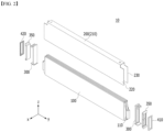
- FIG. 2 is an exploded perspective view which schematically shows a cell unit including a configuration of battery cells and a cell cover accommodated inside a battery pack according to an embodiment of the present invention.
- FIG. 3 is a perspective view showing a state in which the components of FIG. 2 are combined.
- the battery pack 1000 includes a battery cell 100, a cell cover 200, and a pack case 600.
- the battery cell 100 may be a pouch-type battery cell. That is, the battery cell 100 is a pouch-type secondary battery, and may include an electrode assembly, an electrolyte, and a pouch exterior material.
- the pouch-type battery cell 100 may be manufactured through a process of injecting an electrolyte into a cell case in a state where the electrode assembly is accommodated in the cell case, and sealing the cell case.
- the cell case may be sealed by bonding both ends of the battery cell 100 and one side part connecting them.
- a plurality of such battery cells 100 may be included in a battery pack. And, the plurality of battery cells 100 may be stacked in at least one direction. For example, referring to FIG. 1 , the plurality of battery cells 100 may be stacked and disposed in a horizontal direction, for example, in a left-right direction (x-axis direction in the figure). Further, the plurality of battery cells 100 may also be disposed in a front-back direction (y-axis direction in the figure) as shown in FIG. 1 .
- the plurality of battery cells 100 may be disposed so as to form a plurality of rows in the left-right direction and the horizontal direction while being disposed in the horizontal direction.
- the plurality of battery cells 100 may be stacked in such a manner that two rows of cells disposed in the left-right direction are provided in the front-back direction.
- the battery pack according to the present invention can employ various types of battery cells 100 known at the time of filing the present application, and therefore, detailed description of the configuration or the like of such battery cells 100 will be omitted.
- the pack case 600 has an empty space formed therein and can accommodate a plurality of battery cells 100.
- the pack case 600 may comprise an upper case 610 and a lower case 620 as shown in FIG. 1 .
- the lower case 620 is configured in a box shape having an open upper end and can accommodate a plurality of battery cells in the inner space.
- the upper case 610 may be configured in a lid shape that covers the open upper end of the lower case 620. At this time, the upper case 610 may be configured in a box shape having an open lower end.
- the cell cover 200 may also be accommodated in the inner space of the pack case 600 together with the plurality of battery cells 100.
- the pack case 600 may be formed of a plastic or metal material. Further, the pack case 600 may employ exterior materials of various battery packs known at the time of filing of the present application.
- the cell cover 200 may be configured to surround battery cells 100 in the inner space of a pack case. That is, the cell cover 200 may be configured to surround at least a part of the battery cells among the plurality of battery cells 100 included in the battery pack. Moreover, the cell cover may be provided to at least partially surround the battery cell 100.
- the cell cover 200 may be configured to support the stacked state of the plurality of battery cells 100 inside the pack case 600 through a structure surrounding the battery cells. For example, as shown in FIG. 1 , a plurality of battery cells 100 may be stacked in a horizontal direction (x-axis direction in the drawing). At this time, the cell cover 200 may be configured to stably maintain the stacked state of the plurality of battery cells 100 stacked in the horizontal direction in this way.
- a plurality of battery cells 100 can be directly seated and accommodated inside the pack case 600 without a module case.
- the exterior material is made of a soft material, so that it may be vulnerable to external impact and low in hardness. Therefore, it is not easy to accommodate only the battery cells 100 themselves inside the pack case 600 without accommodating them in the module case.
- the plurality of battery cells 100 are coupled with the cell cover 200 while being at least partially surrounded by the cell cover 200, and are directly accommodated in the pack case 600, and the stacked state can be stably maintained.
- the battery pack 1000 does not need to be further provided with a module case, a stacking frame, or a fastening member such as a bolt for maintaining the stacked state of cells. Therefore, a space occupied by other components such as a module case or a stacking frame or a space for securing tolerance due thereto can be eliminated. Therefore, since the battery cells can occupy more space as much as the eliminated space, the energy density of the battery pack can be further improved.
- the volume or weight of the battery pack can be reduced, and the manufacturing process can be simplified.
- handling of the battery cell 100 can be made easier.
- the battery cells 100 may be held by a jig or the like.
- the jig may hold the cell cover 200 surrounding the battery cell 100 without directly holding the battery cell 100. Therefore, it is possible to prevent the battery cell 100 from being damaged or damaged by the jig.
- the cell cover 200 is coupled to the battery cell 100, thereby capable of effectively protecting the battery cell 100 without a module case.
- the cell cover 200 may be composed of various materials to secure rigidity.
- the cell cover 200 may be composed of a metal material.
- the stacked state of the battery cells can be more stably maintained, and the battery cells can be more safely protected from external impact.
- the cell cover 200 may comprise a steel material, more specifically a stainless steel (SUS) material.
- the cell cover 200 may be entirely made of SUS material.
- the cell cover 200 When the cell cover 200 is made of a steel material in this way, it has excellent mechanical strength and rigidity, so that the stacked state of the battery cells 100 can be more stably supported. Further, in this case, it is possible to more effectively prevent the battery cell 100 from being damaged or broken by an external impact such as an acicular body. Moreover, in this case, the handling of the battery cell can be made easier.
- the cell cover 200 is made of a steel material as in the above embodiment, the overall structure can be stably maintained due to its high melting point when flames generate from the battery cells 100.
- the steel material has a higher melting point than an aluminum material, it does not melt even by the flames ejected from the battery cell 100, and can stably maintain its shape. Therefore, it is possible to excellently secure flame propagation prevention or delay effects between battery cells 100, venting control effects, and the like.
- the cell cover 200 may be configured to accommodate one or more battery cells 100.
- one cell cover 200 may be configured to surround one battery cell 100 or a plurality of battery cells 100.
- the cell cover 200 is individually coupled for each battery cell 100 among the plurality of battery cells 100, or the cell cover 200 may be configured to surround two or more battery cells 100 together.
- the cell cover 200 may be at least partially adhered to the outer surface of the battery cell 100.
- the inner surface of the cell cover 200 may be adhered to the accommodating portion of the battery cell 100.
- One or more cell covers 200 may be included in the battery pack.
- the cell cover 200 may be configured so that the plurality of battery cells 100 included in a battery pack are grouped into a unit.
- one cell cover 200 may constitute one cell unit 10.
- one cell unit 10 may include one or more battery cells 100.
- the battery pack may include a large number of cell units, and in this case, a large number of cell covers 200 may be included in the battery pack.
- the battery pack may include the same number of cell covers 200 as the number of battery cells 100.
- the battery pack may include a smaller number of cell covers 200 than the number of battery cells 100.
- the cell cover 200 may be configured to support the plurality of battery cells 100 in an upright state. As shown in FIG. 2 , each battery cell 100 has two wide surfaces, and corner portions of the wide surfaces may have a sealing portion or a folded portion of the pouch exterior material. Therefore, it is generally difficult to stack the battery cells 100 in a shape of being erected in a vertical direction. However, in the battery pack according to the present invention, the cell cover 200 may be configured to surround one or more battery cells 100 and support the surrounded battery cells 100 in an erected state, that is, an upright state.
- the cell cover 200 may be configured such that a large number of battery cells 100 can be stacked in a horizontal direction in a state of being erected in the up and down direction.
- a large number of cell covers 200 are stacked with each other in a horizontal direction, and each cell cover 200 may be configured to surround one or more battery cells 100.
- the cell cover 200 makes it possible to stably maintain the configuration in which a large number of battery cells 100 are stacked side by side in a horizontal direction in a state in which each is erected.
- the cell cover 200 may be configured to be self-supportable in the inner space of the pack case 600. That is, the cell cover 200 may be configured to maintain an upright state by itself without the aid of other components provided in the battery pack, such as the pack case 600 or the battery cell 100.
- the cell cover 200 may be directly seated on the bottom surface of the lower case 620.
- a part of the cell cover 200 and a lower end of the cell cover 200 may be seated in direct contact with the bottom surface of the lower case 620.
- a thermal resin layer 626 may be formed on the bottom surface of the lower case 620.
- the thermal resin layer 626 may transfer heat to a heat sink so that heat generated in the battery cell 100 is dissipated through a heat sink (not shown).
- a heat sink may be formed under the thermal resin layer 626.
- the heat sink is formed on the bottom surface of the lower case 620, and a thermal resin layer 626 may be applied to the upper surface of the heat sink. Since the thermal resin layer 626 has adhesive properties, the cell cover 200 and/or the battery cell 100 may be coupled to the bottom surface of the lower case 620 or the heat sink. The thermal resin layer 626 can more stably maintain the upright state of the battery cell 100 and the cell cover 200.
- the cell cover 200 may be configured to stably maintain the seated state when the lower end is seated in this way.
- the cell cover 200 is composed of a metal material having excellent rigidity such as steel, especially a SUS material, the self-supporting state can be maintained more stably. Therefore, in this case, the upright state of the battery cell 100 can be supported more reliably.
- the cell cover 200 may be configured to partially surround the battery cell so that at least one side of the surrounded battery cell is exposed to the outside. That is, the cell cover 200 may be configured to surround only a part of the battery cell 100 without completely surrounding the battery cell 100 as a whole. In particular, the cell cover 200 may be configured such that at least one side of the battery cell is exposed toward the pack case.
- the cell cover 200 is configured to surround one battery cell 100, but the surrounded battery cell 100, that is, the lower portion of the battery cell 100 accommodated in the inner space may not be surrounded by the cell cover 200. Therefore, the lower portion of the battery cell 100 is exposed toward the pack case 600 and may directly face the pack case 600. In particular, referring to the embodiment shown in FIG. 1 , the lower portion of the battery cell 100 may be exposed toward the bottom surface of the lower case 620.
- the cooling performance of the battery pack can be secured more effectively.
- the battery cell 100 and the pack case 600 may be brought into direct face-to-face contact. Therefore, heat emitted from each battery cell 100 is directly transferred to the pack case 600, thereby capable of improving the cooling performance.
- efficient cooling performance can be realized.
- a space for flowing a coolant such as air between the battery cells 100 may not be provided.
- a thermal interface material may be interposed between mutually different components in order to increase heat transfer performance.
- the TIM may be filled between the battery cell 100 and the cell cover 200, between the cell cover 200 and the pack case 600, and/or between the battery cell 100 and the pack case 600.
- the cooling performance of the battery pack such as dual cooling performance, can be further improved.
- the cell cover 200 may be configured to surround an edge portion that is not provided with an electrode lead among various edge portions of the battery cell 100 accommodated therein.
- the battery cell 100 may comprise two electrode leads 110, that is, a cathode lead and an anode lead. At this time, the two electrode leads may be respectively positioned at the front side edge portion and the rear side edge portion. At this time, the cell cover may be configured to surround one of the remaining two edge portions excluding the front side edge portion and the rear side edge portion.
- the battery cell 100 may be formed in a substantially hexahedral shape.
- the electrode leads 110 that is, an anode lead and a cathode lead may be respectively formed on two of the six surfaces.
- the cell cover 200 is provided to cover at least a part of three of the remaining four surfaces of the six-sided battery cell 100 excluding the two surfaces on which the electrode leads 110 are formed.
- the embodiment of the present invention it is possible to guide the discharge direction of the flame or the like to the exposed side surface of the cell cover 200.
- a flame or the like can be discharged in such an opened direction.
- the cell cover 200 is configured such that the front direction and the rear direction are open as described above, side directional venting can be easily realized.
- a configuration for supporting and protecting one or more battery cells can be easily realized as one cell cover 200.
- the lower side edge portion may be in direct face-to-face contact with the pack case 600 without being surrounded by the cell cover 200. Therefore, the heat of the battery cells 100 surrounded by the cell cover 200 can be quickly and smoothly discharged to the lower pack case 600 side. Thus, the cooling performance of the battery pack can be more effectively secured.
- such a configuration can be more effectively implemented when cooling is mainly performed in the lower portion of the pack case 600.
- cooling may be mainly performed in the lower portion of the pack case 600.
- the lower edge portion of each battery cell 100 is in face-to-face contact with the pack case as in the above embodiment, heat is quickly transferred from each battery cell 100 to the pack case side, so that the cooling performance can be further improved.
- the cell cover 200 may be formed in a shape similar to the letter n. And, the cell cover 200 may be configured to cover other portions of the battery cell 100 accommodated therein, except for the front side and the rear side where the electrode lead protrudes through such a shape, and the lower side. That is, the cell cover 200 may be provided to cover the outer side and the upper side of the accommodating portion of the battery cell accommodated therein.
- the cell cover 200 may include an upper side cover portion 210, a first side cover portion 220 , and a second side cover portion 230 as shown in FIG. 2 .
- the upper side cover portion 210 may be configured to surround the upper portion of the battery cell 100 accommodated therein.
- the upper side cover portion 210 may be configured to contact with or be spaced apart from the upper side edge portion of the battery cell 100.
- the upper side cover portion 210 may be configured in a planar shape.
- the upper side cover portion 210 may have a cross section formed in a straight line shape in a horizontal direction, and may surround the upper side edge portion of the battery cell 100 in a straight line shape from the outside.
- the first side cover portion 220 may be configured to extend downward from one end of the upper side cover portion 210.
- the first side cover portion 220 may be configured to extend downward (-Z axis direction in the figure) at the left side end of the upper side cover portion 210.
- the first side cover portion 220 may be formed in a planar shape. At this time, the first side cover portion 220 may be configured in a bent shape at the upper side cover portion 210.
- first side cover portion 220 may be configured to cover the outer side of one side accommodating portion of the battery cell 100 accommodated therein.
- the first side cover portion 220 may be configured to cover the left side surface of the accommodating portion of the accommodated battery cell 100 from the left side.
- the first side cover portion 220 may directly contact the outer side surface of the accommodating portion.
- the second side cover portion 230 may be positioned to be spaced apart from the first side cover portion 220 in a horizontal direction. Further, the second side cover portion 230 may be configured to extend downward from the other end of the upper side cover portion 210. For example, the second side cover portion 230 may be configured to extend long in a downward direction at the right end of the upper side cover portion 210. Moreover, the second side cover portion 230 may also be configured in a planar shape like the first side cover portion 220. At this time, the second side cover portion 230 and the first side cover portion 220 may be disposed parallel to each other while being spaced apart in a horizontal direction.
- the second side cover portion 230 may be configured to surround the outer side of the other side accommodating portion of the battery cell 100 accommodated therein.
- the second side cover portion 230 may be configured to surround the right side surface of the accommodating portion of the accommodated battery cell 100 from the right side.
- the second side cover portion 230 may directly contact the outer side surface of the accommodating portion.
- the inner space may be defined by the upper side cover portion 210, the first side cover portion 220 and the second side cover portion 230. Further, the cell cover 200 may accommodate one or more battery cells in the inner space defined in this way.
- lower side ends of the first side cover portion 220 and the second side cover portion 230 may contact the bottom surface of the pack case 600.
- the contact configuration between the lower side ends of the first side cover portion 220 and the second side cover portion 230 and the pack case 600 may be configured to extend long in the front-back direction (y-axis direction in the figure). According to such an embodiment, the self-supporting configuration of the cell cover 200 that can maintain the battery cell 100 accommodated therein in an upright state can be realized more stably.
- first side cover portion 220 and the second side cover portion 230 may have the same height as each other. That is, the first side cover portion 220 and the second side cover portion 230 may have the same length extending downward from the upper side cover portion 210. In this case, the self-supporting configuration of the cell cover 200 can be more easily realized.
- the upper side cover portion 210 may face the upper side edge portion of the battery cell 100 and may surround the upper side edge portion together with the first side cover portion 220 and the second side cover portion 230.
- the cross-sectional area of the first side cover portion 220 and the second side cover portion 230 is formed larger than the cross-sectional area of the battery cell 100 which the first side cover portion 220 and the second side cover portion 230 face, thereby being able to prevent the accommodating portion from being exposed to the outside and secure the safety to a maximum.
- the battery cell 100 may include a sealing portion 240 (see FIG. 4 ).
- the sealing portion 240 may be a portion formed by sealing one side portion of the battery cell 100 facing the cell cover 200.
- the sealing portion 240 may be sealed by a method such as heat sealing, and may be bent one or more times to improve sealing performance.
- the sealing portion 240 may be a double side folded portion.
- the upper side edge portion is a sealing portion 240 (see FIG. 4 ) of the battery cell 100 and may be a double side folded portion.
- the lower side edge portion may be an unsealed portion of the battery cell 100.
- the cell cover 200 may be configured to surround the battery cell 100, wherein at least a part of the sealed portion is surrounded, and at least a part of the unsealed portion is not surrounded, and exposed to the outside.
- the cell cover 200 may be configured to cover an upper side edge portion which is a part of the sealing portion of the battery cell 100.
- the battery cell 100 accommodated inside the cell cover 200 may be configured such that the upper side edge portion, which is a sealing portion, faces the upper side cover portion 210.
- the cell cover 200 may surround the battery cell 100 so that the lower side edge portion, which is the unsealed portion of the battery cell 100 is exposed to the outside.
- the lower side edge portion which is an unsealed portion of the battery cell 100 may be disposed on the open surface of the cell cover 200.
- the upper side edge portion as a sealing portion may be more vulnerable to discharge of relatively high-temperature gas or flame than the lower side edge portion, which is an unsealed portion.
- the upper side edge portion, which is a sealing portion is arranged so as to face the upper side cover portion 210, which may be more advantageous for directional venting.
- the lower side edge portion as the unsealed portion has a relatively larger cross-sectional area than the upper side edge as the sealing portion, is provided in a flat shape, and may be disposed on the open surface of the cell cover 200 and directly contact the thermal resin layer 626 of FIG. 1 to thereby increase cooling efficiency.
- the first side cover portion 220 and the second side cover portion 230 may extend from the upper side cover portion 210 toward one surface of the vehicle body, and the upper side edge portion may be disposed farther from one surface of the vehicle body than the lower side edge portion. That is, when the lower case 620 is seated on one surface of the vehicle body, the cell cover 200 may be configured such that a surface disposed relatively close to one surface of the vehicle body is opened.
- the first side cover portion 220 and the second side cover portion 230 may extend away from the one surface of the vehicle body at the upper side cover portion 210, and the upper side edge portion may be disposed closer to one side of the vehicle body than the lower side edge portion. That is, when the upper case 610 is seated on one surface of the vehicle body, the cell cover 200 may be configured such that a surface disposed relatively far from one surface of the vehicle body is opened.
- the arrangement of the cell cover 200 and the battery cell 100 can be set variously according to the relationship between the vehicle body, the pack case 600, and the configuration disposed on the vehicle body other than the pack case 600.
- the cell cover 200 having an n-shaped configuration has been mainly shown and described, but the cell cover 200 can be configured in various other shapes.
- the cell cover 200 may be formed in various other shapes such as an I-shape, a U-shape, and an L-shape.
- FIG. 4 is an exploded perspective view which schematically shows a partial configuration of a battery pack according to an embodiment of the present invention.
- the battery pack according to the present invention may further include a busbar assembly 300.
- the busbar assembly 300 may be configured to electrically connect the plurality of battery cells 100 to each other.
- the busbar assembly 300 may be coupled to the electrode leads 110 of the plurality of battery cells 100 to electrically connects between the plurality of battery cells 100 in series and/or in parallel.
- the busbar assembly 300 may comprise a busbar terminal that is composed of an electrically conductive material such as copper or aluminum and is in direct contact with the electrode lead 110, and a busbar housing that is made of an electrically insulating material such as plastic and supports the busbar terminal.
- the busbar assembly 300 may also be included on both sides where the electrode lead 110 is provided.
- the busbar assembly 300 may also be located on both the front side and the rear side.
- the busbar assembly 300 may be coupled with one or more cell covers 200. At this time, the busbar assembly 300 may be coupled to an end of one cell cover 200. At this time, one or a plurality of battery cells 100 may be accommodated in one cell cover 200.
- the busbar assembly 300 may be coupled with the cell cover 200 in various ways.
- the busbar assembly 300 may be coupled and fixed to the cell cover 200 through various fastening methods such as adhesion, welding, fitting, hooking, bolting, and riveting.
- the battery pack 1000 may further include an insulating cover portion 350 and an end plate 400.
- the insulating cover portion 350 is made of an electrical insulating material, prevents the busbar assembly 300 from being exposed to the outside by the end plate 400, and can secure and maintain electrical insulation.
- the end plate 400 covers the front and rear surfaces of the plurality of battery cells 100 and may be coupled with the cell cover 200.
- the end plate 400 may include a first end plate 410 disposed on the front side of the battery cell 100 (y-axis direction of the figure), and a second end plate 420 disposed on the rear side of the battery cell 100 (in the -y axis direction in the figure).
- the end plate 400 may be sealed and coupled to the cell cover 200 via welding.
- the end plate 400 may secure structural stability of the cell unit 10 by fixing the busbar assembly 300 and the insulating cover portion 350. Meanwhile, the end plate 400 may be formed with a hole through which the insulating cover portion 350 is exposed, and in some cases, directional venting may be induced through the hole.
- venting passage and the adhesive layer included in the battery pack 1000 according to the present embodiment will be described in more detail.
- FIG. 4 is a perspective view taken along the cut plane A of FIG. 3 .
- FIG. 5 is a front view of FIG. 4 .
- an air gap may exist between the upper portion of the cell cover 200 and the battery cell 100.
- a venting passage VP (see FIG. 7 ) is formed through the air gap so that gas generated in the battery cell 100 can move.
- the upper side edge portion of the battery cell 100 is formed with the sealing portion 240, relatively high-temperature gas or flame can be more easily discharged than the lower edge portion, which is an unsealed portion.
- gas or flame When gas or flame generates, it can be released as high-temperature gas and spark through the venting passage VP (see FIG. 7 ), and sparks come into contact with external oxygen, or the like to cause ignition.
- the battery pack of the present embodiment may include an adhesive layer 250 to prevent sparks, i.e., high-temperature particles from scattering to the outside, in order to solve the above-mentioned problems.
- the adhesive layer 250 may be disposed on the inner surface of the space between the cell cover 200 and the battery cell 100. Specifically, the adhesive layer 250 may be disposed on the inner surface of the upper side cover portion 210. Further, the adhesive layer 250 may be further disposed on at least a part of the inner surface of the first side cover portion 220 and at least a part of the inner surface of the second side cover portion 230.
- the adhesive layer 250 may be disposed on an inner surface of the upper side cover portion 210, an inner surface of a part of the first side cover portion 220 extending downward from one end of the upper side cover portion 210, and an inner surface of a part of the second side cover portion 230 extending downward from the other end of the upper side cover portion 210.
- a relatively large adhesive layer is formed between the sealing portion 240 and the upper side cover portion 210, it is possible to catch more sparks.
- the adhesive layer 250 When the adhesive layer 250 is formed on the cell unit 10, particles that move along the air gap, which is the venting passage when the battery cell 100 ignites, can adhere to the adhesive layer 250, thereby capable of preventing particles from scattering to the outside of the cell unit.
- the emission of high-temperature particles, i.e., sparks is restricted by the adhesive layer 250, the possibility of the sparks coming into contact with external oxygen is reduced, and thus additional thermal runaway phenomena can be prevented.
- the adhesive layer 250 may be attached in layered shape to the inside of the vending passage, or may be applied in a liquid form and then formed as a layer.
- the adhesive layer 250 may include an adhesive material.
- the adhesive material that can be used for the adhesive layer 250 can be used irrespective of the type as long as they have adhesive properties that enables particles to adhere thereto.
- Examples of the adhesive material include those containing acrylates or silicones, and in the adhesive material, ester rubber, phenol resin, or other materials may be used as auxiliaries, or low-molecular materials such as castor oil or polyisobutylene may be further mixed.
- the adhesive layer 250 may be provided on the venting passage.
- the venting passage may extend along the y-axis direction shown in FIGS. 2 and 3 .
- FIG. 6 is a view showing a state of a cell unit in which an ignition phenomenon has occurred according to a comparative example.
- FIG. 7 is a view showing a state in which venting gas is discharged in the y-axis direction of FIG. 3 .
- the cell unit may include a venting passage formed between the cell cover 21 and the battery cell 1.
- the battery cell 1 may generate a large amount of heat during charging and discharging process, and if the temperature is higher than the proper temperature due to reasons such as overcharging, the performance may deteriorate. Excessive temperature rise may cause explosion or ignition.
- the internal material of the cell may be ejected along with high-temperature inflammable gas to the outside.
- Such internal materials are mainly materials such as C, Cu, Al, Ni, Co, Mg, and Li, and are ejected in the form of high-temperature particles, i.e., sparks.
- the cell unit 10 may include a venting passage VP formed between the battery cell 100 and the upper side cover portion 210.
- the venting passage VP may be for discharging gas generated from the battery cell 100 to the outside of the cell cover 200.
- the venting passage VP may be formed in a separation space between the cell cover 200 and the battery cell 100.
- a venting part for discharging internal gas of the battery cell 100 for example, a hole of the end plate 400 described in FIGS. 2 and 3 may be located at one end of the venting passage VP. Flames, gases, and the like discharged from each battery cell 100 to the venting passage VP may move along the venting passage VP and be discharged to the outside through an outlet (not shown) provided in the cell unit 10.
- particles moving along the venting passage VP may be attached to the adhesive layer 250, and thus particles may be prevented from scattering to the outside of the cell unit 10.
- the emission of high-temperature particles, i.e., sparks is restricted by the adhesive layer 250, the possibility of the spark coming into contact with external oxygen is lowered, and thus additional thermal runaway phenomena can be prevented.
- FIG. 8 is a diagram showing a cell unit according to another embodiment of the present invention.
- the embodiment of FIG. 8 is a modification of the embodiment of FIG. 5 , and the cell unit 20 according to the present embodiment may further include a heat transfer member 260 covering an upper portion of the battery cell 100.
- the heat transfer member 260 may be coated and formed with a silicon-based material or formed as a thermally conductive pad.
- the adhesive layer 250 may be formed between the heat transfer member 260 and the upper side cover portion 210.
- the adhesive layer 250 may be formed on an inner surface of the upper side cover portion 210, an inner surface of a part of the first side cover portion 220 extending downward from one end of the upper side cover portion 210 to the heat transfer member 260, and an inner surface of a part of the second side cover portion 230 extending downward from the other end of the upper side cover portion 210 to the heat transfer member 260.
- the formation position of the adhesive layer 250 is not limited thereto, and may be directly applied or attached to the upper surface of the heat transfer member 260.
- the battery pack according to an embodiment of the present invention may further include a battery management system (BMS) and/or a cooling device that control and manage battery's temperature, voltage, etc.
- BMS battery management system
- a cooling device that control and manage battery's temperature, voltage, etc.
- the battery pack according to an embodiment of the present invention can be applied to various devices.
- a device to which a battery pack is applied may be vehicle means such as an electric bike, an electric vehicle, and a hybrid electric vehicle.
- vehicle means such as an electric bike, an electric vehicle, and a hybrid electric vehicle.
- the above-mentioned device is not limited thereto, and the battery pack according to the present embodiment can be used in various devices other than the above-mentioned examples, which also falls under the scope of the present invention.
Landscapes
- Chemical & Material Sciences (AREA)
- Chemical Kinetics & Catalysis (AREA)
- Electrochemistry (AREA)
- General Chemical & Material Sciences (AREA)
- Engineering & Computer Science (AREA)
- Inorganic Chemistry (AREA)
- Materials Engineering (AREA)
- Manufacturing & Machinery (AREA)
- Battery Mounting, Suspending (AREA)
- Sealing Battery Cases Or Jackets (AREA)
- Gas Exhaust Devices For Batteries (AREA)
- Secondary Cells (AREA)
Applications Claiming Priority (3)
| Application Number | Priority Date | Filing Date | Title |
|---|---|---|---|
| KR20220089844 | 2022-07-20 | ||
| KR1020230076240A KR20240012295A (ko) | 2022-07-20 | 2023-06-14 | 전지 팩 및 이를 포함하는 디바이스 |
| PCT/KR2023/009963 WO2024019414A1 (fr) | 2022-07-20 | 2023-07-12 | Bloc-batterie et dispositif le comprenant |
Publications (2)
| Publication Number | Publication Date |
|---|---|
| EP4425677A1 true EP4425677A1 (fr) | 2024-09-04 |
| EP4425677A4 EP4425677A4 (fr) | 2025-07-16 |
Family
ID=89618047
Family Applications (1)
| Application Number | Title | Priority Date | Filing Date |
|---|---|---|---|
| EP23843264.5A Pending EP4425677A4 (fr) | 2022-07-20 | 2023-07-12 | Bloc-batterie et dispositif le comprenant |
Country Status (4)
| Country | Link |
|---|---|
| US (1) | US20250030116A1 (fr) |
| EP (1) | EP4425677A4 (fr) |
| JP (1) | JP7852985B2 (fr) |
| WO (1) | WO2024019414A1 (fr) |
Family Cites Families (14)
| Publication number | Priority date | Publication date | Assignee | Title |
|---|---|---|---|---|
| JP2001060453A (ja) | 1999-08-20 | 2001-03-06 | Sharp Corp | 電 池 |
| EP1744383B1 (fr) | 2004-03-31 | 2014-05-07 | NEC Corporation | Dispositif electrique avec revetement de film et element d'armature |
| JP5378670B2 (ja) | 2006-10-13 | 2013-12-25 | パナソニック株式会社 | 電池パック |
| WO2015119307A1 (fr) * | 2014-02-04 | 2015-08-13 | 주식회사 코캄 | Module d'accumulateurs au lithium et bloc-batterie d'accumulateurs au lithium à sécurité améliorée |
| KR102005488B1 (ko) * | 2015-06-16 | 2019-10-01 | 주식회사 엘지화학 | 이차 전지용 셀 커버 및 이를 포함하는 배터리 모듈 |
| JP6601235B2 (ja) | 2016-01-26 | 2019-11-06 | 株式会社デンソー | 電池パック |
| KR102067710B1 (ko) * | 2016-07-06 | 2020-01-17 | 주식회사 엘지화학 | 배터리 모듈 및 이를 포함하는 배터리 팩, 자동차 |
| SG11202110988XA (en) * | 2019-04-01 | 2021-10-28 | Spear Power Systems Inc | Apparatus for mitigation of thermal event propagation for battery systems |
| CN112467285A (zh) * | 2020-12-14 | 2021-03-09 | 天津市捷威动力工业有限公司 | 延缓热失控的电池模组及使用其的车辆 |
| KR102940430B1 (ko) * | 2021-01-11 | 2026-03-16 | 주식회사 엘지에너지솔루션 | 화재 발생 및 폭발을 방지할 수 있는 구조를 갖는 배터리 모듈, 그리고 이를 포함하는 배터리 팩 및 자동차 |
| KR102857913B1 (ko) * | 2021-06-17 | 2025-09-09 | 주식회사 엘지에너지솔루션 | 개선된 벤팅 성능을 갖는 배터리 모듈 |
| CN116745984A (zh) * | 2021-07-09 | 2023-09-12 | 株式会社Lg新能源 | 具有增强安全性的电池模块和电池组 |
| KR20230070861A (ko) * | 2021-11-15 | 2023-05-23 | 주식회사 엘지에너지솔루션 | 전지 팩 및 이를 포함하는 디바이스 |
| WO2024048985A1 (fr) * | 2022-08-31 | 2024-03-07 | 주식회사 엘지에너지솔루션 | Bloc-batterie, module de batterie et véhicule les comprenant |
-
2023
- 2023-07-12 WO PCT/KR2023/009963 patent/WO2024019414A1/fr not_active Ceased
- 2023-07-12 JP JP2024522537A patent/JP7852985B2/ja active Active
- 2023-07-12 US US18/714,436 patent/US20250030116A1/en active Pending
- 2023-07-12 EP EP23843264.5A patent/EP4425677A4/fr active Pending
Also Published As
| Publication number | Publication date |
|---|---|
| US20250030116A1 (en) | 2025-01-23 |
| WO2024019414A1 (fr) | 2024-01-25 |
| JP2024539654A (ja) | 2024-10-29 |
| EP4425677A4 (fr) | 2025-07-16 |
| JP7852985B2 (ja) | 2026-04-28 |
Similar Documents
| Publication | Publication Date | Title |
|---|---|---|
| EP3926733A1 (fr) | Bloc-batterie et dispositif le comprenant | |
| US20240322356A1 (en) | Battery module and battery pack including the same | |
| US20240421420A1 (en) | Battery Pack and Device Including the Same | |
| US20250253484A1 (en) | Battery Pack, Battery Module, and Vehicle Including the Same | |
| EP4210154A1 (fr) | Bloc-batterie et dispositif le comprenant | |
| KR102622859B1 (ko) | 배터리 모듈, 배터리 팩 및 이를 포함하는 자동차 | |
| EP4170793B1 (fr) | Module de batterie et bloc-batterie le comprenant | |
| US20260005351A1 (en) | Battery Pack and Device Including the Same | |
| US20250055122A1 (en) | Battery pack | |
| EP4425677A1 (fr) | Bloc-batterie et dispositif le comprenant | |
| EP4261985A1 (fr) | Bloc-batterie et dispositif le comprenant | |
| KR20230146306A (ko) | 배터리 팩 및 이를 포함하는 자동차 | |
| KR20230040125A (ko) | 전지 모듈 및 이를 포함하는 전지 팩 | |
| CN223884513U (zh) | 电池组和包括该电池组的装置 | |
| CN118235288A (zh) | 电池组和包括该电池组的装置 | |
| EP4525175A1 (fr) | Bloc-batterie et module de batterie | |
| KR20240012295A (ko) | 전지 팩 및 이를 포함하는 디바이스 | |
| EP4199230A1 (fr) | Dispositif coupe-feu et bloc-batterie le comprenant | |
| EP4546511A1 (fr) | Élément de refroidissement et batterie le comprenant | |
| US20250364656A1 (en) | Battery module and battery pack including the same | |
| EP4175020A1 (fr) | Module de batterie et bloc-batterie le comprenant | |
| EP4712246A1 (fr) | Bloc-batterie et dispositif le comprenant | |
| US20240136641A1 (en) | Battery pack and device including the same | |
| KR20240012299A (ko) | 배터리 팩 및 이를 포함하는 디바이스 | |
| KR20240012312A (ko) | 전지 팩 및 이를 포함하는 디바이스 |
Legal Events
| Date | Code | Title | Description |
|---|---|---|---|
| STAA | Information on the status of an ep patent application or granted ep patent |
Free format text: STATUS: THE INTERNATIONAL PUBLICATION HAS BEEN MADE |
|
| PUAI | Public reference made under article 153(3) epc to a published international application that has entered the european phase |
Free format text: ORIGINAL CODE: 0009012 |
|
| STAA | Information on the status of an ep patent application or granted ep patent |
Free format text: STATUS: REQUEST FOR EXAMINATION WAS MADE |
|
| 17P | Request for examination filed |
Effective date: 20240527 |
|
| AK | Designated contracting states |
Kind code of ref document: A1 Designated state(s): AL AT BE BG CH CY CZ DE DK EE ES FI FR GB GR HR HU IE IS IT LI LT LU LV MC ME MK MT NL NO PL PT RO RS SE SI SK SM TR |
|
| A4 | Supplementary search report drawn up and despatched |
Effective date: 20250617 |
|
| RIC1 | Information provided on ipc code assigned before grant |
Ipc: H01M 50/383 20210101AFI20250611BHEP Ipc: H01M 50/184 20210101ALI20250611BHEP Ipc: H01M 50/211 20210101ALI20250611BHEP Ipc: H01M 50/249 20210101ALI20250611BHEP Ipc: H01M 50/251 20210101ALI20250611BHEP Ipc: H01M 50/342 20210101ALI20250611BHEP Ipc: H01M 10/0525 20100101ALI20250611BHEP |
|
| DAV | Request for validation of the european patent (deleted) | ||
| DAX | Request for extension of the european patent (deleted) |