EP4425721A1 - Fiche pour un connecteur sous-marin et méthode de changement de connexion sous-marine entre une fiche et un réceptacle - Google Patents
Fiche pour un connecteur sous-marin et méthode de changement de connexion sous-marine entre une fiche et un réceptacle Download PDFInfo
- Publication number
- EP4425721A1 EP4425721A1 EP24160765.4A EP24160765A EP4425721A1 EP 4425721 A1 EP4425721 A1 EP 4425721A1 EP 24160765 A EP24160765 A EP 24160765A EP 4425721 A1 EP4425721 A1 EP 4425721A1
- Authority
- EP
- European Patent Office
- Prior art keywords
- contact
- disk
- plug
- conducting region
- aperture
- Prior art date
- Legal status (The legal status is an assumption and is not a legal conclusion. Google has not performed a legal analysis and makes no representation as to the accuracy of the status listed.)
- Pending
Links
- 238000000034 method Methods 0.000 title claims description 34
- 239000004020 conductor Substances 0.000 claims description 28
- 239000012777 electrically insulating material Substances 0.000 claims description 4
- 238000010276 construction Methods 0.000 description 14
- 230000033001 locomotion Effects 0.000 description 8
- 238000005260 corrosion Methods 0.000 description 4
- 230000007797 corrosion Effects 0.000 description 4
- 230000007246 mechanism Effects 0.000 description 4
- 239000000853 adhesive Substances 0.000 description 3
- 230000001070 adhesive effect Effects 0.000 description 3
- 238000009434 installation Methods 0.000 description 3
- 238000004519 manufacturing process Methods 0.000 description 3
- 238000005219 brazing Methods 0.000 description 2
- 238000005553 drilling Methods 0.000 description 2
- 239000012530 fluid Substances 0.000 description 2
- 210000004907 gland Anatomy 0.000 description 2
- 239000000463 material Substances 0.000 description 2
- 230000013011 mating Effects 0.000 description 2
- 238000012360 testing method Methods 0.000 description 2
- 230000007704 transition Effects 0.000 description 2
- 238000013519 translation Methods 0.000 description 2
- XLYOFNOQVPJJNP-UHFFFAOYSA-N water Substances O XLYOFNOQVPJJNP-UHFFFAOYSA-N 0.000 description 2
- 238000003466 welding Methods 0.000 description 2
- 241000191291 Abies alba Species 0.000 description 1
- 239000004593 Epoxy Substances 0.000 description 1
- 230000005540 biological transmission Effects 0.000 description 1
- 238000004891 communication Methods 0.000 description 1
- 230000002950 deficient Effects 0.000 description 1
- 238000002405 diagnostic procedure Methods 0.000 description 1
- 238000010292 electrical insulation Methods 0.000 description 1
- 238000005516 engineering process Methods 0.000 description 1
- 238000007667 floating Methods 0.000 description 1
- 230000036541 health Effects 0.000 description 1
- 238000010438 heat treatment Methods 0.000 description 1
- 229930195733 hydrocarbon Natural products 0.000 description 1
- 150000002430 hydrocarbons Chemical class 0.000 description 1
- 238000011065 in-situ storage Methods 0.000 description 1
- 239000007788 liquid Substances 0.000 description 1
- 238000006467 substitution reaction Methods 0.000 description 1
- 238000012546 transfer Methods 0.000 description 1
Images




Classifications
-
- H—ELECTRICITY
- H01—ELECTRIC ELEMENTS
- H01R—ELECTRICALLY-CONDUCTIVE CONNECTIONS; STRUCTURAL ASSOCIATIONS OF A PLURALITY OF MUTUALLY-INSULATED ELECTRICAL CONNECTING ELEMENTS; COUPLING DEVICES; CURRENT COLLECTORS
- H01R33/00—Coupling devices specially adapted for supporting apparatus and having one part acting as a holder providing support and electrical connection via a counterpart which is structurally associated with the apparatus, e.g. lamp holders; Separate parts thereof
- H01R33/965—Dustproof, splashproof, drip-proof, waterproof, or flameproof holders
-
- H—ELECTRICITY
- H01—ELECTRIC ELEMENTS
- H01R—ELECTRICALLY-CONDUCTIVE CONNECTIONS; STRUCTURAL ASSOCIATIONS OF A PLURALITY OF MUTUALLY-INSULATED ELECTRICAL CONNECTING ELEMENTS; COUPLING DEVICES; CURRENT COLLECTORS
- H01R13/00—Details of coupling devices of the kinds covered by groups H01R12/70 or H01R24/00 - H01R33/00
- H01R13/62—Means for facilitating engagement or disengagement of coupling parts or for holding them in engagement
- H01R13/629—Additional means for facilitating engagement or disengagement of coupling parts, e.g. aligning or guiding means, levers, gas pressure electrical locking indicators, manufacturing tolerances
- H01R13/631—Additional means for facilitating engagement or disengagement of coupling parts, e.g. aligning or guiding means, levers, gas pressure electrical locking indicators, manufacturing tolerances for engagement only
-
- H—ELECTRICITY
- H01—ELECTRIC ELEMENTS
- H01R—ELECTRICALLY-CONDUCTIVE CONNECTIONS; STRUCTURAL ASSOCIATIONS OF A PLURALITY OF MUTUALLY-INSULATED ELECTRICAL CONNECTING ELEMENTS; COUPLING DEVICES; CURRENT COLLECTORS
- H01R13/00—Details of coupling devices of the kinds covered by groups H01R12/70 or H01R24/00 - H01R33/00
- H01R13/46—Bases; Cases
- H01R13/52—Dustproof, splashproof, drip-proof, waterproof, or flameproof cases
- H01R13/523—Dustproof, splashproof, drip-proof, waterproof, or flameproof cases for use under water
-
- H—ELECTRICITY
- H01—ELECTRIC ELEMENTS
- H01R—ELECTRICALLY-CONDUCTIVE CONNECTIONS; STRUCTURAL ASSOCIATIONS OF A PLURALITY OF MUTUALLY-INSULATED ELECTRICAL CONNECTING ELEMENTS; COUPLING DEVICES; CURRENT COLLECTORS
- H01R24/00—Two-part coupling devices, or either of their cooperating parts, characterised by their overall structure
- H01R24/38—Two-part coupling devices, or either of their cooperating parts, characterised by their overall structure having concentrically or coaxially arranged contacts
-
- H—ELECTRICITY
- H01—ELECTRIC ELEMENTS
- H01R—ELECTRICALLY-CONDUCTIVE CONNECTIONS; STRUCTURAL ASSOCIATIONS OF A PLURALITY OF MUTUALLY-INSULATED ELECTRICAL CONNECTING ELEMENTS; COUPLING DEVICES; CURRENT COLLECTORS
- H01R33/00—Coupling devices specially adapted for supporting apparatus and having one part acting as a holder providing support and electrical connection via a counterpart which is structurally associated with the apparatus, e.g. lamp holders; Separate parts thereof
- H01R33/72—Three-pole devices
-
- H—ELECTRICITY
- H01—ELECTRIC ELEMENTS
- H01R—ELECTRICALLY-CONDUCTIVE CONNECTIONS; STRUCTURAL ASSOCIATIONS OF A PLURALITY OF MUTUALLY-INSULATED ELECTRICAL CONNECTING ELEMENTS; COUPLING DEVICES; CURRENT COLLECTORS
- H01R43/00—Apparatus or processes specially adapted for manufacturing, assembling, maintaining, or repairing of line connectors or current collectors or for joining electric conductors
- H01R43/26—Apparatus or processes specially adapted for manufacturing, assembling, maintaining, or repairing of line connectors or current collectors or for joining electric conductors for engaging or disengaging the two parts of a coupling device
-
- H—ELECTRICITY
- H02—GENERATION; CONVERSION OR DISTRIBUTION OF ELECTRIC POWER
- H02G—INSTALLATION OF ELECTRIC CABLES OR LINES, OR OF COMBINED OPTICAL AND ELECTRIC CABLES OR LINES
- H02G15/00—Cable fittings
- H02G15/08—Cable junctions
- H02G15/10—Cable junctions protected by boxes, e.g. by distribution, connection or junction boxes
- H02G15/12—Cable junctions protected by boxes, e.g. by distribution, connection or junction boxes for incorporating transformers, loading coils or amplifiers
- H02G15/14—Cable junctions protected by boxes, e.g. by distribution, connection or junction boxes for incorporating transformers, loading coils or amplifiers specially adapted for submarine cables
-
- H—ELECTRICITY
- H01—ELECTRIC ELEMENTS
- H01R—ELECTRICALLY-CONDUCTIVE CONNECTIONS; STRUCTURAL ASSOCIATIONS OF A PLURALITY OF MUTUALLY-INSULATED ELECTRICAL CONNECTING ELEMENTS; COUPLING DEVICES; CURRENT COLLECTORS
- H01R13/00—Details of coupling devices of the kinds covered by groups H01R12/70 or H01R24/00 - H01R33/00
- H01R13/62—Means for facilitating engagement or disengagement of coupling parts or for holding them in engagement
- H01R13/629—Additional means for facilitating engagement or disengagement of coupling parts, e.g. aligning or guiding means, levers, gas pressure electrical locking indicators, manufacturing tolerances
- H01R13/633—Additional means for facilitating engagement or disengagement of coupling parts, e.g. aligning or guiding means, levers, gas pressure electrical locking indicators, manufacturing tolerances for disengagement only
- H01R13/6335—Additional means for facilitating engagement or disengagement of coupling parts, e.g. aligning or guiding means, levers, gas pressure electrical locking indicators, manufacturing tolerances for disengagement only comprising a handle
-
- H—ELECTRICITY
- H01—ELECTRIC ELEMENTS
- H01R—ELECTRICALLY-CONDUCTIVE CONNECTIONS; STRUCTURAL ASSOCIATIONS OF A PLURALITY OF MUTUALLY-INSULATED ELECTRICAL CONNECTING ELEMENTS; COUPLING DEVICES; CURRENT COLLECTORS
- H01R2201/00—Connectors or connections adapted for particular applications
- H01R2201/26—Connectors or connections adapted for particular applications for vehicles
-
- H—ELECTRICITY
- H02—GENERATION; CONVERSION OR DISTRIBUTION OF ELECTRIC POWER
- H02G—INSTALLATION OF ELECTRIC CABLES OR LINES, OR OF COMBINED OPTICAL AND ELECTRIC CABLES OR LINES
- H02G1/00—Methods or apparatus specially adapted for installing, maintaining, repairing or dismantling electric cables or lines
- H02G1/06—Methods or apparatus specially adapted for installing, maintaining, repairing or dismantling electric cables or lines for laying cables, e.g. laying apparatus on vehicle
- H02G1/10—Methods or apparatus specially adapted for installing, maintaining, repairing or dismantling electric cables or lines for laying cables, e.g. laying apparatus on vehicle in or under water
Definitions
- Connections such as electrical connections, are required to be made under water.
- Such connections may comprise a connection from a topside installation, such as a floating or fixed platform or from an onshore site to a subsea component via an umbilical or subsea cable.
- Other connections include electrical connections between different types of subsea equipment, such as a connection between a subsea transformer and subsea switchgear for the transfer of electrical power.
- a connector assembly comprises a receptacle and a plug.
- the receptacle has an array of exposed connector pin conductors
- the plug has a corresponding array of socket contacts which are encapsulated in a dielectric oil chamber, where the electrical connection can be safely made during mating of the plug and receptacle.
- the electrical connector pins are expensive to manufacture and cannot be replaced in situ. Overhaul of a defective connector and it's respective cable harness results in costly downtime of subsea equipment. Corrosion and subsequent failure in service can cause attenuation or interruption in the transmission of electrical power and signals, which is highly undesirable.
- a plug is arranged to make an underwater electrical connection with a receptacle.
- the plug includes a housing defining an inner space that is sealably separated from the underwater environment, a first contact disposed within the inner space and including a first conducting region, a second contact disposed within the inner space and including a second conducting region, a third contact disposed within the inner space and including a third conducting region, and a connection cartridge selectively movable between three discrete positions without disconnecting the plug from the receptacle.
- a first position provides an electrical connection between the first conducting region and the second conducting region and insulates the third conducting region, a second position in which the first conducting region, the second conducting region, and the third conducting region are electrically connected to one another, and a third position in which the first conducting region, the second conducting region, and the third conducting region are electrically insulated from one another.
- the receptacle receives or provides three-phase power to the plug, and the first contact is electrically connected to a first phase of the three-phase power, the second contact is electrically connected to a second phase of the three-phase power, and the third contact is electrically connected to a third phase of the three-phase power.
- the plug may also include a handle coupled to the connection cartridge and movable along an axis by a remotely operated vehicle (ROV) to any of the three discrete positions.
- ROV remotely operated vehicle
- the plug may also include a handle coupled to a rotary to linear convertor disposed within the housing, the handle rotatable about an axis by a remotely operated vehicle (ROV) to position the connection cartridge in any of the three discrete positions.
- ROV remotely operated vehicle
- the plug may also include a connection cartridge that is further movable to a fourth position in which the first conducting region, the second conducting region, and the third conducting region are electrically connected to one another through a star-linked resistor arrangement.
- the plug may also include a connection cartridge that includes a first disk, a second disk, and a third disk, each of the first disk, the second disk, and the third disk, including a first aperture aligned and sized to receive the first contact, a second aperture aligned and sized to receive the second contact, and a third aperture aligned and sized to receive the third contact.
- a connection cartridge that includes a first disk, a second disk, and a third disk, each of the first disk, the second disk, and the third disk, including a first aperture aligned and sized to receive the first contact, a second aperture aligned and sized to receive the second contact, and a third aperture aligned and sized to receive the third contact.
- the plug may also include a connection cartridge that is further movable to a fifth position in which the first conducting region and the third conducting region are electrically connected to one another and the second conducting region is electrically insulated, and where the connection cartridge is further movable to a sixth position in which the second conducting region and the third conducting region are electrically connected to one another and the first conducting region is electrically insulated.
- the plug may also include a first disk, a second disk, and a third disk that are formed from an electrically insulating material, and where the first disk includes a first conductor portion positioned to provide an electrical connection between the first aperture and the second aperture.
- the plug may also include a second disk having a second conductor portion positioned to provide an electrical connection between the first aperture, the second aperture, and the third aperture.
- a method of changing an underwater electrical connection made between a plug and a receptacle includes connecting the plug to the receptacle along an axis, and positioning a connection cartridge disposed within the plug in a first position to define a first connection arrangement between a first contact, a second contact, and a third contact disposed within the plug.
- the method further includes moving a handle without disconnecting the plug from the receptacle to move the connection cartridge to a second position, the second position defining a second connection arrangement between the first contact, the second contact, and the third contact that is different from the first connection arrangement.
- the method may also include receiving or providing three-phase power from the receptacle to the plug, and electrically connecting the first contact to a first phase (A-phase) of the three-phase power, the second contact to a second phase (B-phase) of the three-phase power, and the third contact to a third phase (C-phase) of the three-phase power.
- A-phase first phase
- B-phase second phase
- C-phase third phase
- the method may also include moving a handle that is coupled to the connection cartridge along an axis to any of the three discrete positions using a remotely operated vehicle (ROV).
- ROV remotely operated vehicle
- the method may also include rotatably moving a handle coupled to a rotary to linear convertor disposed within the housing, the rotary to linear convertor moving the connection cartridge along an axis to any of the three discrete positions.
- the method may also include moving the connection cartridge to a fourth position in which the first conducting region, the second conducting region, and the third conducting region are electrically connected to one another through a star-linked resistor arrangement.
- the method may also include a connection cartridge that includes a first disk, a second disk, and a third disk, the method further includes passing the first contact through a portion of a first aperture, the second contact through a portion of a second aperture and the third contact through a portion of a third aperture, the first aperture, the second aperture, and the third aperture formed in each of the first disk, the second disk, and the third disk.
- a connection cartridge that includes a first disk, a second disk, and a third disk
- the method further includes passing the first contact through a portion of a first aperture, the second contact through a portion of a second aperture and the third contact through a portion of a third aperture, the first aperture, the second aperture, and the third aperture formed in each of the first disk, the second disk, and the third disk.
- the method may also include moving the connection cartridge to one of a fifth position in which the first conducting region and the third conducting region are electrically connected to one another and the second conducting region is electrically insulated, and a sixth position in which the second conducting region and the third conducting region are electrically connected to one another and the first conducting region is electrically insulated.
- the method may also include forming the first disk, the second disk, and the third disk from an electrically insulating material, and attaching a first conductor portion to the first disk, the first conductor portion positioned to provide an electrical connection between the first aperture and the second aperture.
- the method may also include attaching a second conductor portion to the second disk, the second conductor portion positioned to provide an electrical connection between the first aperture, the second aperture, and the third aperture.
- the plug deployed in the method according to the second aspect is implemented according to the first aspect.
- Yet another aspect relates to the use of the plug of the first aspect in a method, in particular, according to the second aspect, for changing an underwater electrical connection.
- first”, “second”, “third” and so forth may be used herein to refer to various elements, information, functions, or acts, these elements, information, functions, or acts should not be limited by these terms. Rather these numeral adjectives are used to distinguish different elements, information, functions or acts from each other. For example, a first element, information, function, or act could be termed a second element, information, function, or act, and, similarly, a second element, information, function, or act could be termed a first element, information, function, or act, without departing from the scope of the present disclosure.
- adjacent to may mean that an element is relatively near to but not in contact with a further element or that the element is in contact with the further portion, unless the context clearly indicates otherwise.
- phrase “based on” is intended to mean “based, at least in part, on” unless explicitly stated otherwise. Terms “about” or “substantially” or like terms are intended to cover variations in a value that are within normal industry manufacturing tolerances for that dimension. If no industry standard is available, a variation of twenty percent would fall within the meaning of these terms unless otherwise stated.
- FIG. 1 schematically illustrates a subsea arrangement in which an umbilical 102 extends from a platform 106 (e.g., ship, drilling platform, shore station, etc.) and ends at a receptacle 104.
- a plug 200 engages the receptacle 104 to enable tests to be performed from shore or the platform 106 by applying power to the umbilical 102 with the plug 200 engaged with the the receptacle 104 which could be attached the umbilical 102 within a UTA (umbilical termination assembly) or some other equipment further down from the UTA such as a variable speed drive, switchgear, pipeline heating system, subsea pump etc.
- UTA umbilical termination assembly
- plug 200 allows an operator to run diagnostic tests to either check the health of the electrical system or fault find. Some plugs 200 merely act as protection for the receptacle pins but the plug 200 illustrated herein is well-suited for testing.
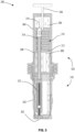
- the plug 200 includes a plug housing 202, a grip member 204, and a gland 206.
- the plug housing 202 is arranged to engage a mating receptacle 104 to complete a connection between the plug 200 and the receptacle 104.
- the gland 206 is partially illustrated in FIG. 2 and defines one end of the plug 200.
- the grip member 204 is connected to the plug housing 202 and provides a convenient gripping location for attaching or removing the plug 200 from the umbilical 102. In the illustrated construction, the grip member 204 is arranged for gripping by a remotely operated vehicle (ROV) with other arrangements being possible.
- ROV remotely operated vehicle
- FIG. 3 is a partial section view of the plug 200 of FIG. 2 taken through a center line that better illustrates the internal components of the plug 200.
- the plug 200 includes a plug end 318 and a dummy end 320 that attach to one another to complete the plug 200.
- the plug end 318 includes the plug housing 202 and one or more receptacle receivers 322 that are arranged to receive a corresponding receptacle pin (not shown). Each receptacle pin engages a pin interface 302 to initiate the electrical connection between the receptacle and the plug 200 as is well known in the art.
- the plug end includes three receptacle receivers 322 with each receptacle receiver 322 including a corresponding pin interface 302.
- Other constructions or plugs may include fewer or more receptacle receivers 322 and pin interfaces 302 as may be required by the particular application or arrangement.
- the dummy end 320 includes a compensated housing 304, a connection cartridge 310, and one or more contacts 308, with the illustrated construction including three contacts 308.
- the dummy end 320 connects to the plug housing 202 and defines an enclosed interior space that contains an insulating fluid 306 that is preferably a liquid such as oil.
- the contacts 308 extend into the interior space from an end of the compensated housing 304 nearest the plug end 318.
- Each of the contacts 308 includes a conducting region 316 that is formed at or near the end positioned most distant from the plug end 318.
- the conducting region 316 includes a slightly larger diameter than the remainder of the contact 308.
- the connection cartridge 310 includes a plurality of disks 312 stacked in a direction that is substantially parallel to a long axis of the contacts 308.
- the connection cartridge 310 defines one or more apertures 314 with each aperture 314 sized to receive one of the contacts 308.
- the connection cartridge 310 includes three apertures 314 arranged to allow the connection cartridge 310 to move linearly along the long axis of the contacts 308.
- the conducting region 316 of each contact 308 is sized to closely contact the interior of its respective aperture to allow for electrical conduction between the conducting region 316 and the disk 312 if such conduction is desired.
- the grip member 204 extends through the compensated housing 304 and connects to the connection cartridge 310. Linear movement of the grip member 204 along the long axis of the contact 308 produces a similar linear movement of the connection cartridge 310. As noted, the grip member 204 is arranged for grasping by a person, a ROV, or any other device or arrangement to produce the desired movement.
- FIG. 4 is an exploded view of the connection cartridge 310 illustrating one possible arrangement of disks 312.
- the connection cartridge 310 includes a plurality of disks 312 stacked along an axis parallel to the long axis of the contacts 308.
- Each disk 312 includes three disk holes 416 that pass through each respective disk 312 with each disk hole 416 cooperating with some of the disk holes 416 of the other disks 312 to define one of the apertures 314 and allow for the passage or receipt of one of the contacts 308 and its corresponding conducting region 316.
- a portion of the disks also include a conductor portion as will be discussed in greater detail.
- each of the disks 312 includes a number of disk holes 416 that corresponds to the number of contacts 308.
- the disks 312 could include fewer than three disk holes 416 and in arrangements with more than three contacts 308 the disks 312 would include more than three disk holes 416.
- connection cartridge 310 is arranged to engage the three contacts 308 which each extend from a bulkhead 402 that defines a portion of the plug housing 202, the compensated housing 304 or both.
- the connection cartridge 310 six disks 312 are stacked to define the connection cartridge 310. Most and preferably all the disks 312 are formed from an electrically non-conducting material.
- the disks 312 can be bonded to one another using any common technique including but not limited to welding, brazing, fasteners, or adhesives.
- Each disk 312 has a different arrangement to facilitate a different electrical connection between the contacts 308.
- the contacts 308 include an A-phase contact 428, a B-phase contact 430, and a C-phase contact 432 as might be used in a three-phase power system.
- the connection cartridge 310 of FIG. 4 includes an A-B disk 404, an A-C disk 406, a B-C disk 408, an ABC disk 410, a resistor disk 412, and an insulated disk 414 with more or fewer disks with different arrangements being possible.
- the A-B disk 404 includes a conductor portion in the form of an A-B conductor 418 that is coupled to the A-B disk 404 and provides an electrical connection between the disk hole 416 that is positioned to receive the A-phase contact 428 and the disk hole 416 that is positioned to receive the B-phase contact 430.
- the A-B conductor 418 is sized to make an electrical connection between the A-phase contact 428 and the B-phase contact 430 when the conducting regions 316 of the A-phase contact 428 and the B-phase contact 430 are disposed within the respective disk holes 416 of the A-B disk 404.
- the A-B conductor 418 may be attached to the A-B disk 404 using any common means including brazing, welding, fasteners, adhesives and the like. In some arrangements, the A-B conductor 418 is formed into or as part of the A-B disk 404 such that it cannot be removed without destroying or damaging the A-B disk 404.
- the A-C disk 406 and the B-C disk 408 are similar to the A-B disk 404 with the exception of the positioning of the A-C conductor 420 and the B-C conductor 422 with respect to the A-phase contact 428, the B-phase contact 430, and the C-phase contact 432.
- the A-C disk 406 and the B-C disk 408 can be identical to the A-B disk 404.
- the A-C disk 406 When assembled into the connection cartridge 310, the A-C disk 406 is rotated 120 degrees with respect to the A-B disk 404 and the B-C disk 408 is rotated another 120 degrees with respect to the A-C disk 406.
- Other constructions could employ different positions for the contacts 308 which would in turn require different positions or arrangements for the A-B disk 404, the A-C disk 406, and the B-C disk 408.
- the ABC disk 410 includes a conductor portion in the form of an ABC conductor 424 that electrically connects each of the three disk holes 416 formed in the ABC disk 410.
- the ABC conductor 424 can be connected to the ABC disk 410 in the same manner as described with regard to the A-B disk 404 or in another manner as may be desired.
- the ABC conductor 424 is arranged to make contact with the conducting region 316 of each of the A-phase contact 428, the B-phase contact 430, and the C-phase contact 432 when the conducting regions 316 are positioned within the ABC disk 410.
- the ABC disk 410 connects each of the phases of the three-phase power system in a Delta configuration.
- the material or arrangement of the ABC conductor 424 can be selected to provide a desired level of resistance between the phases of the three-phase power system.
- the resistor disk 412 includes a conductor portion in the form of a star-linked resistor arrangement 426 that connects the three disk holes 416 in a star or wye configuration.
- the star-linked resistor arrangement 426 can be attached to the resistor disk 412 in any desired manner including, for example an adhesive or epoxy.
- the star-linked resistor arrangement 426 is embedded in the resistor disk 412.
- the insulated disk 414 includes three disk holes 416 that are electrically insulated from one another by the material of the insulated disk 414.
- the conducting regions 316 of the A-phase contact 428, the B-phase contact 430, and the C-phase contact 432 are positioned within the disk holes 416 of the insulated disk 414, the three phases are insulated or isolated from one another.
- Some constructions may omit the insulated disk 414 and simply allow the conducting regions 316 of the various contacts 308 are outside of any disks 312 and therefore electrically separated from one another or even insulated from one another by the insulating fluid 306 within the compensated housing 304.
- connection cartridge 310 the order of the disks 312 within the connection cartridge 310 is not relevant to the operation of the device as any order could be employed. In addition, fewer or more disks that provide different connections or additional circuit elements could be employed if desired.
- FIG. 3 shows the connection cartridge 310 in a first position
- FIG. 5 shows the connection cartridge 310 in a second position.
- the plug 200 is in the first position where the conducting regions 316 of each of the contacts 308 is positioned within the B-C disk 408 such that the B-phase contact 430 and the C-phase contact 432 are electrically connected to one another and the A-phase contact 428 is insulated from the B-phase contact 430 and the C-phase contact 432.
- a user or a tool such as a ROV grabs or grips the grip member 204 and moves the grip member 204 linearly along the adjustment axis 502 to adjust the position of the connection cartridge 310 with respect to the conducting regions 316.
- a grip member 204 is pushed toward the plug 200 to move the connection cartridge 310 toward the plug end 318.
- connection cartridge 310 moves the conducting region 316 of each of the contacts 308 from a position within the disk holes 416 of the B-C disk 408 to a position within the disk holes 416 of the resistor disk 412, thereby transitioning the three-phase power system from a condition in which the B-phase contact 430 and the C-phase contact 432 are connected and the A-phase contact 428 is insulated to a condition in which each of the A-phase contact 428, the B-phase contact 430, and the C-phase contact 432 are connected in a star or wye arrangement. Similar linear movement allows a user or tool to selectively move the connection cartridge 310 to connect or isolate the A-phase contact 428, the B-phase contact 430, and the C-phase contact 432 using any of the disks 312 provided.
- FIG. 6 illustrates another arrangement of a plug 600 where adjustment of the connection cartridge 310 is made through rotation of a rotary handle 602 rather than through translation of the grip member 204.
- the rotary handle 602 is still rotated by a user, a tool, or an ROV.
- an indicator 604 can be provided to help guide a user as the rotary handle 602 is rotated.
- a similar indicator 604 could be provided in the construction of FIG. 5 if desired.
- the plug 600 includes a mechanism for converting the rotary motion of the rotary handle 602 into linear translation of the connection cartridge 310 as was described previously.
- Suitable mechanisms could include rack and pinion systems, gear arrangements, screw arrangements (lead screws, ball screws, etc.), linkages such as crank and slider mechanisms, Scotch yokes, magnets, and the like.
- rotary handle 602 is illustrated extending from the end of the compensated housing 304, other arrangements could position the rotary handle 602 at a ninety-degree orientation to that shown such that it extends in a direction normal to the adjustment axis 502 of FIG. 5 . As discussed, similar mechanisms could be employed to convert the rotary motion to linear motion of the connection cartridge 310.
- the plugs 200, 600 illustrated herein are advantageous as a single plug can be used to make multiple different connections as may be required for any application. Rather than having different plugs for each desired circuit, the plug 200, 600 can be configured for the desired circuit and installed. If for some reason, the desired circuit changes, the plug can be transitioned to the new circuit arrangement without removing or disconnecting the plug 200, 600 from the receptacle.
- FIG. 7 broadly illustrates a method of changing an electrical connection 700 and particularly a method of changing an electrical connection 700 in an underwater connection.
- the method of changing an electrical connection 700 connects the plug 200, 600 to the receptacle along an axis.
- the method of changing an electrical connection 700 positions the connection cartridge 310 disposed within the plug 200, 600 in a first position, the first position defining a first connection arrangement between a first contact, a second contact, and a third contact disposed within the plug 200, 600.
- the method of changing an electrical connection 700 moves a handle or grip member 204 without disconnecting the plug 200, 600 from the receptacle to move the connection cartridge 310 to a second position, the second position defining a second connection arrangement between the first contact, the second contact, and the third contact that is different from the first connection arrangement.
Landscapes
- Engineering & Computer Science (AREA)
- Manufacturing & Machinery (AREA)
- Power Engineering (AREA)
- Connector Housings Or Holding Contact Members (AREA)
Applications Claiming Priority (1)
| Application Number | Priority Date | Filing Date | Title |
|---|---|---|---|
| GB2303003.4A GB2627778B (en) | 2023-03-01 | 2023-03-01 | Plug for a connector |
Publications (1)
| Publication Number | Publication Date |
|---|---|
| EP4425721A1 true EP4425721A1 (fr) | 2024-09-04 |
Family
ID=85793956
Family Applications (1)
| Application Number | Title | Priority Date | Filing Date |
|---|---|---|---|
| EP24160765.4A Pending EP4425721A1 (fr) | 2023-03-01 | 2024-03-01 | Fiche pour un connecteur sous-marin et méthode de changement de connexion sous-marine entre une fiche et un réceptacle |
Country Status (3)
| Country | Link |
|---|---|
| US (1) | US12627099B2 (fr) |
| EP (1) | EP4425721A1 (fr) |
| GB (1) | GB2627778B (fr) |
Citations (4)
| Publication number | Priority date | Publication date | Assignee | Title |
|---|---|---|---|---|
| US20050116799A1 (en) * | 2002-03-25 | 2005-06-02 | Vetco Aibel As | Switching device |
| US20080284160A1 (en) * | 2005-11-23 | 2008-11-20 | Jarl Voster | Coupling Device and a Method of Using Same |
| EP2853680A1 (fr) * | 2013-09-30 | 2015-04-01 | Siemens Aktiengesellschaft | Système de chasse d'eau |
| CN111463624A (zh) * | 2020-04-02 | 2020-07-28 | 中国船舶科学研究中心(中国船舶重工集团公司第七0二研究所) | 一种可带电插拔的水下湿式电连接器 |
Family Cites Families (5)
| Publication number | Priority date | Publication date | Assignee | Title |
|---|---|---|---|---|
| US8215013B2 (en) * | 2008-04-11 | 2012-07-10 | Bal Seal Engineering, Inc. | Method for making a free standing axially compressed connector stack |
| US7959454B2 (en) * | 2009-07-23 | 2011-06-14 | Teledyne Odi, Inc. | Wet mate connector |
| US8267707B2 (en) * | 2010-02-03 | 2012-09-18 | Tronic Limited | Underwater or sub sea connectors |
| DE102014115396A1 (de) * | 2014-10-22 | 2014-12-18 | Peter Lell | Trennschalter für hohe Gleich- oder Wechselströme bei hohen Spannungen |
| CA2946682C (fr) * | 2015-10-27 | 2022-04-05 | Extensive Energy Technologies Partnership | Systeme de raccord rotatif a loquet |
-
2023
- 2023-03-01 GB GB2303003.4A patent/GB2627778B/en active Active
-
2024
- 2024-02-02 US US18/430,901 patent/US12627099B2/en active Active
- 2024-03-01 EP EP24160765.4A patent/EP4425721A1/fr active Pending
Patent Citations (4)
| Publication number | Priority date | Publication date | Assignee | Title |
|---|---|---|---|---|
| US20050116799A1 (en) * | 2002-03-25 | 2005-06-02 | Vetco Aibel As | Switching device |
| US20080284160A1 (en) * | 2005-11-23 | 2008-11-20 | Jarl Voster | Coupling Device and a Method of Using Same |
| EP2853680A1 (fr) * | 2013-09-30 | 2015-04-01 | Siemens Aktiengesellschaft | Système de chasse d'eau |
| CN111463624A (zh) * | 2020-04-02 | 2020-07-28 | 中国船舶科学研究中心(中国船舶重工集团公司第七0二研究所) | 一种可带电插拔的水下湿式电连接器 |
Also Published As
| Publication number | Publication date |
|---|---|
| GB2627778A (en) | 2024-09-04 |
| US20240297461A1 (en) | 2024-09-05 |
| GB202303003D0 (en) | 2023-04-12 |
| GB2627778B (en) | 2025-03-12 |
| US12627099B2 (en) | 2026-05-12 |
Similar Documents
| Publication | Publication Date | Title |
|---|---|---|
| CA2428338C (fr) | Connecteur modulaire integre pour tube de forage | |
| US7828593B2 (en) | Shielded oilfield electric connector | |
| WO1999034495A1 (fr) | Dispositif de raccordement d'un cable | |
| JP2004519979A (ja) | 可撓性ケーブルを多様な形態の任意の剛性デバイスに接続するためのユニバーサルパワーコネクタ | |
| US10938145B2 (en) | Systems and methods for sealing motor lead extensions | |
| CN100459343C (zh) | 绝缘母线系统及其母线单元的连接方法 | |
| US12627099B2 (en) | Plug for a connector | |
| GB2581958A (en) | Two-part and terminal connectors with conductor management device for use in hazardous environments | |
| US7326865B2 (en) | Switching device | |
| US9028280B2 (en) | Electrical three-phase power connector | |
| US20220238258A1 (en) | Electrical feedthrough system and methods of use thereof | |
| US20260071511A1 (en) | Harness | |
| EP3927931B1 (fr) | Système de traversée électrique et ses procédés d'utilisation | |
| US4527847A (en) | Mounting assembly for rotatable electrical connector | |
| CN119008283B (zh) | 一种全海深水下装备自动短路开关及其制造方法 | |
| EP4728599A1 (fr) | Ensemble sous-marin haute tension | |
| CN118979886A (zh) | 一种水下智能电气切换器 | |
| CN1881719B (zh) | 用于导电连接中压设备配电板的装置 | |
| GB2623425A (en) | Harness | |
| Wilson | Underwater mateable electromechanical connectors for power and signal cables | |
| Briggs et al. | A" Wet" and" Dry" Deep Submergence Electrical Power Transmission System. Phase 2. Volume 2 | |
| Hosom | Oil Filled Electrical Cables External to the Pressure Hull on DSV ALVIN | |
| Aubin | Design and Test Results of a New Generation of High-Reliability Long Distance Subsea Remote Control System | |
| WO2018231972A1 (fr) | Câbles électriques et de commande à isolement minéral destinés à des applications sous-marines |
Legal Events
| Date | Code | Title | Description |
|---|---|---|---|
| PUAI | Public reference made under article 153(3) epc to a published international application that has entered the european phase |
Free format text: ORIGINAL CODE: 0009012 |
|
| STAA | Information on the status of an ep patent application or granted ep patent |
Free format text: STATUS: REQUEST FOR EXAMINATION WAS MADE |
|
| 17P | Request for examination filed |
Effective date: 20240301 |
|
| AK | Designated contracting states |
Kind code of ref document: A1 Designated state(s): AL AT BE BG CH CY CZ DE DK EE ES FI FR GB GR HR HU IE IS IT LI LT LU LV MC ME MK MT NL NO PL PT RO RS SE SI SK SM TR |