EP4425767A1 - Moteur électrique à engrenage pour une bicyclette - Google Patents
Moteur électrique à engrenage pour une bicyclette Download PDFInfo
- Publication number
- EP4425767A1 EP4425767A1 EP23181626.5A EP23181626A EP4425767A1 EP 4425767 A1 EP4425767 A1 EP 4425767A1 EP 23181626 A EP23181626 A EP 23181626A EP 4425767 A1 EP4425767 A1 EP 4425767A1
- Authority
- EP
- European Patent Office
- Prior art keywords
- hub
- pedal device
- electric pedal
- core
- coupled
- Prior art date
- Legal status (The legal status is an assumption and is not a legal conclusion. Google has not performed a legal analysis and makes no representation as to the accuracy of the status listed.)
- Pending
Links
Images


Classifications
-
- B—PERFORMING OPERATIONS; TRANSPORTING
- B62—LAND VEHICLES FOR TRAVELLING OTHERWISE THAN ON RAILS
- B62M—RIDER PROPULSION OF WHEELED VEHICLES OR SLEDGES; POWERED PROPULSION OF SLEDGES OR SINGLE-TRACK CYCLES; TRANSMISSIONS SPECIALLY ADAPTED FOR SUCH VEHICLES
- B62M6/00—Rider propulsion of wheeled vehicles with additional source of power, e.g. combustion engine or electric motor
- B62M6/40—Rider propelled cycles with auxiliary electric motor
- B62M6/55—Rider propelled cycles with auxiliary electric motor power-driven at crank shafts parts
-
- B—PERFORMING OPERATIONS; TRANSPORTING
- B62—LAND VEHICLES FOR TRAVELLING OTHERWISE THAN ON RAILS
- B62M—RIDER PROPULSION OF WHEELED VEHICLES OR SLEDGES; POWERED PROPULSION OF SLEDGES OR SINGLE-TRACK CYCLES; TRANSMISSIONS SPECIALLY ADAPTED FOR SUCH VEHICLES
- B62M11/00—Transmissions characterised by the use of interengaging toothed wheels or frictionally-engaging wheels
- B62M11/04—Transmissions characterised by the use of interengaging toothed wheels or frictionally-engaging wheels of changeable ratio
- B62M11/14—Transmissions characterised by the use of interengaging toothed wheels or frictionally-engaging wheels of changeable ratio with planetary gears
- B62M11/145—Transmissions characterised by the use of interengaging toothed wheels or frictionally-engaging wheels of changeable ratio with planetary gears built in, or adjacent to, the bottom bracket
-
- B—PERFORMING OPERATIONS; TRANSPORTING
- B62—LAND VEHICLES FOR TRAVELLING OTHERWISE THAN ON RAILS
- B62M—RIDER PROPULSION OF WHEELED VEHICLES OR SLEDGES; POWERED PROPULSION OF SLEDGES OR SINGLE-TRACK CYCLES; TRANSMISSIONS SPECIALLY ADAPTED FOR SUCH VEHICLES
- B62M11/00—Transmissions characterised by the use of interengaging toothed wheels or frictionally-engaging wheels
- B62M11/04—Transmissions characterised by the use of interengaging toothed wheels or frictionally-engaging wheels of changeable ratio
- B62M11/14—Transmissions characterised by the use of interengaging toothed wheels or frictionally-engaging wheels of changeable ratio with planetary gears
- B62M11/18—Transmissions characterised by the use of interengaging toothed wheels or frictionally-engaging wheels of changeable ratio with planetary gears with a plurality of planetary gear units
-
- B—PERFORMING OPERATIONS; TRANSPORTING
- B62—LAND VEHICLES FOR TRAVELLING OTHERWISE THAN ON RAILS
- B62M—RIDER PROPULSION OF WHEELED VEHICLES OR SLEDGES; POWERED PROPULSION OF SLEDGES OR SINGLE-TRACK CYCLES; TRANSMISSIONS SPECIALLY ADAPTED FOR SUCH VEHICLES
- B62M6/00—Rider propulsion of wheeled vehicles with additional source of power, e.g. combustion engine or electric motor
- B62M6/80—Accessories, e.g. power sources; Arrangements thereof
-
- H—ELECTRICITY
- H02—GENERATION; CONVERSION OR DISTRIBUTION OF ELECTRIC POWER
- H02K—DYNAMO-ELECTRIC MACHINES
- H02K1/00—Details of the magnetic circuit
- H02K1/06—Details of the magnetic circuit characterised by the shape, form or construction
- H02K1/12—Stationary parts of the magnetic circuit
- H02K1/18—Means for mounting or fastening magnetic stationary parts on to, or to, the stator structures
- H02K1/187—Means for mounting or fastening magnetic stationary parts on to, or to, the stator structures to inner stators
-
- H—ELECTRICITY
- H02—GENERATION; CONVERSION OR DISTRIBUTION OF ELECTRIC POWER
- H02K—DYNAMO-ELECTRIC MACHINES
- H02K11/00—Structural association of dynamo-electric machines with electric components or with devices for shielding, monitoring or protection
- H02K11/30—Structural association with control circuits or drive circuits
- H02K11/33—Drive circuits, e.g. power electronics
-
- H—ELECTRICITY
- H02—GENERATION; CONVERSION OR DISTRIBUTION OF ELECTRIC POWER
- H02K—DYNAMO-ELECTRIC MACHINES
- H02K21/00—Synchronous motors having permanent magnets; Synchronous generators having permanent magnets
- H02K21/12—Synchronous motors having permanent magnets; Synchronous generators having permanent magnets with stationary armatures and rotating magnets
- H02K21/22—Synchronous motors having permanent magnets; Synchronous generators having permanent magnets with stationary armatures and rotating magnets with magnets rotating around the armatures, e.g. flywheel magnetos
-
- H—ELECTRICITY
- H02—GENERATION; CONVERSION OR DISTRIBUTION OF ELECTRIC POWER
- H02K—DYNAMO-ELECTRIC MACHINES
- H02K7/00—Arrangements for handling mechanical energy structurally associated with dynamo-electric machines, e.g. structural association with mechanical driving motors or auxiliary dynamo-electric machines
- H02K7/006—Structural association of a motor or generator with the drive train of a motor vehicle
-
- H—ELECTRICITY
- H02—GENERATION; CONVERSION OR DISTRIBUTION OF ELECTRIC POWER
- H02K—DYNAMO-ELECTRIC MACHINES
- H02K7/00—Arrangements for handling mechanical energy structurally associated with dynamo-electric machines, e.g. structural association with mechanical driving motors or auxiliary dynamo-electric machines
- H02K7/10—Structural association with clutches, brakes, gears, pulleys or mechanical starters
- H02K7/116—Structural association with clutches, brakes, gears, pulleys or mechanical starters with gears
- H02K7/1163—Structural association with clutches, brakes, gears, pulleys or mechanical starters with gears where at least two gears have non-parallel axes without having orbital motion
-
- H—ELECTRICITY
- H02—GENERATION; CONVERSION OR DISTRIBUTION OF ELECTRIC POWER
- H02K—DYNAMO-ELECTRIC MACHINES
- H02K1/00—Details of the magnetic circuit
- H02K1/06—Details of the magnetic circuit characterised by the shape, form or construction
- H02K1/22—Rotating parts of the magnetic circuit
- H02K1/27—Rotor cores with permanent magnets
- H02K1/2786—Outer rotors
- H02K1/2787—Outer rotors the magnetisation axis of the magnets being perpendicular to the rotor axis
- H02K1/2788—Outer rotors the magnetisation axis of the magnets being perpendicular to the rotor axis the rotor consisting of a single magnet or two or more axially juxtaposed single magnets
-
- H—ELECTRICITY
- H02—GENERATION; CONVERSION OR DISTRIBUTION OF ELECTRIC POWER
- H02K—DYNAMO-ELECTRIC MACHINES
- H02K2211/00—Specific aspects not provided for in the other groups of this subclass relating to measuring or protective devices or electric components
- H02K2211/03—Machines characterised by circuit boards, e.g. pcb
Definitions
- Embodiments of the present disclosure relate to an electric pedal device in which an axial deviation of a core lamination is prevented.
- Electric bicycles enable comfortable riding on flat ground and uphill roads by attaching a DC motor to a wheel hub or crankshaft of a general bicycle and assisting with power.
- the standard for the scope of application of electric bicycles refers to two-wheeled bicycles equipped with electric motor power to supplement human power.
- Electric bicycles refer to bicycles that surely have a pedal driving function and move with the power of an electric motor.
- the electric bicycles can be classified into, firstly, throttle: a bicycle that moves only with the power of an electric motor by manipulating an electric bicycle accelerator lever, secondly, a pedal assist system (PAS): a bicycle that moves with the simultaneous power of an electric bicycle pedal and an electric motor, and thirdly, throttle/PAS: a bicycle that supports both the throttle and PAS driving methods of electric bicycles.
- throttle a bicycle that moves only with the power of an electric motor by manipulating an electric bicycle accelerator lever
- PAS pedal assist system
- throttle/PAS a bicycle that supports both the throttle and PAS driving methods of electric bicycles.
- an electric pedal device which forms a reaction force when a cyclist pedals and generates electric energy by pedaling. It is another aspect of the present disclosure to provide an electric pedal device to which a structure for preventing axial deviation of a core lamination in a stator core for generating electric energy is applied.
- an electric pedal device includes a housing configured to form a space therein, a rotating shaft disposed to pass through the housing, a reduction gear set configured to reduce a rotational force of the rotating shaft, a rotor core configured to rotate by an output of the reduction gear set, a stator core including a hub and a core lamination coupled to the hub and having a structure preventing axial deviation of the hub, and a circuit substrate electrically connected to the stator core and fixed to the housing.
- the hub may be formed at a center of the core lamination that is hollow by an insert casting method.
- the hub may include insert portions inserted into the grooves, an upper locking jaw supporting an upper side of the core lamination, and a lower locking jaw supporting a lower side of the core lamination.
- the hub may include a top having a triangular prism shape and a bottom having a cylindrical shape and having grooves extending downward in the axial direction from the top, and a protrusion extending in the axial direction and fitted into each of the grooves may be formed on the inner circumferential surface of the core lamination
- the bottom may include the upper locking jaw supporting the upper side of the core lamination, and the lower locking jaw supporting the lower side of the core lamination.
- a plurality of staking portions formed to be bent outward in a radial direction may be formed on the bottom.
- the stator core may further include a lock nut to be fastened to an upper side of the hub.
- the hub may include a top having a triangular prism shape and a bottom having a cylindrical shape and having a plurality of grooves at a corner side.
- the lock nut may include a plurality of caulking portions formed with flat surfaces.
- the caulking portions may be configured to be deformed and inserted into the grooves after the lock nut is fastened to the hub.
- the stator core may have the hub and the core lamination integrally formed to prevent the axial deviation of the hub.
- the reduction gear set may include a first carrier coupled to the rotating shaft, a plurality of first planetary gears rotatably coupled to the first carrier, and a first ring gear coupled to the housing and meshing with the first planetary gear.
- the reduction gear set may further include a second carrier rotating relative to the rotating shaft, a first sun gear formed on one surface of the second carrier and meshing with the first planetary gear, a plurality of second planetary gears rotatably coupled to the other surface of the second carrier, and a second ring gear coupled to the housing and meshing with the second planetary gear.
- the reduction gear set may further include a second sun gear meshing with the second planetary gear, and the rotor core may be coupled to the second sun gear and configured to be interlocked with a rotation of the second sun gear.
- FIG. 1 is a perspective view showing an electric pedal device 1 according to an embodiment of the present disclosure.
- FIG. 2 is a perspective view showing the inside of the electric pedal device 1 shown in FIG. 1 .
- FIG. 3 is a cross-sectional view of the electric pedal device 1 shown in FIG. 1 .
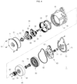
- FIG. 4 is an exploded perspective view of the electric pedal device 1 shown in FIG. 1 .
- the electric pedal device 1 may include a housing 10 configured to form a space therein, a rotating shaft 20 disposed to pass through the housing 10, a reduction gear set 30 configured to reduce a rotational force of the rotating shaft 20, a rotor core 40 configured to rotate by an output of the reduction gear set 30, a stator core 50 that includes a hub 100 and a core lamination 110 coupled to the hub 100 and has a structure for preventing axial deviation of the hub 100, and a circuit substrate 60 electrically connected to the stator core 50 and fixed to the housing 10.
- the circuit substrate 60 may include a connector 61.
- the rotating shaft 20 is rotated by a user's pedaling, and a rotational force of the rotating shaft 20 rotates the rotor core 40, thereby producing electrical energy in the stator core 50.
- the electrical energy produced in this manner may be stored in an externally disposed battery (not shown).
- the housing 10 may include a first cover 11 close to the reduction gear set 30, a housing body 12, and a second cover 13 to which the circuit substrate 60 is fixed.
- the housing body 12 may have a cylindrical shape.
- the housing body 12 may include a mounting part 16 for being coupled to a bicycle frame (not shown).
- the hub 100 of the stator core 50 may be coupled to a coupler 17 of the housing 10 configured to penetrate the circuit substrate 60.
- the coupler 17 may be formed inside the second cover 13.
- the hub 100 may be coupled to the coupler 17 by a bolt 83.
- the bolt 83 may penetrate the coupler 17 from an outside of the second cover 13 and may be fastened to a fastening hole 102 (refer to FIG. 6 ) formed in the hub 100.
- the reduction gear set 30 includes a first carrier 31 coupled to the rotating shaft 20, a plurality of first planetary gears 32 rotatably coupled to the first carrier 31, and a first ring gear 33 coupled to the housing body 12 and meshing with the first planetary gear 32.
- the first carrier 31 may be coupled to the rotating shaft 20 by a key 81 and interlock with the rotation of the rotating shaft 20.
- a bearing 71 may be interposed between the first cover 11 and the first carrier 31.
- a rotating shaft 38 may be coupled to the first carrier 31, and a bearing 72 may be interposed between the rotating shaft 38 and the first planetary gear 32.
- the reduction gear set 30 may further include a second carrier 34 configured to rotate relative to the rotating shaft 20, a first sun gear 35 formed on one surface of the second carrier 34 and meshing with the first planetary gear 32, a plurality of second planetary gears 36 rotatably coupled to the other surface of the second carrier 34, and a second ring gear 37 coupled to the housing body 12 and meshing with the second planetary gear 36.
- a rotating shaft 39 may be coupled to the second carrier 34, and a bearing 73 may be interposed between the rotating shaft 39 and the second planetary gear 36.
- the reduction gear set 30 may include a second sun gear 41 meshing with the second planetary gear 36.
- the rotor core 40 may be configured to be coupled to the second sun gear 41 and interlocked with the rotation of the second sun gear 41.
- a frame unit 41 may be coupled to the second sun gear 41 by a bolt 82.
- a bearing 74 and a bearing 75 may be interposed between the frame unit 41 and the rotating shaft 20.
- a magnetic body 42 may be attached to an inner circumferential surface of the frame unit 41 of the rotor core 40.
- the stator core 50 may be configured to generate power when the magnetic body 42 of the rotor core 40 rotates.
- a coil winding 120 may be coupled to the core lamination 110.
- a bearing 76 may be interposed between the hub 100 and the rotating shaft 20. Therefore, the rotation of the rotating shaft 20 does not affect a position of the stator core 50.
- a bearing 77 may be interposed between the rotating shaft 20 and the coupler 17.
- the first cover 11 may be coupled to the housing body 12 by a bolt 14.
- the second cover 13 may be coupled to the housing body 12 by a bolt 15.
- a sealing portion 91 may be interposed between the first cover 11 and the housing body 12.
- a sealing portion 92 may also be interposed between the second cover 13 and the housing body 12.
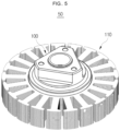
- FIG. 5 is a perspective view showing the stator core 50 integrally formed by an insert casting method.
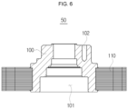
- FIG. 6 is a cross-sectional view of the stator core 50 shown in FIG. 5 .
- FIG. 7 is a view showing the core lamination 110 of the stator core shown in FIG. 5 .
- FIG. 8 is a view showing the hub 100 of the stator core 50 shown in FIG. 5 .
- the hub 100 and the core lamination 110 may be integrally formed by a lowtemperature insert casting method.
- the hub 100 may be formed by casting from a molten metal at a center of the core lamination 110 that is hollow.
- the hub 100 may be integrated with the core lamination 110 by being inserted and casted in a low-pressure casting method, and thus it is possible to prevent the core lamination 110 from being axially separated from the hub 100 and to have a structure for preventing the rotation of the core lamination 110 through its own shape.
- a plurality of grooves 111 extending in the axial direction may be formed on an inner circumferential surface of the core lamination 110.
- insert portions 103 inserted into the grooves 111 may be formed.
- a through portion 101 through which the rotating shaft 20 passes may be formed at a center of the hub 100, and the fastening hole 102 may be formed at an upper side of the hub 100.
- the hub 100 may include an upper locking jaw 104 supporting an upper side of the core lamination 110 and a lower locking jaw 105 supporting a lower side of the core lamination 110. Since the integrally formed hub 100 supports the upper and lower sides of the core lamination 110, axial deviation of the core lamination 110 relative to the hub 100 may be prevented.
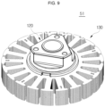
- FIG. 9 is a perspective view showing a stator core 51 in which a hub 120 is coupled to a core lamination 130.
- FIG. 10 is an exploded perspective view of the stator core 51 shown in FIG. 9 .
- FIG. 11 is a bottom view of the stator core 51 shown in FIG. 9 .
- FIG. 12 is a view for describing a staking portion 126 shown in FIG. 11 . Duplicated descriptions of contents described in the embodiment described above will be omitted.
- the hub 120 may include a top 121 having a triangular prism shape and a bottom 122 having a cylindrical shape and having grooves 123 extending downward in the axial direction from the top 121. Protrusions 131 extending in the axial direction and fitted into the grooves 123 may be formed on an inner circumferential surface of the core lamination 130.
- the bottom 122 may include an upper locking jaw 124 supporting an upper side of the core lamination 130 and a lower locking jaw 125 supporting a lower side of the core lamination 130.
- These grooves 123 may have the same shape as two keys, and may prevent the rotation of the core lamination 130 relative to the hub 120.
- a plurality of staking portions 126 which are formed to be bent outward in the radial direction, may be formed on a lower surface of the bottom 122.
- the staking portion 126 can prevent axial deviation of the core lamination 130 more firmly.
- FIG. 12 a shape of the staking portion 126 can be confirmed.
- internal rotational force may be increased through the staking portion 126.
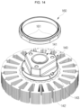
- FIG. 13 is a perspective view showing a stator core 52 to which a lock nut 160 is coupled.
- FIG. 14 is a perspective view showing a state in which the lock nut 160 is separated from a hub 140 in FIG. 13 .
- FIG. 15 is a view showing a state in which grooves 143 are formed in the hub 140 in FIG. 13 .
- the stator core 52 may include the hub 140, a core lamination 150, and the lock nut 160 fastened to an upper side of the hub 140.
- the hub 140 may include a top 141 having a triangular prism shape and a bottom 142 having a cylindrical shape and having a plurality of grooves 143 formed at the corner side.
- FIG. 15 is a view of a state in which the grooves 143 are formed, which is photographed from the upper side, and FIG. 16 is an enlarged view of portion I of FIG. 15 . Referring to these, the state in which the grooves 143 are formed can be confirmed.
- the lock nut 160 may include a plurality of caulking portions 161 formed with flat surfaces.
- the caulking portions 161 may be configured to be deformed after the lock nut 160 is fastened to the hub 140 and inserted into the grooves 143.
- the caulking portion 161 may be deformed inward in the radial direction, thereby preventing axial deviation of the core lamination 150.
- a method of fixing the core lamination 150 of the stator core 52 so as not to be axially separated from the hub 140 can be implemented by an assembly structure that forms the caulking portion 161 after the lock nut 160 is fastened.
- a structure in which a core lamination and an aluminum hub are integrated in an insert die-casting method is used in the electric pedal device, but in the present embodiment, it is derived by approaching the assembly structure side.
- the core lamination can be firstly fixed in the axial direction by fastening the lock nut 160 using sufficient torque, and loosening torque can be increased by forming the caulking portion 161 secondly.
- the lock nut 160 may have a tab shape corresponding to the screw shape of the hub 140, and the lock nut 160 may have a thin thickness so as to be folded after being caulked. In addition, when the lock nut 160 has a backside width shape, it can be fastened to the hub 140 using a tool.
- such a structure can be presented as a prefabricated coupling structure using other parts such as a lock nut in a situation where insert die-casting is difficult to apply.
- An electric pedal device is formed by injecting a hub into a core lamination in a low-pressure insert casting method, and thus a coupling between the core lamination and the hub can be strengthened during the injection process.
- axial deviation of a core lamination can be prevented by forming a stacking portion on a hub with a core coupled to the core lamination.
- axial deviation of a core lamination can be prevented by fastening a lock nut to a hub and forming a caulking portion with the core coupled to the core lamination.
Landscapes
- Engineering & Computer Science (AREA)
- Chemical & Material Sciences (AREA)
- Combustion & Propulsion (AREA)
- Power Engineering (AREA)
- Transportation (AREA)
- Mechanical Engineering (AREA)
- Microelectronics & Electronic Packaging (AREA)
- Connection Of Motors, Electrical Generators, Mechanical Devices, And The Like (AREA)
- Iron Core Of Rotating Electric Machines (AREA)
Applications Claiming Priority (1)
| Application Number | Priority Date | Filing Date | Title |
|---|---|---|---|
| KR1020230028542A KR20240135237A (ko) | 2023-03-03 | 2023-03-03 | 전기 페달 장치 |
Publications (1)
| Publication Number | Publication Date |
|---|---|
| EP4425767A1 true EP4425767A1 (fr) | 2024-09-04 |
Family
ID=87003095
Family Applications (1)
| Application Number | Title | Priority Date | Filing Date |
|---|---|---|---|
| EP23181626.5A Pending EP4425767A1 (fr) | 2023-03-03 | 2023-06-27 | Moteur électrique à engrenage pour une bicyclette |
Country Status (2)
| Country | Link |
|---|---|
| EP (1) | EP4425767A1 (fr) |
| KR (1) | KR20240135237A (fr) |
Citations (7)
| Publication number | Priority date | Publication date | Assignee | Title |
|---|---|---|---|---|
| US20030098628A1 (en) * | 2001-11-29 | 2003-05-29 | Yuuji Enomoto | Electric motor |
| US20120161495A1 (en) * | 2010-12-24 | 2012-06-28 | Shimano Inc. | Internal motorized bicycle hub |
| US8575871B1 (en) * | 2010-07-23 | 2013-11-05 | Christopher Moore | Modular component electric machine |
| KR20140005169A (ko) | 2010-11-10 | 2014-01-14 | 스테픈 소에흐너 게엠베하 | 전기 디스크 회전자 모터 및 디스크 회전자 모터를 포함하는 전기 자전거 또는 페달식 전기 자전거 |
| EP3480102A1 (fr) * | 2016-07-01 | 2019-05-08 | Wuhan Ttium Motor Technology Co., Ltd. | Moteur intégré pour bicyclette et bicyclette électrique |
| DE102021109498A1 (de) * | 2020-04-17 | 2021-10-21 | Shinano Kenshi Kabushiki Kaisha | AUßENLÄUFERMOTOR |
| US20220320927A1 (en) * | 2019-12-13 | 2022-10-06 | Denso Corporation | Rotating electrical machine |
-
2023
- 2023-03-03 KR KR1020230028542A patent/KR20240135237A/ko active Pending
- 2023-06-27 EP EP23181626.5A patent/EP4425767A1/fr active Pending
Patent Citations (7)
| Publication number | Priority date | Publication date | Assignee | Title |
|---|---|---|---|---|
| US20030098628A1 (en) * | 2001-11-29 | 2003-05-29 | Yuuji Enomoto | Electric motor |
| US8575871B1 (en) * | 2010-07-23 | 2013-11-05 | Christopher Moore | Modular component electric machine |
| KR20140005169A (ko) | 2010-11-10 | 2014-01-14 | 스테픈 소에흐너 게엠베하 | 전기 디스크 회전자 모터 및 디스크 회전자 모터를 포함하는 전기 자전거 또는 페달식 전기 자전거 |
| US20120161495A1 (en) * | 2010-12-24 | 2012-06-28 | Shimano Inc. | Internal motorized bicycle hub |
| EP3480102A1 (fr) * | 2016-07-01 | 2019-05-08 | Wuhan Ttium Motor Technology Co., Ltd. | Moteur intégré pour bicyclette et bicyclette électrique |
| US20220320927A1 (en) * | 2019-12-13 | 2022-10-06 | Denso Corporation | Rotating electrical machine |
| DE102021109498A1 (de) * | 2020-04-17 | 2021-10-21 | Shinano Kenshi Kabushiki Kaisha | AUßENLÄUFERMOTOR |
Also Published As
| Publication number | Publication date |
|---|---|
| KR20240135237A (ko) | 2024-09-10 |
Similar Documents
| Publication | Publication Date | Title |
|---|---|---|
| EP1918150B1 (fr) | Appareil de contrôle pour véhicule hybride | |
| US12021427B2 (en) | Motor, vehicle power unit with motor, generator, vehicle wheel bearing with generator | |
| EP2921397B1 (fr) | Moteur au moyen de roue pour vélo électrique et vélo électrique comprenant ce moteur | |
| US8702549B2 (en) | Vehicle drive unit | |
| US6260644B1 (en) | Motor controlling apparatus for a hybrid car | |
| JP7156787B2 (ja) | 車輪用軸受装置およびこの車輪用軸受装置を備えた車両 | |
| US20130284527A1 (en) | Electric vehicle | |
| US20020170757A1 (en) | Hybrid vehicle | |
| JP2012502835A (ja) | 小型電動車における中間取付けモータ駆動装置 | |
| US20230094579A1 (en) | Vehicle power device and wheel bearing with generator | |
| US20230098893A1 (en) | Vehicle power device and vehicle bearing with power generator | |
| CN110425072A (zh) | 用于内燃发动机的起动机 | |
| JP3097482B2 (ja) | リターダ装置 | |
| JP2009033939A (ja) | 動力装置 | |
| CN113396523A (zh) | 具有电动机的车辆用动力装置和具有发动机的带有发电机的车轮用轴承装置 | |
| EP4425767A1 (fr) | Moteur électrique à engrenage pour une bicyclette | |
| US20130140930A1 (en) | Electric rotating machine and method for manufacturing a stator core for the electric rotating machine | |
| JP2003191759A (ja) | ハイブリッド車両用駆動装置 | |
| JP2019205241A (ja) | 三相永久磁石同期モータおよびこの三相永久磁石同期モータを備えた車両用動力装置、発電機およびこの発電機を備えた発電機付車輪用軸受 | |
| CN110397536A (zh) | 轴上无刷起动器组件 | |
| JP4324171B2 (ja) | ハイブリッド車両の制御装置および制御方法ならびにその制御装置を備えたハイブリッド車両 | |
| CN217455508U (zh) | 一种卷边导磁环及其一体轮毂结构 | |
| CN223957430U (zh) | 轮毂电机及应用该轮毂电机的车辆 | |
| WO2019049973A1 (fr) | Dispositif de roulement pour roue de véhicule, et véhicule doté d'un dispositif de roulement pour roue de véhicule | |
| JP2006341725A (ja) | ハイブリッド車両の駆動装置 |
Legal Events
| Date | Code | Title | Description |
|---|---|---|---|
| PUAI | Public reference made under article 153(3) epc to a published international application that has entered the european phase |
Free format text: ORIGINAL CODE: 0009012 |
|
| STAA | Information on the status of an ep patent application or granted ep patent |
Free format text: STATUS: REQUEST FOR EXAMINATION WAS MADE |
|
| 17P | Request for examination filed |
Effective date: 20230627 |
|
| AK | Designated contracting states |
Kind code of ref document: A1 Designated state(s): AL AT BE BG CH CY CZ DE DK EE ES FI FR GB GR HR HU IE IS IT LI LT LU LV MC ME MK MT NL NO PL PT RO RS SE SI SK SM TR |
|
| STAA | Information on the status of an ep patent application or granted ep patent |
Free format text: STATUS: EXAMINATION IS IN PROGRESS |
|
| 17Q | First examination report despatched |
Effective date: 20260202 |