EP4426055A2 - Structure multicouche avec éléments chauffants à nanotubes de carbone - Google Patents
Structure multicouche avec éléments chauffants à nanotubes de carbone Download PDFInfo
- Publication number
- EP4426055A2 EP4426055A2 EP24157159.5A EP24157159A EP4426055A2 EP 4426055 A2 EP4426055 A2 EP 4426055A2 EP 24157159 A EP24157159 A EP 24157159A EP 4426055 A2 EP4426055 A2 EP 4426055A2
- Authority
- EP
- European Patent Office
- Prior art keywords
- cnt
- composite structure
- thermoplastic material
- heater
- fore
- Prior art date
- Legal status (The legal status is an assumption and is not a legal conclusion. Google has not performed a legal analysis and makes no representation as to the accuracy of the status listed.)
- Pending
Links
Images


Classifications
-
- H—ELECTRICITY
- H05—ELECTRIC TECHNIQUES NOT OTHERWISE PROVIDED FOR
- H05B—ELECTRIC HEATING; ELECTRIC LIGHT SOURCES NOT OTHERWISE PROVIDED FOR; CIRCUIT ARRANGEMENTS FOR ELECTRIC LIGHT SOURCES, IN GENERAL
- H05B3/00—Ohmic-resistance heating
- H05B3/10—Heating elements characterised by the composition or nature of the materials or by the arrangement of the conductor
- H05B3/12—Heating elements characterised by the composition or nature of the materials or by the arrangement of the conductor characterised by the composition or nature of the conductive material
- H05B3/14—Heating elements characterised by the composition or nature of the materials or by the arrangement of the conductor characterised by the composition or nature of the conductive material the material being non-metallic
- H05B3/145—Carbon only, e.g. carbon black, graphite
-
- H—ELECTRICITY
- H05—ELECTRIC TECHNIQUES NOT OTHERWISE PROVIDED FOR
- H05B—ELECTRIC HEATING; ELECTRIC LIGHT SOURCES NOT OTHERWISE PROVIDED FOR; CIRCUIT ARRANGEMENTS FOR ELECTRIC LIGHT SOURCES, IN GENERAL
- H05B3/00—Ohmic-resistance heating
- H05B3/20—Heating elements having extended surface area substantially in a two-dimensional [2D] plane, e.g. plate-heater
- H05B3/34—Heating elements having extended surface area substantially in a two-dimensional [2D] plane, e.g. plate-heater flexible, e.g. heating nets or webs
- H05B3/36—Heating elements having extended surface area substantially in a two-dimensional [2D] plane, e.g. plate-heater flexible, e.g. heating nets or webs heating conductor embedded in insulating material
-
- H—ELECTRICITY
- H05—ELECTRIC TECHNIQUES NOT OTHERWISE PROVIDED FOR
- H05B—ELECTRIC HEATING; ELECTRIC LIGHT SOURCES NOT OTHERWISE PROVIDED FOR; CIRCUIT ARRANGEMENTS FOR ELECTRIC LIGHT SOURCES, IN GENERAL
- H05B2203/00—Aspects relating to Ohmic resistive heating covered by group H05B3/00
- H05B2203/017—Manufacturing methods or apparatus for heaters
-
- H—ELECTRICITY
- H05—ELECTRIC TECHNIQUES NOT OTHERWISE PROVIDED FOR
- H05B—ELECTRIC HEATING; ELECTRIC LIGHT SOURCES NOT OTHERWISE PROVIDED FOR; CIRCUIT ARRANGEMENTS FOR ELECTRIC LIGHT SOURCES, IN GENERAL
- H05B2214/00—Aspects relating to resistive heating, induction heating and heating using microwaves, covered by groups H05B3/00, H05B6/00
- H05B2214/02—Heaters specially designed for de-icing or protection against icing
-
- H—ELECTRICITY
- H05—ELECTRIC TECHNIQUES NOT OTHERWISE PROVIDED FOR
- H05B—ELECTRIC HEATING; ELECTRIC LIGHT SOURCES NOT OTHERWISE PROVIDED FOR; CIRCUIT ARRANGEMENTS FOR ELECTRIC LIGHT SOURCES, IN GENERAL
- H05B2214/00—Aspects relating to resistive heating, induction heating and heating using microwaves, covered by groups H05B3/00, H05B6/00
- H05B2214/04—Heating means manufactured by using nanotechnology
Definitions
- the present invention relates to ice protection systems, and more specifically, an ice protection device that includes carbon nanotubes integrated into a thermoplastic composite structure.
- Aircraft can be exposed to weather conditions that allow ice to form on its surfaces. Ice can be formed on the surfaces of the aircraft such as the windscreen, wings, tail, and air intake components before or during flight. The build up of ice can lead to adverse operation such as blocking needed engine airflow or inhibiting the operation of the wings or other components. In addition, damage to other components and the safety of the aircraft and passengers can result. Aircraft equipped with heating components can include electric heaters to protect the aircraft. There may be a need to ensure the proper operation of the heating components over the life of the aircraft.
- Carbon nanotubes are allotropes of carbon having a generally cylindrical nanostructure, and have a variety of uses in nanotechnology, electronics, optics and other materials sciences. CNT is both thermally and electrically conductive. Due to these properties, CNT can be used as a heating element to prevent icing on aircraft or other vehicles.
- CNT heater mats or other more standard etched metallic foil or wire-wound heater mats are typically manufactured with thermoset materials. This construction typically leads to a multi-step curing process leading to high manufacturing costs. Typical materials also have lower temperature limits which can lead to design limitations. This construction is typically thicker than needed which requires a higher power demand. These materials also do not allow for heater mat repair and require replacement.
- a multilayer heating structure for controlling ice accumulation on a surface of an aircraft.
- the structure includes: a carbon nano-tube (CNT) heater comprising: a CNT layer; a first encapsulation layer disposed on a first side of the CNT layer formed of a first encapsulation layer thermoplastic material; and a second encapsulation layer disposed on a second side of the CNT layer formed of a second encapsulation layer thermoplastic material.
- CNT carbon nano-tube
- the structure can also include: a fore composite structure that includes a fore composite structure thermoplastic material disposed on the first side of CNT heater; and an aft composite structure that includes an aft composite structure thermoplastic material disposed on the first side of CNT heater.
- thermoplastic materials are the same thermoplastic material.
- thermoplastic materials are the same as thermoplastic material of the first and second encapsulation layer thermoplastic materials.
- the aft composite structure can directly contact the second encapsulation layer.
- the aft composite structure can be spaced from and not directly contact the second encapsulation layer.
- the CNT layer includes carbon nano-tubes.
- the CNT layer can further include one or more metal layers.
- second multilayer heating structure for controlling ice accumulation on a surface of an aircraft that includes: a carbon nano-tube (CNT) heater; a fore composite structure that includes a composite structure thermoplastic material disposed on the first side of CNT heater; and an aft composite structure that includes an aft composite structure thermoplastic material disposed on the second side of CNT heater.
- CNT carbon nano-tube
- thermoplastic materials can be the same thermoplastic material.
- thermoplastic materials can be the same as thermoplastic material of the first and second encapsulation layer thermoplastic materials.
- the CNT heater includes a CNT layer that includes carbon nano-tubes.
- the CNT layer further includes one or more metal layers.
- the method can include: receiving a carbon nano-tube (CNT) heater comprising: a CNT layer, a first encapsulation layer disposed on a first side of the CNT layer formed of a first encapsulation layer thermoplastic material a second encapsulation layer disposed on a second side of the CNT layer formed of a second encapsulation layer thermoplastic material; receiving a fore composite structure that includes a fore composite structure thermoplastic material; disposing the fore composite structure on the first side of CNT heater; receiving an aft composite structure that includes an aft composite structure thermoplastic material; disposing the aft composite structure disposed on the second side of CNT heater to form an assembly that includes the CNT heater, the fore composite structure and the aft composite structure; and heating the assembly to at least partially melt the fore and aft composite structure thermoplastics and the first and second encapsulation layer thermoplastic bond to them assembly together.
- CNT carbon nano-tube
- heating includes providing heat with the CNT heater.
- a heater mat includes carbon nanotube heating elements in a mat that is bonded internally within a thermoplastic structure.
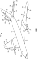
- FIG. 1 is a perspective view of aircraft 10 including wings 12, horizontal stabilizers 14, and fuselage 16. Wings 12 include leading edges 18 and horizontal stabilizers 14 include leading edges 20. Of course, the aircraft could also include vertical stabilizers and the teachings herein are also applicable to them.
- aircraft 10 is of a fixed-wing design.
- Fuselage 16 extends from nose section 22 to tail section 24, with wings 12 fixed to fuselage 16 between nose section 22 and tail section 24.
- Horizontal stabilizers 14 are attached to fuselage 16 on tail section 24.
- Wings 12 and horizontal stabilizers 14 function to create lift and to prevent pitching, respectively, for aircraft 10.
- Wings 12 and horizontal stabilizers 14 include critical suction surfaces, such as upper surfaces 26 of wings 12 and lower surfaces 28 of horizontal stabilizers 14, where flow separation and loss of lift can occur if icing conditions form on any of the surfaces of wings 12 and horizontal stabilizers 14.
- FIG. 1 also shows structures with embedded CNT heating elements 30 mounted onto leading edges 18 of wings 12 and onto leading edges 20 of horizontal stabilizers 14.
- structures with embedded CNT heating elements 30 can be mounted onto any leading edge or non-leading edge surface of aircraft 10. Structures with embedded CNT heating elements 30 function generating heat so as to prevent ice from forming on or shed ice formed on any of the above noted surfaces. Further, it should be noted that the assemblies could be mounted to an engine lip and engine induction deicers generally shown by reference number 31.
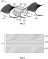
- a multilayer structure 200 that includes a heater mat 202.
- the heater mat is formed as a carbon nano-tube (CNT) heater.
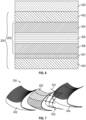
- FIG. 3 shows a more detailed version of the CNT heater 202 of structure of FIG. 2 .
- the CNT heater 202 includes a heating layer 300.
- the heating layer 300 includes at least one sheet of a carbon allotrope material, such as carbon nanotubes (CNT), which have a generally cylindrical structure.
- CNT carbon nanotubes
- a CNT sheet can be formed from CNT suspended in a matrix, a dry CNT fiber, or a CNT yarn, to name a few non-limiting examples.
- the carbon allotrope material of the CNT heater 202 includes graphene, graphene nanoribbons (GNRs), or other suitable carbon allotropes.
- GNRs graphene has a two-dimensional honeycomb lattice structure, and GNRs are strips of graphene with ultrathin widths.
- the heating layer 300 can be a heating assembly that includes several layers.
- the layer 300 can include, for example, the structure as disclosed in U.S. Patent No. 11,167,856 that includes a composite of CNT and silicon surrounded by metal layers.
- the CNT heater 202 also includes first and second (or fore and aft) encapsulation layers 304, 306.
- the encapsulation layers are formed of a thermoplastic material. Examples of such materials include materials that become molten when heated, solid when cooled, and can be re-melted or molded after cooling. The curing process is completely reversible, and doing so will not compromise the material's physical integrity.
- thermoset materials In contrast to the encapsulation layers 304, 306 show in FIG. 3 , using thermoset materials will create irreversible chemical bonds during curing. As such, a thermoset material cannot be melted/reversed, and this current state of the art makes repairing a heater or assembly difficult if not impossible.
- thermoplastic dielectric encapsulation layers 304, 306 examples include, but are not limited to polyether ether ketone (PEEK), thermoplastic polyimide, or Polyaryletherketone (PAEK).
- PEEK polyether ether ketone
- PAEK Polyaryletherketone
- thermoplastic encapsulation layers 304, 306 can be heated and reformed, if there is damage to either them or the heating layer 300, the combination thereof can be heated and separated.
- the composite structures 402, 404 can be formed of a thermoplastic in one embodiment.
- the composite structures 402, 404 are formed of same thermoplastic as thermoplastic encapsulation layers 304, 306.
- the composite structures 402, 404 are formed of a different thermoplastic than thermoplastic encapsulation layers 304, 306.
- encapsulation layers 304, 306 are formed of a thermoplastic that has a higher melting temperature than the composite structures 402, 404.
- the thermoplastic material of the encapsulation layers 304, 306 can be melted so that the material infuses between the carbon nanotubes of the heating layer 300.
- the composite structures 402, 404 are added as described elsewhere herein.
- Such a version may result in smaller heating layer 300 and, thus, reduce the amount of material needed in the full assembly structure which will lead to less power required from the CNT heater for ice protection.
- the heating layer 300 (or CNT layer) thermoplastic material can, thus, be different than one or both of the composite structures 402, 404 thermoplastic materials.
- the encapsulation layers 304, 306 can be formed of PEEK resin and layers 402/404 may be formed of a PAEK resin
- the CNT heater 202 can be provided and then bonded to the composite structures 402, 404 by adding heat. In one embodiment, some or all of the heat can be provided by the CNT heater.
- Embodiments herein may reduce manufacturing complexity/costs and decrease power required from the heater mat during operation. This will also allow for the heater mat to be repaired or replaced instead of having to discard the entire structural component thus decreasing repair and maintenance costs.
- the use of a thermoplastic structure will also provide higher temp limits the heater mat can operate which could decrease design constraints.
- the aft composite structure can directly contact the encapsulation layer 306 in some cases and be separated from (e.g., not in direct contact) it.
- the composite structures 402, 404 can be formed to have a shape such they can be applied to any of the surfaces of an aircraft as shown above.
- the CNT heaters 202 can be formed into a flat or shaped mat and then place on one of the structures 402, 404 and then other of the structures 402, 404 is provided to encapsulate the CNT heater 202.
- the structure so formed can then be heated to at least partially melt them to bond the assembly together.
- a method of forming a structure that includes receiving a carbon nano-tube (CNT) heater as disclosed herein.
- the method can also include receiving a fore composite structure 402 that includes a fore composite structure thermoplastic material and an aft composite structure 404 that includes an aft composite structure thermoplastic material.
- the two structures 402, 404 can be placed on opposing sides of the CNT heater 202. OF course, as shown below, other layers or material could be placed between the CNT heater 202 and the structures 402, 404. Heat can then be applied to bond the assembly together.
- FIG. 5 shows another embodiment of an assembly.
- This assembly includes additional optional layers/elements.
- the elements include sensors located in a sensor layer 501 and the layer includes a low ice adhesion coating layer 520.
- the layer includes a low ice adhesion coating layer 520.
- one embodiment is an assembly 700 that only includes the sensor layer 501 (see FIG. 7 ) and another assembly 800 can include only the low ice adhesion coating layer 520 ( FIG. 8 ).
- the sensor layer 501 includes sensors 502 are between the CNT heater 202 and the back or aft composite structure 404.
- the sensors elements 502 could alternatively be place between the CNT heater 202 and the fore or front composite structure 402.
- the sensors 502 are an array of fiber optic sensors that can detect one or both temperature and stress/strain on the assemblies 500, 600, 700.
- the sensors 502 of the sensor layer 501 can include a plurality of temperature sensors 504 and a plurality strain gauge sensors 506.
- the sensors 504, 506 can be apart of a fiber optic cable 508 in one embodiment.
- Each fiber optic cable 508 can include both types of sensors 504, 506 which reduces the amount of additional wires that are needed to install the different type of sensors.
- the plurality of sensors 504, 506 is apart of each fiber optic cable 508, and the individual readings from sensors 504, 506 on the same fiber optic cable 508 can be processed by, for example, a controller 550 in a variety of ways.
- the controller 550 can process each signal from corresponding sensors 504, 506 using a known time delay or wavelength.
- Each of the sensors 504, 506 can be associated with a particular location of the aircraft for mapping.
- FIG. 5 illustrates a fixed number of sensors, however, it should be understood that any number of sensors and placement of the sensors can be used.
- the arrangement of fiber optic-based sensors is on a surface of a substrate 550, it can be appreciated the sensors can be placed directly on the for or aft composite structure 402, 404.
- the sensor layer includes a substrate 550 that supports the sensors and in another it does not.
- the cables 508 extend in the horizontal direction in FIG. 9 and the vertical direction in FIGs. 5 and 7 to illustrate that either orientation is possible.
- the sensors 504, 506 can be arranged in a manner that they line up with a plurality of zones 210-218 of the heater 202 for monitoring the various zones.
- the zones in the heater 202 are shown in FIG. 2 but can apply to all CNT heaters disclosed herein and the orientation can be vertical or horizontal as shown. Example correspondence to the zones in FIG. 2 is shown in FIG. 9 .
- the low ice adhesion coating layer 520 of FIGs. 5 , 6 and 8 can be any type of coating on which it is difficult for ice to adhere.
- the low ice adhesion coating layer may comprise polydimethylsiloxane (PDMS), at least one of nanoscale amorphous silica and super hydrophobic nanoparticles, and at least one of a non-reactive hydrophobic additive and a non-reactive hydrophilic additive.
- the coating may further comprise fluoride.
- An example of such a layer is more fully described U.S. Patent Application Publication No. US20210179276A1 which is incorporated herein by reference.
- the low ice adhesion coating layer 520 could be an Ice Phobic Material where any water that runs across it does not turn to ice due to the low ice adhesion.
- An example of such a material may have low ice adhesion, at least below 200 psi (pounds per square inch), preferably below 100 psi, and typically below 45 psi.
- Such materials includes multiscale crack initiator promoted super-low ice adhesion surfaces, Slippery Liquid-Infused Nanostructured Surfaces (SLIPS), HygraTek , HybridShield0 by NanoSonic ice phobic coatings, PPG IcePhobic Coating, NANOMYTE SuperAi by NEI Corporation, or other materials/coatings with low ice adhesion.
- SLIPS Slippery Liquid-Infused Nanostructured Surfaces
- HygraTek HybridShield0 by NanoSonic ice phobic coatings
- PPG IcePhobic Coating NANOMYTE SuperAi by NEI Corporation, or other materials/coatings with low ice adhesion.
- the low ice adhesion coating layer 520 can include health monitoring capabilities as well.
Landscapes
- Resistance Heating (AREA)
- Laminated Bodies (AREA)
Applications Claiming Priority (1)
| Application Number | Priority Date | Filing Date | Title |
|---|---|---|---|
| US18/168,133 US20230202661A1 (en) | 2021-10-18 | 2023-02-13 | Multilayer structure with carbon nanotube heaters |
Publications (2)
| Publication Number | Publication Date |
|---|---|
| EP4426055A2 true EP4426055A2 (fr) | 2024-09-04 |
| EP4426055A3 EP4426055A3 (fr) | 2024-09-25 |
Family
ID=89900864
Family Applications (1)
| Application Number | Title | Priority Date | Filing Date |
|---|---|---|---|
| EP24157159.5A Pending EP4426055A3 (fr) | 2023-02-13 | 2024-02-12 | Structure multicouche avec éléments chauffants à nanotubes de carbone |
Country Status (1)
| Country | Link |
|---|---|
| EP (1) | EP4426055A3 (fr) |
Citations (2)
| Publication number | Priority date | Publication date | Assignee | Title |
|---|---|---|---|---|
| US20210179276A1 (en) | 2019-12-12 | 2021-06-17 | Goodrich Corporation | Ice protection system for rotary blades |
| US11167856B2 (en) | 2018-12-13 | 2021-11-09 | Goodrich Corporation Of Charlotte, Nc | Multilayer structure with carbon nanotube heaters |
Family Cites Families (4)
| Publication number | Priority date | Publication date | Assignee | Title |
|---|---|---|---|---|
| GB2453769B (en) * | 2007-10-18 | 2012-09-05 | Gkn Aerospace Services Ltd | An aircraft leading edge thermoplastic heating mat |
| DE102011119844A1 (de) * | 2011-05-26 | 2012-12-13 | Eads Deutschland Gmbh | Verbundstruktur mit Eisschutzvorrichtung sowie Herstellverfahren |
| KR20180089449A (ko) * | 2015-11-30 | 2018-08-08 | 사이텍 인더스트리스 인코포레이티드 | 복합 구조용 표면 재료 |
| EP3406424B1 (fr) * | 2017-05-22 | 2021-04-28 | Ratier-Figeac SAS | Pale d'aéronef et procédés de formation et de réparation d'une pale d'aéronef |
-
2024
- 2024-02-12 EP EP24157159.5A patent/EP4426055A3/fr active Pending
Patent Citations (2)
| Publication number | Priority date | Publication date | Assignee | Title |
|---|---|---|---|---|
| US11167856B2 (en) | 2018-12-13 | 2021-11-09 | Goodrich Corporation Of Charlotte, Nc | Multilayer structure with carbon nanotube heaters |
| US20210179276A1 (en) | 2019-12-12 | 2021-06-17 | Goodrich Corporation | Ice protection system for rotary blades |
Also Published As
| Publication number | Publication date |
|---|---|
| EP4426055A3 (fr) | 2024-09-25 |
Similar Documents
| Publication | Publication Date | Title |
|---|---|---|
| EP3342711B1 (fr) | Système de dégivrage de chaussure pneumatique et électrothermique combiné | |
| CA2786838C (fr) | Systeme de degivrage/antigivrage multifonctionnel | |
| EP4120796B1 (fr) | Répartition uniforme de la chaleur dans les dispositifs de chauffage à résistance de dégivrage et d'antigivrage | |
| EP2523855B1 (fr) | Élément doté d'une fonction de dégivrage/antigivrage | |
| EP3342702B1 (fr) | Bande d'érosion intégrée à des éléments de dégivrage/anti-givrage à base d'allotrope de carbone | |
| US11122649B2 (en) | Electrically heatable layer stack | |
| BR112014002438B1 (pt) | laminado híbrido compósitos de molibdênio e método de formação de um laminado híbrido compósito de molibdênio | |
| US20230202661A1 (en) | Multilayer structure with carbon nanotube heaters | |
| EP4167683A1 (fr) | Système de protection contre la glace intégré | |
| WO2015181516A1 (fr) | Surveillance de santé structurelle améliorée | |
| CN112106441A (zh) | (类型8)加热器垫 | |
| EP3339178B1 (fr) | Matrice de résine conductrice électrique pour chauffage cnt | |
| EP3643617B1 (fr) | Conception d'élément chauffant pour systèmes de protection contre la glace à allotrope en carbone | |
| EP4426055A2 (fr) | Structure multicouche avec éléments chauffants à nanotubes de carbone | |
| EP4167684A1 (fr) | Structure thermoplastique multicouche avec dispositifs de chauffage à nanotubes de carbone | |
| CN115991282A (zh) | 一体式防冰系统 | |
| GB2526569A (en) | Improved structural health monitoring | |
| BR102022020849A2 (pt) | Estrutura de aquecimento multicamada para controlar o acúmulo de gelo em uma superfície de uma aeronave, e, método para formar uma estrutura de aquecimento multicamada para controlar o acúmulo de gelo em uma superfície de uma aeronave | |
| EP3543138B1 (fr) | Installation de dégivreurs pneumatiques comportant des nanotubes de carbone alignés verticalement | |
| EP4289609B1 (fr) | Chauffage de matériau thermoplastique utilisant un ou des dispositifs de chauffage électrique pour système d'antigivrage thermique | |
| US7064302B2 (en) | Electrical connection for a resistor element made of electrically-conductive fibers | |
| CN111319772A (zh) | 用于粘结除冰器的填充有z-cnt的可熔化粘合剂 | |
| CN111152481A (zh) | 在铺叠芯棒上置放电子器件来在复合零件中创建电子器件 | |
| CN111071454B (zh) | 碳同素异形体防冰系统的加热器设计 | |
| EP4724267A1 (fr) | Matériau composite renforcé par des fibres, comprenant des couches de préimprégné de fibres avec des nanotubes de carbone conducteurs ou des couches intermédiaires de nanofibres |
Legal Events
| Date | Code | Title | Description |
|---|---|---|---|
| PUAI | Public reference made under article 153(3) epc to a published international application that has entered the european phase |
Free format text: ORIGINAL CODE: 0009012 |
|
| STAA | Information on the status of an ep patent application or granted ep patent |
Free format text: STATUS: THE APPLICATION HAS BEEN PUBLISHED |
|
| PUAL | Search report despatched |
Free format text: ORIGINAL CODE: 0009013 |
|
| AK | Designated contracting states |
Kind code of ref document: A2 Designated state(s): AL AT BE BG CH CY CZ DE DK EE ES FI FR GB GR HR HU IE IS IT LI LT LU LV MC ME MK MT NL NO PL PT RO RS SE SI SK SM TR |
|
| AK | Designated contracting states |
Kind code of ref document: A3 Designated state(s): AL AT BE BG CH CY CZ DE DK EE ES FI FR GB GR HR HU IE IS IT LI LT LU LV MC ME MK MT NL NO PL PT RO RS SE SI SK SM TR |
|
| RIC1 | Information provided on ipc code assigned before grant |
Ipc: H05B 3/36 20060101ALI20240822BHEP Ipc: H05B 3/14 20060101AFI20240822BHEP |
|
| STAA | Information on the status of an ep patent application or granted ep patent |
Free format text: STATUS: REQUEST FOR EXAMINATION WAS MADE |
|
| 17P | Request for examination filed |
Effective date: 20250317 |