EP4427700A2 - Pointe de cathéter irriguée avec capteur de température et réseaux de fibres optiques - Google Patents
Pointe de cathéter irriguée avec capteur de température et réseaux de fibres optiques Download PDFInfo
- Publication number
- EP4427700A2 EP4427700A2 EP24191176.7A EP24191176A EP4427700A2 EP 4427700 A2 EP4427700 A2 EP 4427700A2 EP 24191176 A EP24191176 A EP 24191176A EP 4427700 A2 EP4427700 A2 EP 4427700A2
- Authority
- EP
- European Patent Office
- Prior art keywords
- tissue
- optical
- cap
- multiplicity
- optical radiation
- Prior art date
- Legal status (The legal status is an assumption and is not a legal conclusion. Google has not performed a legal analysis and makes no representation as to the accuracy of the status listed.)
- Withdrawn
Links
Images



Classifications
-
- A—HUMAN NECESSITIES
- A61—MEDICAL OR VETERINARY SCIENCE; HYGIENE
- A61B—DIAGNOSIS; SURGERY; IDENTIFICATION
- A61B18/00—Surgical instruments, devices or methods for transferring non-mechanical forms of energy to or from the body
- A61B18/04—Surgical instruments, devices or methods for transferring non-mechanical forms of energy to or from the body by heating
- A61B18/12—Surgical instruments, devices or methods for transferring non-mechanical forms of energy to or from the body by heating by passing a current through the tissue to be heated, e.g. high-frequency current
- A61B18/14—Probes or electrodes therefor
- A61B18/1492—Probes or electrodes therefor having a flexible, catheter-like structure, e.g. for heart ablation
-
- A—HUMAN NECESSITIES
- A61—MEDICAL OR VETERINARY SCIENCE; HYGIENE
- A61B—DIAGNOSIS; SURGERY; IDENTIFICATION
- A61B17/00—Surgical instruments, devices or methods
- A61B2017/00017—Electrical control of surgical instruments
- A61B2017/00022—Sensing or detecting at the treatment site
- A61B2017/00057—Light
-
- A—HUMAN NECESSITIES
- A61—MEDICAL OR VETERINARY SCIENCE; HYGIENE
- A61B—DIAGNOSIS; SURGERY; IDENTIFICATION
- A61B18/00—Surgical instruments, devices or methods for transferring non-mechanical forms of energy to or from the body
- A61B2018/00005—Cooling or heating of the probe or tissue immediately surrounding the probe
- A61B2018/00011—Cooling or heating of the probe or tissue immediately surrounding the probe with fluids
- A61B2018/00029—Cooling or heating of the probe or tissue immediately surrounding the probe with fluids open
-
- A—HUMAN NECESSITIES
- A61—MEDICAL OR VETERINARY SCIENCE; HYGIENE
- A61B—DIAGNOSIS; SURGERY; IDENTIFICATION
- A61B18/00—Surgical instruments, devices or methods for transferring non-mechanical forms of energy to or from the body
- A61B2018/00315—Surgical instruments, devices or methods for transferring non-mechanical forms of energy to or from the body for treatment of particular body parts
- A61B2018/00345—Vascular system
- A61B2018/00351—Heart
-
- A—HUMAN NECESSITIES
- A61—MEDICAL OR VETERINARY SCIENCE; HYGIENE
- A61B—DIAGNOSIS; SURGERY; IDENTIFICATION
- A61B18/00—Surgical instruments, devices or methods for transferring non-mechanical forms of energy to or from the body
- A61B2018/00315—Surgical instruments, devices or methods for transferring non-mechanical forms of energy to or from the body for treatment of particular body parts
- A61B2018/00345—Vascular system
- A61B2018/00351—Heart
- A61B2018/00357—Endocardium
-
- A—HUMAN NECESSITIES
- A61—MEDICAL OR VETERINARY SCIENCE; HYGIENE
- A61B—DIAGNOSIS; SURGERY; IDENTIFICATION
- A61B18/00—Surgical instruments, devices or methods for transferring non-mechanical forms of energy to or from the body
- A61B2018/00571—Surgical instruments, devices or methods for transferring non-mechanical forms of energy to or from the body for achieving a particular surgical effect
- A61B2018/00577—Ablation
-
- A—HUMAN NECESSITIES
- A61—MEDICAL OR VETERINARY SCIENCE; HYGIENE
- A61B—DIAGNOSIS; SURGERY; IDENTIFICATION
- A61B18/00—Surgical instruments, devices or methods for transferring non-mechanical forms of energy to or from the body
- A61B2018/00636—Sensing and controlling the application of energy
- A61B2018/00666—Sensing and controlling the application of energy using a threshold value
- A61B2018/00678—Sensing and controlling the application of energy using a threshold value upper
-
- A—HUMAN NECESSITIES
- A61—MEDICAL OR VETERINARY SCIENCE; HYGIENE
- A61B—DIAGNOSIS; SURGERY; IDENTIFICATION
- A61B18/00—Surgical instruments, devices or methods for transferring non-mechanical forms of energy to or from the body
- A61B2018/00636—Sensing and controlling the application of energy
- A61B2018/00696—Controlled or regulated parameters
- A61B2018/00702—Power or energy
-
- A—HUMAN NECESSITIES
- A61—MEDICAL OR VETERINARY SCIENCE; HYGIENE
- A61B—DIAGNOSIS; SURGERY; IDENTIFICATION
- A61B18/00—Surgical instruments, devices or methods for transferring non-mechanical forms of energy to or from the body
- A61B2018/00636—Sensing and controlling the application of energy
- A61B2018/00696—Controlled or regulated parameters
- A61B2018/00744—Fluid flow
-
- A—HUMAN NECESSITIES
- A61—MEDICAL OR VETERINARY SCIENCE; HYGIENE
- A61B—DIAGNOSIS; SURGERY; IDENTIFICATION
- A61B18/00—Surgical instruments, devices or methods for transferring non-mechanical forms of energy to or from the body
- A61B2018/00636—Sensing and controlling the application of energy
- A61B2018/00773—Sensed parameters
- A61B2018/00791—Temperature
-
- A—HUMAN NECESSITIES
- A61—MEDICAL OR VETERINARY SCIENCE; HYGIENE
- A61B—DIAGNOSIS; SURGERY; IDENTIFICATION
- A61B18/00—Surgical instruments, devices or methods for transferring non-mechanical forms of energy to or from the body
- A61B2018/00636—Sensing and controlling the application of energy
- A61B2018/00773—Sensed parameters
- A61B2018/00791—Temperature
- A61B2018/00797—Temperature measured by multiple temperature sensors
-
- A—HUMAN NECESSITIES
- A61—MEDICAL OR VETERINARY SCIENCE; HYGIENE
- A61B—DIAGNOSIS; SURGERY; IDENTIFICATION
- A61B18/00—Surgical instruments, devices or methods for transferring non-mechanical forms of energy to or from the body
- A61B2018/00636—Sensing and controlling the application of energy
- A61B2018/00773—Sensed parameters
- A61B2018/00791—Temperature
- A61B2018/00815—Temperature measured by a thermistor
-
- A—HUMAN NECESSITIES
- A61—MEDICAL OR VETERINARY SCIENCE; HYGIENE
- A61B—DIAGNOSIS; SURGERY; IDENTIFICATION
- A61B18/00—Surgical instruments, devices or methods for transferring non-mechanical forms of energy to or from the body
- A61B2018/00636—Sensing and controlling the application of energy
- A61B2018/00773—Sensed parameters
- A61B2018/00791—Temperature
- A61B2018/00821—Temperature measured by a thermocouple
-
- A—HUMAN NECESSITIES
- A61—MEDICAL OR VETERINARY SCIENCE; HYGIENE
- A61B—DIAGNOSIS; SURGERY; IDENTIFICATION
- A61B90/00—Instruments, implements or accessories specially adapted for surgery or diagnosis and not covered by any of the groups A61B1/00 - A61B50/00, e.g. for luxation treatment or for protecting wound edges
- A61B90/06—Measuring instruments not otherwise provided for
- A61B2090/064—Measuring instruments not otherwise provided for for measuring force, pressure or mechanical tension
- A61B2090/065—Measuring instruments not otherwise provided for for measuring force, pressure or mechanical tension for measuring contact or contact pressure
-
- A—HUMAN NECESSITIES
- A61—MEDICAL OR VETERINARY SCIENCE; HYGIENE
- A61B—DIAGNOSIS; SURGERY; IDENTIFICATION
- A61B2218/00—Details of surgical instruments, devices or methods for transferring non-mechanical forms of energy to or from the body
- A61B2218/001—Details of surgical instruments, devices or methods for transferring non-mechanical forms of energy to or from the body having means for irrigation and/or aspiration of substances to and/or from the surgical site
- A61B2218/002—Irrigation
Definitions
- the present invention relates generally to invasive medical devices, and particularly to probes used in ablating tissue within the body.
- Minimally-invasive intracardiac ablation is the treatment of choice for various types of arrhythmias.
- the physician typically inserts a catheter through the vascular system into the heart, brings the distal end of the catheter into contact with myocardial tissue in areas of abnormal electrical activity, and then energizes one or more electrodes at or near the distal end in order to create tissue necrosis.
- Biosense Webster Inc. offers the ThermoCool ® irrigated-tip catheter for use with its CARTO ® integrated mapping and ablation system.
- the metal catheter tip which is energized with radio-frequency (RF) electrical current to ablate the tissue, has a number of peripheral holes, distributed circumferentially around the tip, for irrigation of the treatment site.
- RF radio-frequency
- U.S. Patent Application Publication 2010/0030209 describes a catheter with a perforated tip, which includes an insertion tube, having a distal end for insertion into a body of a subject.
- a distal tip is fixed to the distal end of the insertion tube and is coupled to apply energy to tissue inside the body.
- the distal tip has an outer surface with a plurality of perforations through the outer surface, which are distributed circumferentially and longitudinally over the distal tip.
- a lumen passes through the insertion tube and is coupled to deliver a fluid to the tissue via the perforations.
- Some ablation catheters include sensors for monitoring temperature during the ablation procedure.
- U.S. Patent 5,957,961 whose disclosure is incorporated herein by reference, describes a catheter having a distal segment carrying at least one electrode extending along the segment and having a number of temperature sensors arranged along the distal segment adjacent the electrode, each providing an output indicative of temperature.
- the catheter is coupled to a power source, which provides RF energy to the electrode.
- Temperature processing circuitry is coupled to the temperature sensors and the power source, and controls power output from the power source as a function of the outputs of the temperature sensors.
- U.S. Patent 6,312,425 whose disclosure is incorporated herein by reference, describes an RF ablation catheter tip electrode with multiple thermal sensors.
- a tip thermal sensor is located at or near the apex of the distal-end region, and one or more side thermal sensors are located near the surface of the proximal-end region.
- the electrode is preferably an assembly formed from a hollow dome-shaped shell with a core disposed within the shell.
- the side thermal sensor wires are electrically connected inside the shell and the core has a longitudinal channel for the side thermal sensor wires welded to the shell.
- the shell also preferably has a pocket in the apex of the shell, and the end thermal sensor wires pass through the core to the apex of the shell.
- U.S. Patent 6,391,024 whose disclosure is incorporated herein by reference, describes a method of assessing the adequacy of contact between an ablation electrode and biological tissue. The method measures the impedance between an ablation electrode and a reference electrode at a first and second frequencies. A percentage difference between the first-frequency impedance and the second-frequency impedance is stated to provide an indication of the state of electrode/tissue contact.
- U.S. Patent 6,730,077 whose disclosure is incorporated herein by reference, describes a cryocatheter for treatment of tissue.
- a signal conductor extends through the catheter to the catheter tip and connects to a thermally and electrically conductive shell or cap that applies an RF current to the region of tissue contacted by the tip.
- a tissue impedance path between the signal lead and a surface electrode mounted on the patient's skin is monitored to develop a quantitative measure of tissue contact at the distal tip,
- An embodiment of the present invention provides apparatus, consisting of:
- the apparatus typically includes a plurality of temperature sensors, which are mounted within the conductive cap in thermal communication with the outer surface.
- the outer surface is penetrated by multiple apertures, and the conductive cap defines an inner cavity in fluid communication with the lumen of the insertion tube so as to permit irrigation fluid from the lumen to flow out of the cap through the apertures.
- the cap may have a side wall having a multiplicity of longitudinal bores therein, and the fiber optics are inserted into the bores.
- the apparatus may also have a multiplicity of windows, transparent to the optical radiation, located in the outer surface of the cap and connected to respective longitudinal bores so as to seal the bores from penetration of fluid into the bores.
- at least one of the windows is formed from at least one of a transparent epoxy and a glue.
- the apparatus may include a scattering agent mixed with at least one of the windows.
- at least one of the windows is formed from at least one of optical grade flat material and optical grade lensed material.
- a given optical fiber selected from the multiplicity of optical fibers consists of a single optical fiber.
- a given optical fiber selected from the multiplicity of optical fibers consists of an optical fiber bundle.
- the apparatus has an optical module configured to determine contact of the conductive cap with the tissue in response to measuring a first level of the optical radiation conveyed via a given optical fiber to the tissue and a second level of the optical radiation conveyed via the given optical fiber from the tissue.
- the apparatus includes an optical module configured to determine a characteristic of the tissue in response to measuring a first level of the optical radiation conveyed via a first optical fiber to the tissue and a second level of the optical radiation conveyed via a second optical fiber from the tissue.
- the characteristic includes a wall thickness of the tissue.
- the apparatus includes a power generator, coupled to provide the electrical energy to the conductive cap so as to ablate the tissue, and an optical module configured to determine a change in a level of the optical radiation while the tissue is ablating.
- a method including:
- Intracardiac ablation procedures are characterized by rapid temperature changes and non-uniform temperature distribution in the tissue and its vicinity. Therefore, the temperature measured by a sensor at the tip of an ablation catheter may not accurately reflect the actual, current temperature in the tissue. Furthermore, when a temperature sensor in a catheter is washed by irrigation fluid, the temperature reading will reflect the fluid temperature, which is generally far cooler than the tissue temperature outside the catheter.
- Some embodiments of the present invention that are described hereinbelow provide irrigated ablation electrodes with embedded temperature sensors that provide accurate tissue temperature assessment.
- Such electrodes typically comprise a conductive cap, which is attached to the distal tip of the insertion tube of an invasive probe, such as a cardiac catheter.
- a cooling fluid flows out through an array of perforations in the electrode to irrigate the tissue under treatment.
- the temperature sensors are mounted at different locations in proximity to the outer surface of the electrode.
- the electrode is constructed so that the sensors are in proximity to and thermal communication with the outer surface, and are thermally insulated from, rather than immersed in, the cooling fluid within the probe.
- the sensors thus provide multiple temperature readings that are substantially independent of the cooling fluid temperature, at different locations on the tip electrode.
- the sensor that gives the highest temperature reading is the one that is in contact with the tissue being ablated, and the temperature measured by this sensor varies linearly with the actual tissue temperature. (Flow of the cooling fluid through the perforations in the electrode is generally lowest in areas that are in firm contact with the tissue, and the sensors in these areas typically give the highest temperature readings.) The reading from this hottest sensor may thus be used in particular to monitor the tissue temperature and control the applied power and duration of the ablation procedure in order to obtain the desired therapeutic result without excessive tissue damage. Alternatively or additionally, the temperature readings of the multiple sensors can be combined and interpolated to give a map of temperature over the area of the catheter tip.
- Some embodiments of the present invention incorporate a multiplicity of optical fibers terminating in proximity to the outer surface of the conductive cap.
- the optical fibers may transmit optical radiation to the tissue being ablated, and also receive returning optical radiation from the tissue. Measurements of levels of returning radiation at all or some of the fiber optics enable embodiments of the present invention to determine if the conductive cap is in contact with the tissue, as well as to characterize the tissue being irradiated by the radiation.
- Fig. 1 is a schematic pictorial illustration of a system 20 for cardiac ablation treatment, in accordance with an embodiment of the present invention.
- An operator 28 inserts a catheter 22 via the vascular system of a patient 26 into a chamber of the patient's heart 24.
- the operator may advance the catheter into the left atrium and bring a distal end 30 of the catheter into contact with myocardial tissue that is to be monitored and/or ablated.
- Catheter 22 is connected at its proximal end to a console 32, which is controlled by operator 28 to apply and monitor the desired treatment.
- Console 32 comprises an RF energy generator 34, which supplies electrical power via catheter 22 to distal end 30 in order to ablate the target tissue.
- Monitoring circuitry 36 tracks the temperature of the tissue at distal end 30 by processing the outputs of temperature sensors in the distal end, as described below.
- An irrigation pump 38 supplies a cooling fluid, such as saline solution, through catheter 22 to irrigate distal end 30.
- an optical module 40 provides optical radiation, typically from, but not limited to, a laser, an incandescent lamp, an arc lamp, or a light emitting diode (LED), for transmission from distal end 30 to the target tissue. The module receives and analyzes optical radiation returning from the target tissue and acquired at the distal end, as described below.
- console 32 may control the power applied by RF energy generator 34 and/or the flow of fluid provided by pump 38, either automatically or in response to inputs by operator 28.
- System 20 may be based on the above-mentioned CARTO system, for example, which provides extensive facilities to support navigation and control of catheter 22. These system facilities, however, including details of the monitoring and control functions of monitoring circuitry 36 and console 32 generally, are beyond the scope of the present patent application.
- Figs. 2A and 2B schematically illustrate distal end 30 of catheter 22, in accordance with an embodiment of the present invention.
- Fig. 2A is a sectional view along the length of the catheter
- Fig. 2B is a cross-sectional view along the cut IIB-IIB that is marked in Fig. 2A .
- An insertion tube 42 extends along the length of the catheter and is connected at its distal end to a conductive cap 44.
- insertion tube 42 comprises a flexible, biocompatible polymer
- cap 44 comprises a biocompatible metal suitable to serve as an ablation electrode, such as gold or platinum, for example.
- Cap 44 is perforated by an array of irrigation apertures 46, which is open from the outer surface of the cap into an inner cavity 58 within the cap.
- Temperature sensors 48 are mounted within conductive cap 44 at locations that are arrayed around the distal tip of the catheter, both axially and circumferentially.
- cap 44 contains six sensors, with one group in a distal location, close to the tip, and the other group in a slightly more proximal location. This distribution is shown only by way of example, however, and greater or smaller numbers of sensors may be mounted in any suitable locations within the cap.
- Sensors 48 may comprise thermocouples, thermistors, or any other suitable type of miniature temperature sensor. These sensors are connected by leads 52 running through the length of insertion tube 42 to provide temperature signals to monitoring circuitry 36.
- Temperature sensors 48 are mounted within ribs 50 inside cap 44.
- the ribs are typically an integral part of cap 44 and may be made from the same material as the outer surface of the cap or from some other suitable type of metal, which is physically and thermally bonded to the cap.
- the diameter of the ribs may be a few tenths of a millimeter in the present example.
- the integral construction of ribs 50 with cap 44 causes sensors 48 to be in thermal communication with the outer surface of the cap, i.e., the temperature inside ribs 50 closely tracks the temperature of the outer surface.
- the ribs are thick enough to thermally insulate these sensors from the irrigation fluid in cavity 58. As a result, temperature sensors 48 measure the true temperature of the outer surface of cap 44, which most accurately reflects the temperature of the tissue with which the cap is in contact.
- distal end 30 contains other functional components, which are outside the scope of the present disclosure and are therefore omitted for the sake of simplicity.
- the distal end of the catheter may contain steering wires, as well as sensors of other types, such as a position sensor and/or a contact force sensor.
- sensors of these sorts is described, for example, in U.S. Patent Application Publication 2009/0138007 , whose disclosure is incorporated herein by reference.
- Fig. 3 is a schematic sectional view of distal end 30, in accordance with another embodiment of the present invention. Elements of this embodiment that are similar to corresponding elements in the embodiment of Figs. 2A and 2B are marked with the same indicator numbers.
- a conductive, perforated cap 64 attached to the distal end of insertion tube 42, is designed to have very low thermal capacity, and sensors 48 are held in contact with cap 64.
- the temperature of cap 64 more closely track changes in the actual tissue temperature, and sensors 48 more closely track the temperature of the outer surface of cap 64. Sensors 48 thus provide a more accurate, timely indication of changes in the temperature of the tissue with which cap 64 is in contact.
- cap 64 contains an inner wall 60, which is not perforated, in close proximity and parallel to the cap.
- Lumen 54 supplies irrigation fluid to a cavity 66 that is formed between cap 64 and wall 60, and the irrigation fluid exits this cavity through apertures 46 in cap 64.
- cap 64 and wall comprise thin shells of metallic material and are held apart by small metallic spacers 62, around which the fluid is able to flow within cavity 66. These spacers may be distributed within cap in any suitable arrangement, for example in pairs (like the pair shown in Fig. 3 ) of axially-spaced sensors at different circumferential locations.
- Spacers 62 also hold temperature sensors 48 in thermal communication with the outer surface of cap 64, while insulating the sensors from the surrounding irrigation fluid in cavity 66. Even without the insulating effect of spacers 62, the effect of the irrigation fluid temperature on sensors 48 in this embodiment is minimal due to the small volume of cavity 66 (relative to cavity 58 in the preceding embodiment, for example).
- cap 64 In a configuration suitable for intracardiac ablation, cap 64 has an outer diameter of about 2.5 mm and a similar length. The thickness of both cap 64 and wall 60 is about 100 um, while apertures 46 have a diameter in the range of 25-100 um. Although cap 64 and wall 60 are very thin, the mechanical integrity of the entire structure is maintained by connecting the cap and wall together with spacers 62.
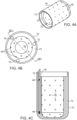
- FIGs. 4A-4C schematically illustrate a catheter cap 70, in accordance with yet another embodiment of the present invention.
- Cap 70 may be used at distal end 30 of catheter 22 in place of the caps shown in the preceding embodiments.
- Fig. 4A is a schematic, pictorial illustration of cap 70
- Fig. 4B is a schematic end view showing the interior of the cap
- Fig. 4C is a sectional view taken along the line IVC-IVC in Fig. 4B .
- Cap 70 comprises a side wall 74 that is relatively thick, on the order of 0.4 mm thick, in order to provide the desired thermal insulation between temperature sensors 48 and the irrigation fluid inside a central cavity 76 of the tip. As in the preceding embodiments, the irrigation fluid exits cavity 76 through apertures 46.
- Sensors 48 are mounted in hollow tubes 78, which are filled with a suitable glue, such as epoxy and fitted into longitudinal bores 72 in side wall 74. Tubes 78 may comprise a suitable plastic material, such as polyimide, and may be held in place by a suitable glue, such as epoxy. This arrangement provides an array of six sensors 48 as in the preceding embodiments, with possible advantages of greater ease of manufacture and durability.
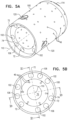
- Figs. 5A-5D schematically illustrate a catheter cap 100
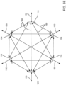
- Fig. 5E schematically illustrates paths taken by light to/from windows in the cap, in accordance with an alternative embodiment of the present invention.
- the operation of cap 100 is generally similar to that of cap 70 ( Figs. 4A, 4B, and 4C ), and elements indicated by the same reference numerals in both caps 70 and 100 are generally similar in construction and in operation.
- Fig. 5A is a schematic, perspective illustration of cap 100
- Fig. 5B is a schematic end view showing the interior of the cap
- Fig. 5C is a schematic sectional view taken along the line VC-VC in Fig. 5B
- Fig. 5D is a schematic sectional view taken along the line VD-VD in Fig. 5B .
- cap 100 In addition to the three longitudinal bores 72 described above for cap 70, wherein sensors 48 mounted in tubes 78 are fitted, in cap 100 three through longitudinal bores 102, and three blind longitudinal bores 106 are formed in side wall 74. As is illustrated in Fig. 5B , the three sets of bores 72, 102, and 106 may be distributed symmetrically around an axis 110 of cap 100. However, the bores are not necessarily distributed symmetrically around axis 110.
- Each through longitudinal bore 102 terminates in a an opening 114 in the outer surface of wall 74, and a transparent window 116 is placed in the opening.
- a fiber optic 118 is inserted into each of the through bores.
- a fiber optic 128 is inserted into each of the blind bores.
- Windows 116 and 124 act as seals preventing fluid external to the outer surface of cap 70 from penetrating into the bores containing the fiber optics.
- Windows 116 and 124 may be formed by filling openings 114 and 120 with an optically transparent glue or epoxy.
- the material of the windows may be filled with a scattering agent to diffuse light passing through the windows.
- the windows may be formed from an optical quality flat or lensed material, and may be secured to their openings with glue.
- each fiber optic 118 or each fiber optic 128 is a single fiber optic, typically having a diameter of approximately 175 pm.
- each fiber optic 118 or each fiber optic 128 comprises a bundle of substantially similar fiber optics, typically having a bundle diameter also of approximately 175 ⁇ m. Implementing the fiber optics as bundles increases the flexibility of cap 100 with respect to more proximal regions of catheter 22.
- cap 100 is connected to the more proximal regions of the catheter by a spring whose deflections are measured for the purpose of measuring a force on the cap, since the increased flexibility means there is little or no change in the spring deflection for a given force.
- a spring which may be used to join the cap 100 to the more proximal regions of the catheter is described in U. S. Patent Application 12/627,327, to Beeckler et al. , whose disclosure is incorporated herein by reference.
- Optical module 40 is configured to be able to provide optical radiation to any one of fiber optics 118 and 128, for transmission from any of the associated windows 116 and 124 so as to irradiate tissue in proximity to cap 100. Simultaneously, the module is able to acquire, via any or all of the windows, radiation returning from the irradiated tissue.
- the array of windows 116 and 124, and their associated fiber optics enables embodiments of the present invention to employ a number of different methods, using optical radiation, for determining characteristics of the irradiated tissue, as well as the proximity of cap 100, or a region of the cap, with respect to the tissue.
- three such methods are described below, but those having ordinary skill in the art will be aware of other methods, and all such methods are included within the scope of the present invention.
- a first method detects contact of any one of windows 116 or 124, and consequently of the catheter, with tissue.
- Optical radiation of a known intensity, is transmitted through each fiber optic, so as to exit from the optic's window.
- the intensity of the radiation returning to the window is measured while cap 100 is not in contact with tissue, typically while the cap is in the blood of heart 24.
- Optical monitor 40 may use these intensities as reference values of the optical radiation. For any given window, a change in the value from the window's reference value, as measured by the module, may be taken to indicate that the window is in contact with tissue.
- a second method measures characteristics of tissue being irradiated by the optical radiation. As illustrated in Fig. 5E , for all six windows 116, 124 there are a total of 21 different paths, comprising 6 paths 150 where radiation from a given window returns to that window, and 15 paths 160 where radiation from a given window returns to a different window.
- the change of optical radiation for a given path or group of paths depends on characteristics of tissue in the path or group of paths, so that measurements of the change in all of the paths provide information related to characteristics of the tissue in proximity to cap 100.
- the change in all of the paths may be measured by sequentially transmitting, in a time multiplexed manner, optical radiation from each of windows 116 and 124, and measuring the returning radiation.
- a first transmission from a first window in such a sequence provides values for five paths 160 plus a return path 150 to the first window
- a second transmission from a second window provides values for four new paths 160 plus a return path 150 to the second window
- a fifth transmission from a fifth window provides values for two new paths (a path 160 to the sixth window, and a return path 150 to the fifth window).
- a sixth and final transmission from a sixth window provides one return path 150 through the sixth window.
- Optical module 40 may measure the changes of all the paths, and, typically using a calibration procedure, may derive from the changes optical characteristics of tissue within the paths. Such characteristics may include an overall level of ablation of tissue, or an amount and/or type of necrotic tissue, in the paths.
- a third method uses changes of levels of optical radiation returning to windows 116 and/or 124, such as are described in the two methods, to make an estimate of the wall thickness of tissue being illuminated by the optical radiation.
- temperature sensors 48 may not be installed in wall 74, and only fiber optics 118 are incorporated into the wall. Such an embodiment enables determination of tissue contact with the cap, and/or characterization of the tissue in proximity to the cap, by methods described above.
Landscapes
- Health & Medical Sciences (AREA)
- Life Sciences & Earth Sciences (AREA)
- Surgery (AREA)
- Engineering & Computer Science (AREA)
- Plasma & Fusion (AREA)
- General Health & Medical Sciences (AREA)
- Otolaryngology (AREA)
- Physics & Mathematics (AREA)
- Veterinary Medicine (AREA)
- Biomedical Technology (AREA)
- Heart & Thoracic Surgery (AREA)
- Medical Informatics (AREA)
- Molecular Biology (AREA)
- Animal Behavior & Ethology (AREA)
- Nuclear Medicine, Radiotherapy & Molecular Imaging (AREA)
- Public Health (AREA)
- Cardiology (AREA)
- Surgical Instruments (AREA)
Applications Claiming Priority (3)
| Application Number | Priority Date | Filing Date | Title |
|---|---|---|---|
| US14/090,614 US20140171936A1 (en) | 2012-12-17 | 2013-11-26 | Irrigated catheter tip with temperature sensor and optic fiber arrays |
| EP14194536.0A EP2875791B1 (fr) | 2013-11-26 | 2014-11-24 | Pointe de cathéter irriguée avec capteurs de température et réseaux de fibre optique |
| EP19217989.3A EP3656328B1 (fr) | 2013-11-26 | 2014-11-24 | Pointe de cathéter irriguée avec capteur de température et réseaux de fibre optique |
Related Parent Applications (2)
| Application Number | Title | Priority Date | Filing Date |
|---|---|---|---|
| EP14194536.0A Division EP2875791B1 (fr) | 2013-11-26 | 2014-11-24 | Pointe de cathéter irriguée avec capteurs de température et réseaux de fibre optique |
| EP19217989.3A Division EP3656328B1 (fr) | 2013-11-26 | 2014-11-24 | Pointe de cathéter irriguée avec capteur de température et réseaux de fibre optique |
Publications (2)
| Publication Number | Publication Date |
|---|---|
| EP4427700A2 true EP4427700A2 (fr) | 2024-09-11 |
| EP4427700A3 EP4427700A3 (fr) | 2024-12-04 |
Family
ID=52100996
Family Applications (3)
| Application Number | Title | Priority Date | Filing Date |
|---|---|---|---|
| EP14194536.0A Active EP2875791B1 (fr) | 2013-11-26 | 2014-11-24 | Pointe de cathéter irriguée avec capteurs de température et réseaux de fibre optique |
| EP19217989.3A Active EP3656328B1 (fr) | 2013-11-26 | 2014-11-24 | Pointe de cathéter irriguée avec capteur de température et réseaux de fibre optique |
| EP24191176.7A Withdrawn EP4427700A3 (fr) | 2013-11-26 | 2014-11-24 | Pointe de cathéter irriguée avec capteur de température et réseaux de fibres optiques |
Family Applications Before (2)
| Application Number | Title | Priority Date | Filing Date |
|---|---|---|---|
| EP14194536.0A Active EP2875791B1 (fr) | 2013-11-26 | 2014-11-24 | Pointe de cathéter irriguée avec capteurs de température et réseaux de fibre optique |
| EP19217989.3A Active EP3656328B1 (fr) | 2013-11-26 | 2014-11-24 | Pointe de cathéter irriguée avec capteur de température et réseaux de fibre optique |
Country Status (7)
| Country | Link |
|---|---|
| US (1) | US20140171936A1 (fr) |
| EP (3) | EP2875791B1 (fr) |
| JP (2) | JP6548894B2 (fr) |
| CN (1) | CN104665926A (fr) |
| AU (2) | AU2014268146A1 (fr) |
| CA (1) | CA2872126A1 (fr) |
| IL (1) | IL235636B (fr) |
Families Citing this family (52)
| Publication number | Priority date | Publication date | Assignee | Title |
|---|---|---|---|---|
| US10314650B2 (en) | 2010-06-16 | 2019-06-11 | Biosense Webster (Israel) Ltd. | Spectral sensing of ablation |
| US11490957B2 (en) | 2010-06-16 | 2022-11-08 | Biosense Webster (Israel) Ltd. | Spectral sensing of ablation |
| US10405920B2 (en) * | 2016-01-25 | 2019-09-10 | Biosense Webster (Israel) Ltd. | Temperature controlled short duration ablation |
| ES2727868T3 (es) | 2011-09-22 | 2019-10-21 | Univ George Washington | Sistemas para visualizar el tejido ablacionado |
| CN104066368B (zh) | 2011-09-22 | 2017-02-22 | 乔治华盛顿大学 | 用于使经消融组织可视化的系统和方法 |
| CA2856732A1 (fr) | 2011-12-09 | 2013-06-13 | Metavention, Inc. | Neuromodulation therapeutique du systeme hepatique |
| US20150111918A1 (en) | 2012-03-08 | 2015-04-23 | Medtronic Ardian Luxembourg S.a.r.l | Immune system neuromodulation and associated systems and methods |
| CA2913346A1 (fr) | 2013-06-05 | 2014-12-11 | Metavention, Inc. | Modulation de fibres nerveuses ciblees |
| JP6737705B2 (ja) | 2013-11-14 | 2020-08-12 | ザ・ジョージ・ワシントン・ユニバーシティThe George Washingtonuniversity | 損傷部位の深さを決定するシステムの動作方法及び心臓組織の画像を生成するシステム |
| US20150141847A1 (en) | 2013-11-20 | 2015-05-21 | The George Washington University | Systems and methods for hyperspectral analysis of cardiac tissue |
| US10161924B2 (en) | 2014-03-24 | 2018-12-25 | National Technology & Engineering Solutions Of Sandia, Llc | Sensor system that uses embedded optical fibers |
| US9675416B2 (en) | 2014-04-28 | 2017-06-13 | Biosense Webster (Israel) Ltd. | Prevention of steam pops during ablation |
| US20160081555A1 (en) * | 2014-09-18 | 2016-03-24 | Biosense Webster (Israel) Ltd. | Multi-range optical sensing |
| JP6771731B2 (ja) | 2014-11-03 | 2020-10-21 | 460メディカル・インコーポレイテッド460Medical, Inc. | 接触性評価システム及び方法 |
| EP3215002B1 (fr) | 2014-11-03 | 2024-03-20 | The George Washington University | Systèmes d'évaluation de lésion |
| WO2016081650A1 (fr) | 2014-11-19 | 2016-05-26 | Advanced Cardiac Therapeutics, Inc. | Dispositifs d'ablation, systèmes et procédés d'utilisation d'ensemble électrode à haute résolution |
| EP3220844B1 (fr) | 2014-11-19 | 2020-11-11 | EPiX Therapeutics, Inc. | Systèmes de cartographie à haute résolution de tissu |
| WO2016081611A1 (fr) | 2014-11-19 | 2016-05-26 | Advanced Cardiac Therapeutics, Inc. | Cartographie haute résolution de tissus avec stimulation cardiaque |
| EP3226795B1 (fr) | 2014-12-03 | 2020-08-26 | Metavention, Inc. | Systèmes de modulation de nerfs ou d'autres tissus |
| AU2015268674A1 (en) | 2014-12-29 | 2016-07-14 | Biosense Webster (Israel) Ltd. | Spectral sensing of ablation |
| US9636164B2 (en) | 2015-03-25 | 2017-05-02 | Advanced Cardiac Therapeutics, Inc. | Contact sensing systems and methods |
| CN107427323B (zh) | 2015-03-31 | 2021-02-02 | 圣犹达医疗用品心脏病学部门有限公司 | 高热敏性消融导管和导管尖端 |
| CN107750146A (zh) * | 2015-06-29 | 2018-03-02 | 波士顿科学医学有限公司 | 开放冲洗消融导管 |
| US10779904B2 (en) | 2015-07-19 | 2020-09-22 | 460Medical, Inc. | Systems and methods for lesion formation and assessment |
| US10194981B2 (en) * | 2015-07-29 | 2019-02-05 | Medlumics S.L. | Radiofrequency ablation catheter with optical tissue evaluation |
| US10327859B2 (en) | 2015-09-21 | 2019-06-25 | Biosense Webster (Israel) Ltd. | Catheter stability indication |
| US10213253B2 (en) | 2015-12-24 | 2019-02-26 | Biosense Webster (Israel) Ltd. | Estimating a temperature during ablation |
| US10575901B2 (en) | 2015-12-24 | 2020-03-03 | Biosense Webster (Israel) Ltd. | Estimating a temperature during ablation |
| SG11201807618QA (en) | 2016-03-15 | 2018-10-30 | Epix Therapeutics Inc | Improved devices, systems and methods for irrigated ablation |
| US10524859B2 (en) | 2016-06-07 | 2020-01-07 | Metavention, Inc. | Therapeutic tissue modulation devices and methods |
| CN109788982B (zh) * | 2016-10-04 | 2021-11-02 | 圣犹达医疗用品心脏病学部门有限公司 | 消融导管尖端 |
| IL255845B (en) | 2016-12-20 | 2021-01-31 | Biosense Webster Israel Ltd | Temperature estimation during ablation |
| US11278350B2 (en) | 2017-02-10 | 2022-03-22 | Biosense Webster (Israel) Ltd. | Estimation of tissue thickness |
| US11185366B2 (en) * | 2017-03-14 | 2021-11-30 | Biosense Webster (Israel) Ltd. | Estimation of tissue thickness from rate of change of catheter temperature |
| EP3614946B1 (fr) | 2017-04-27 | 2024-03-20 | EPiX Therapeutics, Inc. | Détermination de la nature d'un contact entre une pointe de cathéter et un tissu |
| US20190117298A1 (en) * | 2017-10-25 | 2019-04-25 | Biosense Webster (Israel) Ltd. | Catheter with improved temperature response |
| US11054315B2 (en) * | 2018-01-10 | 2021-07-06 | Biosense Webster (Israel) Ltd. | Thermally isolated thermocouple |
| US10876902B2 (en) | 2018-01-10 | 2020-12-29 | Biosense Webster (Israel) Ltd. | Position-controlled thermocouple |
| EP3563786A1 (fr) * | 2018-05-04 | 2019-11-06 | VascoMed GmbH | Tête de cathéter, cathéter et procédé de fabrication |
| ES3056750T3 (en) | 2018-05-30 | 2026-02-24 | Avent Inc | System for generating lesions of a certain size by controlling energy delivered and pump flow rate |
| US12144539B2 (en) | 2018-05-30 | 2024-11-19 | Avent, Inc. | Varying the length of a temperature sensing element of a radiofrequency probe based on desired lesion size |
| ES3015689T3 (en) | 2018-05-30 | 2025-05-07 | Avent Inc | Medical probe assembly for mitigating rising impedance via a pump assembly during use of cooled radiofrequency probes |
| US12582463B2 (en) * | 2019-04-10 | 2026-03-24 | St. Jude Medical International Holding S.À R.L. | Ablation catheter tip with flexible electronic circuitry |
| US11172984B2 (en) | 2019-05-03 | 2021-11-16 | Biosense Webster (Israel) Ltd. | Device, system and method to ablate cardiac tissue |
| US11937882B2 (en) * | 2019-08-27 | 2024-03-26 | Biosense Webster (Israel) Ltd. | ENT tools |
| US12076081B2 (en) | 2020-01-08 | 2024-09-03 | 460Medical, Inc. | Systems and methods for optical interrogation of ablation lesions |
| EP4090231A1 (fr) | 2020-01-13 | 2022-11-23 | Medlumics S.L. | Système d'ablation à guidage optique destiné à être utilisé avec une source d'énergie à champ pulsé |
| EP4090228B1 (fr) * | 2020-01-13 | 2023-10-25 | Medlumics S.L. | Procédés, dispositifs et structures de support pour assembler des fibres optiques dans des pointes de cathéter |
| EP4090232A1 (fr) | 2020-01-13 | 2022-11-23 | Medlumics S.L. | Systèmes d'analyse optique et de prédiction de lésion à l'aide de cathéters d'ablation |
| US11331142B2 (en) | 2020-01-13 | 2022-05-17 | Medlumics S.L. | Methods, devices, and support structures for assembling optical fibers in catheter tips |
| WO2021243061A1 (fr) | 2020-05-27 | 2021-12-02 | The George Washington University | Visualisation de lésions par une approche à deux longueurs d'onde |
| CA3150572A1 (fr) | 2021-03-04 | 2022-09-04 | Medlumics S.L. | Methodes, dispositifs et structures de support pour assembler des fibres optiques dans des pointes de catheter |
Citations (7)
| Publication number | Priority date | Publication date | Assignee | Title |
|---|---|---|---|---|
| US5957961A (en) | 1996-03-11 | 1999-09-28 | Medtronic, Inc. | Multiple sensor, temperature controlled R-F ablation system |
| US6217574B1 (en) | 1998-12-03 | 2001-04-17 | Cordis Webster | System and method for measuring subsurface temperature of tissue during ablation |
| US6312425B1 (en) | 1998-05-05 | 2001-11-06 | Cardiac Pacemakers, Inc. | RF ablation catheter tip electrode with multiple thermal sensors |
| US6391024B1 (en) | 1999-06-17 | 2002-05-21 | Cardiac Pacemakers, Inc. | RF ablation apparatus and method having electrode/tissue contact assessment scheme and electrocardiogram filtering |
| US6730077B2 (en) | 1999-09-10 | 2004-05-04 | Cryocath Technologies Inc. | Catheter system |
| US20090138007A1 (en) | 2007-10-08 | 2009-05-28 | Assaf Govari | High-sensitivity pressure-sensing probe |
| US20100030209A1 (en) | 2008-07-15 | 2010-02-04 | Assaf Govari | Catheter with perforated tip |
Family Cites Families (17)
| Publication number | Priority date | Publication date | Assignee | Title |
|---|---|---|---|---|
| AU6139199A (en) * | 1998-09-11 | 2000-04-03 | Spectrx, Inc. | Multi-modal optical tissue diagnostic system |
| US6660001B2 (en) * | 2000-01-21 | 2003-12-09 | Providence Health System-Oregon | Myocardial revascularization-optical reflectance catheter and method |
| US20060229515A1 (en) * | 2004-11-17 | 2006-10-12 | The Regents Of The University Of California | Fiber optic evaluation of tissue modification |
| US9468500B2 (en) * | 2005-04-26 | 2016-10-18 | Tea Time Partners, L.P. | Image-guided laser catheter |
| JP4838029B2 (ja) * | 2006-03-30 | 2011-12-14 | テルモ株式会社 | 画像診断装置およびその処理方法 |
| US7662152B2 (en) * | 2006-06-13 | 2010-02-16 | Biosense Webster, Inc. | Catheter with multi port tip for optical lesion evaluation |
| US8986298B2 (en) * | 2006-11-17 | 2015-03-24 | Biosense Webster, Inc. | Catheter with omni-directional optical tip having isolated optical paths |
| US8577447B2 (en) * | 2007-05-01 | 2013-11-05 | St. Jude Medical, Atrial Fibrillation Division, Inc. | Optic-based contact sensing assembly and system |
| US7976537B2 (en) * | 2007-06-28 | 2011-07-12 | Biosense Webster, Inc. | Optical pyrometric catheter for tissue temperature monitoring during cardiac ablation |
| US8123745B2 (en) * | 2007-06-29 | 2012-02-28 | Biosense Webster, Inc. | Ablation catheter with optically transparent, electrically conductive tip |
| US20090156921A1 (en) * | 2007-12-18 | 2009-06-18 | Huisun Wang | Cardiac ablation catheter with oxygen saturation sensor |
| WO2009090588A1 (fr) * | 2008-01-15 | 2009-07-23 | Koninklijke Philips Electronics N.V. | Appareil, procédé et programme informatique pour appliquer de l'énergie à un objet |
| US20100041986A1 (en) * | 2008-07-23 | 2010-02-18 | Tho Hoang Nguyen | Ablation and monitoring system including a fiber optic imaging catheter and an optical coherence tomography system |
| US8685010B2 (en) * | 2008-11-24 | 2014-04-01 | Gradiant Research, Llc | Photothermal treatment of soft tissues |
| EP2547276B1 (fr) * | 2010-03-15 | 2016-08-31 | Boston Scientific Scimed, Inc. | Cathéter d'ablation à pointe isolée pour détecter la température |
| RU2013121803A (ru) * | 2010-10-14 | 2014-11-20 | Конинклейке Филипс Электроникс Н.В. | Определяющее свойства устройство для определения свойств объекта |
| US8986292B2 (en) * | 2011-04-13 | 2015-03-24 | St. Jude Medical, Inc. | Optical feedback RF ablator and ablator tip |
-
2013
- 2013-11-26 US US14/090,614 patent/US20140171936A1/en not_active Abandoned
-
2014
- 2014-11-11 IL IL235636A patent/IL235636B/en active IP Right Grant
- 2014-11-24 EP EP14194536.0A patent/EP2875791B1/fr active Active
- 2014-11-24 CA CA2872126A patent/CA2872126A1/fr not_active Abandoned
- 2014-11-24 EP EP19217989.3A patent/EP3656328B1/fr active Active
- 2014-11-24 EP EP24191176.7A patent/EP4427700A3/fr not_active Withdrawn
- 2014-11-25 AU AU2014268146A patent/AU2014268146A1/en not_active Abandoned
- 2014-11-25 JP JP2014237497A patent/JP6548894B2/ja not_active Expired - Fee Related
- 2014-11-26 CN CN201410704723.XA patent/CN104665926A/zh active Pending
-
2019
- 2019-03-19 JP JP2019050930A patent/JP6816191B2/ja not_active Expired - Fee Related
- 2019-08-05 AU AU2019213293A patent/AU2019213293B2/en not_active Ceased
Patent Citations (7)
| Publication number | Priority date | Publication date | Assignee | Title |
|---|---|---|---|---|
| US5957961A (en) | 1996-03-11 | 1999-09-28 | Medtronic, Inc. | Multiple sensor, temperature controlled R-F ablation system |
| US6312425B1 (en) | 1998-05-05 | 2001-11-06 | Cardiac Pacemakers, Inc. | RF ablation catheter tip electrode with multiple thermal sensors |
| US6217574B1 (en) | 1998-12-03 | 2001-04-17 | Cordis Webster | System and method for measuring subsurface temperature of tissue during ablation |
| US6391024B1 (en) | 1999-06-17 | 2002-05-21 | Cardiac Pacemakers, Inc. | RF ablation apparatus and method having electrode/tissue contact assessment scheme and electrocardiogram filtering |
| US6730077B2 (en) | 1999-09-10 | 2004-05-04 | Cryocath Technologies Inc. | Catheter system |
| US20090138007A1 (en) | 2007-10-08 | 2009-05-28 | Assaf Govari | High-sensitivity pressure-sensing probe |
| US20100030209A1 (en) | 2008-07-15 | 2010-02-04 | Assaf Govari | Catheter with perforated tip |
Also Published As
| Publication number | Publication date |
|---|---|
| JP6816191B2 (ja) | 2021-01-20 |
| EP2875791A1 (fr) | 2015-05-27 |
| JP2015100709A (ja) | 2015-06-04 |
| IL235636A0 (en) | 2015-02-26 |
| CA2872126A1 (fr) | 2015-05-26 |
| EP4427700A3 (fr) | 2024-12-04 |
| US20140171936A1 (en) | 2014-06-19 |
| EP2875791B1 (fr) | 2019-12-25 |
| EP3656328B1 (fr) | 2024-07-31 |
| AU2014268146A1 (en) | 2015-06-11 |
| CN104665926A (zh) | 2015-06-03 |
| JP2019115713A (ja) | 2019-07-18 |
| AU2019213293B2 (en) | 2020-06-25 |
| IL235636B (en) | 2020-02-27 |
| EP3656328C0 (fr) | 2024-07-31 |
| JP6548894B2 (ja) | 2019-07-24 |
| EP3656328A1 (fr) | 2020-05-27 |
| AU2019213293A1 (en) | 2019-08-22 |
Similar Documents
| Publication | Publication Date | Title |
|---|---|---|
| AU2019213293B2 (en) | Irrigated catheter tip with temperature sensor and optic fiber arrays | |
| AU2020203069B2 (en) | Irrigated catheter tip with temperature sensor array | |
| US10813690B2 (en) | Catheter with omni-directional optical tip having isolated optical paths | |
| CN104739503B (zh) | 利用用于测量组织接触区域的光学光谱学的导管 | |
| CA2904707A1 (fr) | Detection optique multi-portee |
Legal Events
| Date | Code | Title | Description |
|---|---|---|---|
| PUAI | Public reference made under article 153(3) epc to a published international application that has entered the european phase |
Free format text: ORIGINAL CODE: 0009012 |
|
| STAA | Information on the status of an ep patent application or granted ep patent |
Free format text: STATUS: THE APPLICATION HAS BEEN PUBLISHED |
|
| AC | Divisional application: reference to earlier application |
Ref document number: 2875791 Country of ref document: EP Kind code of ref document: P Ref document number: 3656328 Country of ref document: EP Kind code of ref document: P |
|
| AK | Designated contracting states |
Kind code of ref document: A2 Designated state(s): AL AT BE BG CH CY CZ DE DK EE ES FI FR GB GR HR HU IE IS IT LI LT LU LV MC MK MT NL NO PL PT RO RS SE SI SK SM TR |
|
| REG | Reference to a national code |
Ref country code: DE Ref legal event code: R079 Free format text: PREVIOUS MAIN CLASS: A61B0090000000 Ipc: A61B0018140000 |
|
| PUAL | Search report despatched |
Free format text: ORIGINAL CODE: 0009013 |
|
| AK | Designated contracting states |
Kind code of ref document: A3 Designated state(s): AL AT BE BG CH CY CZ DE DK EE ES FI FR GB GR HR HU IE IS IT LI LT LU LV MC MK MT NL NO PL PT RO RS SE SI SK SM TR |
|
| RIC1 | Information provided on ipc code assigned before grant |
Ipc: A61B 90/00 20160101ALN20241029BHEP Ipc: A61B 17/00 20060101ALN20241029BHEP Ipc: A61B 18/14 20060101AFI20241029BHEP |
|
| STAA | Information on the status of an ep patent application or granted ep patent |
Free format text: STATUS: THE APPLICATION IS DEEMED TO BE WITHDRAWN |
|
| 18D | Application deemed to be withdrawn |
Effective date: 20250605 |