EP4427710A1 - Systeme a cliquet et systeme orthetique - Google Patents
Systeme a cliquet et systeme orthetique Download PDFInfo
- Publication number
- EP4427710A1 EP4427710A1 EP24162105.1A EP24162105A EP4427710A1 EP 4427710 A1 EP4427710 A1 EP 4427710A1 EP 24162105 A EP24162105 A EP 24162105A EP 4427710 A1 EP4427710 A1 EP 4427710A1
- Authority
- EP
- European Patent Office
- Prior art keywords
- serration
- insertion element
- ratchet system
- retainer
- slide
- Prior art date
- Legal status (The legal status is an assumption and is not a legal conclusion. Google has not performed a legal analysis and makes no representation as to the accuracy of the status listed.)
- Pending
Links
Images




Classifications
-
- A—HUMAN NECESSITIES
- A61—MEDICAL OR VETERINARY SCIENCE; HYGIENE
- A61F—FILTERS IMPLANTABLE INTO BLOOD VESSELS; PROSTHESES; DEVICES PROVIDING PATENCY TO, OR PREVENTING COLLAPSING OF, TUBULAR STRUCTURES OF THE BODY, e.g. STENTS; ORTHOPAEDIC, NURSING OR CONTRACEPTIVE DEVICES; FOMENTATION; TREATMENT OR PROTECTION OF EYES OR EARS; BANDAGES, DRESSINGS OR ABSORBENT PADS; FIRST-AID KITS
- A61F5/00—Orthopaedic methods or devices for non-surgical treatment of bones or joints; Nursing devices ; Anti-rape devices
- A61F5/01—Orthopaedic devices, e.g. long-term immobilising or pressure directing devices for treating broken or deformed bones such as splints, casts or braces
- A61F5/0102—Orthopaedic devices, e.g. long-term immobilising or pressure directing devices for treating broken or deformed bones such as splints, casts or braces specially adapted for correcting deformities of the limbs or for supporting them; Ortheses, e.g. with articulations
- A61F5/0104—Orthopaedic devices, e.g. long-term immobilising or pressure directing devices for treating broken or deformed bones such as splints, casts or braces specially adapted for correcting deformities of the limbs or for supporting them; Ortheses, e.g. with articulations without articulation
- A61F5/0118—Orthopaedic devices, e.g. long-term immobilising or pressure directing devices for treating broken or deformed bones such as splints, casts or braces specially adapted for correcting deformities of the limbs or for supporting them; Ortheses, e.g. with articulations without articulation for the arms, hands or fingers
-
- A—HUMAN NECESSITIES
- A61—MEDICAL OR VETERINARY SCIENCE; HYGIENE
- A61F—FILTERS IMPLANTABLE INTO BLOOD VESSELS; PROSTHESES; DEVICES PROVIDING PATENCY TO, OR PREVENTING COLLAPSING OF, TUBULAR STRUCTURES OF THE BODY, e.g. STENTS; ORTHOPAEDIC, NURSING OR CONTRACEPTIVE DEVICES; FOMENTATION; TREATMENT OR PROTECTION OF EYES OR EARS; BANDAGES, DRESSINGS OR ABSORBENT PADS; FIRST-AID KITS
- A61F2/00—Filters implantable into blood vessels; Prostheses, i.e. artificial substitutes or replacements for parts of the body; Appliances for connecting them with the body; Devices providing patency to, or preventing collapsing of, tubular structures of the body, e.g. stents
- A61F2/50—Prostheses not implantable in the body
- A61F2/54—Artificial arms or hands or parts thereof
- A61F2/58—Elbows; Wrists ; Other joints; Hands
- A61F2/583—Hands; Wrist joints
- A61F2/588—Hands having holding devices shaped differently from human fingers, e.g. claws, hooks, tubes
-
- A—HUMAN NECESSITIES
- A61—MEDICAL OR VETERINARY SCIENCE; HYGIENE
- A61F—FILTERS IMPLANTABLE INTO BLOOD VESSELS; PROSTHESES; DEVICES PROVIDING PATENCY TO, OR PREVENTING COLLAPSING OF, TUBULAR STRUCTURES OF THE BODY, e.g. STENTS; ORTHOPAEDIC, NURSING OR CONTRACEPTIVE DEVICES; FOMENTATION; TREATMENT OR PROTECTION OF EYES OR EARS; BANDAGES, DRESSINGS OR ABSORBENT PADS; FIRST-AID KITS
- A61F2/00—Filters implantable into blood vessels; Prostheses, i.e. artificial substitutes or replacements for parts of the body; Appliances for connecting them with the body; Devices providing patency to, or preventing collapsing of, tubular structures of the body, e.g. stents
- A61F2/50—Prostheses not implantable in the body
- A61F2/78—Means for protecting prostheses or for attaching them to the body, e.g. bandages, harnesses, straps, or stockings for the limb stump
-
- A—HUMAN NECESSITIES
- A61—MEDICAL OR VETERINARY SCIENCE; HYGIENE
- A61F—FILTERS IMPLANTABLE INTO BLOOD VESSELS; PROSTHESES; DEVICES PROVIDING PATENCY TO, OR PREVENTING COLLAPSING OF, TUBULAR STRUCTURES OF THE BODY, e.g. STENTS; ORTHOPAEDIC, NURSING OR CONTRACEPTIVE DEVICES; FOMENTATION; TREATMENT OR PROTECTION OF EYES OR EARS; BANDAGES, DRESSINGS OR ABSORBENT PADS; FIRST-AID KITS
- A61F2/00—Filters implantable into blood vessels; Prostheses, i.e. artificial substitutes or replacements for parts of the body; Appliances for connecting them with the body; Devices providing patency to, or preventing collapsing of, tubular structures of the body, e.g. stents
- A61F2/50—Prostheses not implantable in the body
- A61F2/76—Means for assembling, fitting or testing prostheses, e.g. for measuring or balancing, e.g. alignment means
-
- A—HUMAN NECESSITIES
- A61—MEDICAL OR VETERINARY SCIENCE; HYGIENE
- A61F—FILTERS IMPLANTABLE INTO BLOOD VESSELS; PROSTHESES; DEVICES PROVIDING PATENCY TO, OR PREVENTING COLLAPSING OF, TUBULAR STRUCTURES OF THE BODY, e.g. STENTS; ORTHOPAEDIC, NURSING OR CONTRACEPTIVE DEVICES; FOMENTATION; TREATMENT OR PROTECTION OF EYES OR EARS; BANDAGES, DRESSINGS OR ABSORBENT PADS; FIRST-AID KITS
- A61F2/00—Filters implantable into blood vessels; Prostheses, i.e. artificial substitutes or replacements for parts of the body; Appliances for connecting them with the body; Devices providing patency to, or preventing collapsing of, tubular structures of the body, e.g. stents
- A61F2/50—Prostheses not implantable in the body
- A61F2002/5081—Additional features
- A61F2002/5083—Additional features modular
-
- A—HUMAN NECESSITIES
- A61—MEDICAL OR VETERINARY SCIENCE; HYGIENE
- A61F—FILTERS IMPLANTABLE INTO BLOOD VESSELS; PROSTHESES; DEVICES PROVIDING PATENCY TO, OR PREVENTING COLLAPSING OF, TUBULAR STRUCTURES OF THE BODY, e.g. STENTS; ORTHOPAEDIC, NURSING OR CONTRACEPTIVE DEVICES; FOMENTATION; TREATMENT OR PROTECTION OF EYES OR EARS; BANDAGES, DRESSINGS OR ABSORBENT PADS; FIRST-AID KITS
- A61F2/00—Filters implantable into blood vessels; Prostheses, i.e. artificial substitutes or replacements for parts of the body; Appliances for connecting them with the body; Devices providing patency to, or preventing collapsing of, tubular structures of the body, e.g. stents
- A61F2/50—Prostheses not implantable in the body
- A61F2/54—Artificial arms or hands or parts thereof
- A61F2002/543—Lower arms or forearms
-
- A—HUMAN NECESSITIES
- A61—MEDICAL OR VETERINARY SCIENCE; HYGIENE
- A61F—FILTERS IMPLANTABLE INTO BLOOD VESSELS; PROSTHESES; DEVICES PROVIDING PATENCY TO, OR PREVENTING COLLAPSING OF, TUBULAR STRUCTURES OF THE BODY, e.g. STENTS; ORTHOPAEDIC, NURSING OR CONTRACEPTIVE DEVICES; FOMENTATION; TREATMENT OR PROTECTION OF EYES OR EARS; BANDAGES, DRESSINGS OR ABSORBENT PADS; FIRST-AID KITS
- A61F2/00—Filters implantable into blood vessels; Prostheses, i.e. artificial substitutes or replacements for parts of the body; Appliances for connecting them with the body; Devices providing patency to, or preventing collapsing of, tubular structures of the body, e.g. stents
- A61F2/50—Prostheses not implantable in the body
- A61F2/78—Means for protecting prostheses or for attaching them to the body, e.g. bandages, harnesses, straps, or stockings for the limb stump
- A61F2002/7875—Means for protecting prostheses or for attaching them to the body, e.g. bandages, harnesses, straps, or stockings for the limb stump with releasable ratchets or pegs
Definitions
- the present invention relates to ratchet system and to an orthotic system, comprising the ratchet system.
- any hand restriction can lead to a complete loss of mobility, as the person cannot use conventional crutches without their hands.
- An orthotic system is designed for individuals with partial or complete loss of hand function. This loss may be due to temporary or permanent weakening, hand injury, paralysis, neuromuscular disease, partial absence of the hand or absence due to wrist disarticulation.
- An orthotic system designed for forearms is intended to assist individuals with a disability below the wrist. This encompasses various scenarios, including those with only a portion of the palm remaining, small residual fingers, a limited number of fingers, or limited and painful movement capacity.
- the system should be engineered to transmit a force generated by a module directly to the forearm, wherein the connection system allows to connect different kind of modules.
- orthotic system allowing to hold handles, bars, rods or similar structures and to transmit a tensile or compressive load from the object to the forearm.
- Such orthotic system should enable the use of different types of crutches.
- the problem to be solved by the present invention is to provide a ratchet system and an orthotic system that ensure comfort through a lightweight, intuitive design while effectively transferring load forces from and/ or to a body of a user, wherein different kind of modules for different activities can be connected.
- Embodiments of the ratchet system are claimed in dependent claims 2 to 11.
- a first aspect of the invention is a ratchet system, comprising a first part of the ratchet system equipped with a first serration and a second part of the ratchet system equipped with a second serration, wherein the two serrations comprise serration elements that are at least partially complementary in terms of shape, number, and/or size.
- the first part of the ratchet system has a retainer with an insertion opening.
- the retainer is equipped with the first serration
- the second part of the ratchet system has an insertion element equipped with the second serration, such that after insertion of the insertion element through the insertion opening along a slide-in direction into the retainer, the two serrations can interlock and can block at least one translational degree of freedom of the insertion element along the slide-in direction with respect to the retainer.
- the first part of the ratchet system and the second part of the ratchet system can repeatably be connected and disconnected.
- the insertion element can repeatedly be inserted into and removed from the retainer.
- the insertion element is inserted along the slide-in direction and pulled out in the opposite direction of the slide-in direction.
- the insertion opening may be an insertion slot.
- a serration can be an arrangement of serration elements, each having a form that comprises an undercut. These serration elements, along with their respective undercuts, can be arranged next to each other to form recesses between the serration elements. In one embodiment the serrations may be seen as an arrangement of notches.
- the complementary shapes, numbers, and/or sizes of two serrations allow the individual serration elements to interlock wherein a serration element is moved in a respective recess, enabling the engagement of the two serrations.
- Serrations elements can taper to a point or can have a rounded shape.
- the serration of the first part and the second part of the ratchet system may have distinct designs, yet comprising serration elements that are at least partially complementary in terms of shape, number, and/or size. This means even though the designs may be different, the serration elements still are able to engage with each other due to their complementary features.
- the serration is realized with a pin and hole system, wherein the first part of the ratchet system comprises at least one hole and the second part of the ratchet system comprises at least one pin, designed to be inserted in the hole and thereby establishing a positive locking.
- the first part of the ratchet system comprising the retainer can be a part of an orthotic accessory which is or can be attached to a limb or can be connectable with such orthotic accessory.
- the second part of the ratchet system comprising the insertion element can be a part of a module or can be mechanically connected to a module, whereby the module is designed to be connected to the orthotic accessory by means of the ratchet system.
- the first serration at the first part of the ratchet system and second serration at the second part of the ratchet system comprise a set of teeth, respectively.
- the insertion element can be characterized in that it has a transversal extension and a longitudinal extension longer than the transversal extension and can be inserted along its longitudinal extension into the retainer, wherein the retainer comprises at least two opposing surfaces, which enclose or can enclose the insertion element, such that at least one translational degree of freedom of the insertion element perpendicular to the slide-in direction with respect to the retainer is at least partially blocked or can be at least partially blocked by the retainer.
- Partially blocked can mean, that sections of the insertion element can still move within the respective translational degree of freedom, like for example the section, that is equipped with the second serration.
- the retainer can also block one translational degree of freedom of the insertion element perpendicular to the slide-in direction, while a second translational degree of freedom perpendicular to the slide-in direction is only partially blocked. Said second translational degree of freedom can be perpendicular to both, the slide-in direction and the first translational degree of freedom.
- a plurality of serration elements of the first and second serration may be arranged in rows, wherein the first and the second part of the ratchet system comprise at least one row, respectively.
- the serration elements of a row essentially are aligned in a manner, that the orientation of the undercut of at least some of the serration elements is perpendicular to the slide-in direction. This results in the engagement of the serration elements being able to effectively block the translational degree of freedom of the insertion element along the slide-in direction with respect to the retainer.
- Such a row can be an arrangement in a straight line, parallel to the slide-in direction.
- the number of serration elements in the rows of the first serration and the second serration may differ.
- first serration and the second serration can have serration elements that are arranged along the slide-in direction in such a way that more than one locking position and/or insertion length of the insertion element in the retainer can be realized along the slide-in direction.
- the adjustment can be executed by disengaging, repositioning and relocking the first and the second serration.
- the disengaging can also be referred to as releasing, unlocking or uncoupling the engagement.
- the repositioning can also be referred to as changing the locking position or sliding the insertion element.
- the different locking positions can allow for different incremental positions of the insertion element along the slide-in direction.
- the number of serration elements of the first serration and number of serration elements of the second serration can be different. For instance, a first row of serration elements provided by the first serration can be longer than a respective second row of serration elements provided by the second serration. As a result, the insertion element can be locked at different positions along the slide-in direction with respect to the retainer.
- the longitudinal extension of the ratchet system can be adapted through adjusting the locking position between the first part of the ratchet system and the second part of the ratchet system.
- Another embodiment is characterized in that the insertion element can at least partially be displaced and/or deformed due to the application of a pressing force induced manually to the insertion element, so that an engagement of the first serration and the second serration can be prevented or dissolved.
- At least a component of the pressing force can be perpendicular to the slide-in direction.
- the insertion element can be moved within the retainer along the slide-in direction or in the opposite direction of the slide-in direction.
- the mechanism of adjusting the locking position can be referred to as press and slide, press and change, press and push or release and lock.
- the insertion element may be removed from the retainer by pulling it out in the opposite direction of the slide-in direction.
- the insertion element can be adapted in such a way that a manually applied pressing force of at least 3 N elastically bends and thus displaces at least a section of the insertion element and thereby prevents or dissolves the engagement between the first serration and the second serration, wherein the Young's modulus of the insertion element is between 0.5 GPa and 7 GPa.
- the retainer When the insertion element is bent by the pressing force, the retainer may be configured to absorb the induced bending moment.
- the Young's modulus of the insertion element may be between 50 GPa and 500 GPa.
- the insertion element can comprise an optically and/or haptically recognizable button, designated for applying the pressing force in the insertion element in order to displace and/or deform the insertion element at least partially, thereby preventing or dissolving the engagement between the first serration and the second serration.
- the button has at least two positions, an unlocked position where the insertion element can be moved within the retainer and a locked position where the serration elements of the first serration are engaged with the serration elements of the second serration. In the locked position, the movement of the insertion element along the slide-in direction can be locked.
- Said button can be an integral part of the insertion element.
- the button can be provided in the end section of the insertion element which is adapted to be pushed into the retainer.
- the button may provide a button cavity for applying a force along the slide-in direction into the insertion element, enabling to move the insertion element along the slide-in direction after disengaging the first and the second serration.
- the button can further have a structured surface to increase the friction between the button and a person's finger, pressing the button.
- An increased friction can be advantageous when applying a force along the slide-in direction into the insertion element.
- the ratchet system is characterized in that the second serration provided by the insertion element comprises two rows of serration elements, that are aligned parallel to one another and parallel to the slide-in direction.
- the button is located in between these two rows.
- the first serration provided by the retainer also comprises to rows of serration elements that are parallel to one another and parallel to the slide-in direction.
- the insertion element can be provided at least partially by a material having a Young's modulus between 0.5 GPa and 7 GPa so that after elastic deformation of the insertion element due to elastic behaviour of the insertion element at least one section of the insertion element is movable such that the second serration of the insertion element is brought into positive locking with the first serration of the retainer.
- the insertion element is designed, due to an application of force, to bring the first part and second part of the ratchet system in a positive locking.
- the application of force can be realized by the elastic restoring force of the deformed elastic material of the insertion element.
- the insertion element may be partially bent while inserting the insertion element into the retainer, as the insertion elements adapts its geometry to fit into the retainer. Consequently, the insertion element is in a state of bending stress. Thereby the retainer is configured to absorb the induced bending moment. Once the first serration is aligned with the second serration, the bending stress can be partially unsupported and pushes the first serration into positive locking with the second serration, wherein the bending stress is reduced or eliminated at least minimized.
- the Young's modulus of the insertion element may be between 50 GPa and 500 GPa.
- An embodiment of the ratchet system is characterized in that the insertion element has a bridging section, comprising the second serration and a first and second support element located ahead and behind the bridging section in relation to the slide-in direction for supporting the insertion element on support parts provided by the retainer.
- the support elements can protrude at an angle from the bridging section with respect to the slide-in direction, respectively, wherein the first and second serrations are configured such that their serration elements are interlocked in an engaged state in a plane of engagement.
- the retainer forms an enclosure for the insertion element, blocking at least one rotational degree of freedom of the inserted insertion element around an axis perpendicular to the slide-in direction, wherein the bridging section and/or the support element located at the end of the bridging section are provided by a material having a Young's modulus between 0.5 GPa and 7 GPa, so that when a manual force is applied to the bridging section, the bridging section and/or said support element is able to elastically deform, resulting in the disengagement of the first and second serrations.
- the protruding angle of at least one support element can be in a range of 20° to 160° to the plane of engagement.
- the axis of the restricted rotational degree of freedom of the insertion element is parallel to the plane of engagement of the first and second serration and perpendicular to the slide-in direction.
- the support elements can be arranged in such a way, that the insertion element has a portal-shaped form.
- the support parts of the retainer may be integral parts of one surface of the retainer.
- the support elements protruding from the bridging section do not necessarily need to be directly connected to the bridging section, but can also be connected to an element, that is mechanically connected to the bridging section or is an integral part of the bridging section.
- the support element located at the end of the bridging section may also indicate that the support element is located at the end of the insertion element.
- the Young's modulus of the insertion element may be between 50 GPa and 500 GPa.
- the ratchet system can be an interface which comprises a first connection element, designed to mechanically connect the first part of the ratchet system to an orthotic accessory connectable to a person's limb or designed to mechanically connect the first part of the ratchet system to a module for establishing a connection to an object.
- the ratchet system can comprise a second connection element, designed to mechanically connect the second part of the ratchet system to the respective other part of orthotic accessory or module, in order to enable, that the orthotic accessory and the module can be repeatable connected and disconnected.
- connection element is used to be integrated into limb accessories, for example cuffs and the second connection element can be used to be integrated into a module which is an orthotic device.
- connection elements can be seamless or by means of any other mechanical connection.
- connection elements can be a protrusion, respectively, providing a surface that can be glued to or embedded into an orthotic accessory or orthotic device.
- the connection elements may also comprise bores, designed for a screwed connection of the ratchet system to the orthotic system or the orthotic device.
- a further aspect of the present invention is an orthotic system, comprising a ratchet system and an orthotic accessory connectable to a limb.
- the orthotic accessory can be part of a cuff, connectable to a limb.
- An orthotic system comprising the ratchet system and a cuff can be a convenient system for establishing a connection to a limb.
- the first part of the ratchet system can be a part of the cuff and the second part of the ratchet system can be a part of a module. This allows to connect the module to the cuff by means of the ratchet system and therefore to establish a connection between the module and the limb.
- One embodiment of the cuff comprises a cuff base in form of a lower shell and a fixation element which can be combined or is combined with the lower shell into a sleeve attachable to a limb through direct or indirect interlocking with each other, wherein the lower shell and the fixation element provide a system that can be tightened around the limb by reducing a circumference formed by the lower shell and the fixation element, such that load transfer from an accessory to the limb is enabled.
- the cuff design is divided into a cuff base in form of a lower shell and a fixation element, which can be a cuff top in form of an upper shell, or a strap system.
- the possible reduction of the circumference formed by the lower shell and the fixation element, for example, with a strap system or a lacing system can provide a fast and comfortable way to interlock the cuff with the forearm.
- Such a system can ensure that a load can be transferred from the cuff to the forearm or from the forearm to the cuff.
- the load can be also transferred to or from the module.
- the second part of the ratchet system is provided by a device for establishing a form-fitting and/or force-fitting connection to an object that comprises a mechanical holding mount, where the object can be positioned, such that load transfer from the object to the limb is enabled, and at least one belt mechanically connected to said holding mount.
- the belt is configured to be partially wrapped around the object positioned in the mechanical holding mount in order to fix the object in at least one translational degree of freedom.
- Such an orthotic system can be used to perform tasks that typically require the use of hands.
- a person with hand impairment or without hands can benefit from the device in combination with the cuff.
- the person can use crutches by connecting the device to the handles of the crutch via the mechanical holding mount.
- At least one of the elements of the orthotic system may be manufactured by additive manufacturing.
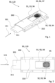
- Fig. 1 shows a ratchet system 90 in a perspective view in accordance to the invention.
- the ratchet system 90 comprises a first part 300 of the ratchet system 90 and a second part 301 of the ratchet system 90.
- the first part 300 of the ratchet system 90 is equipped with a first serration 91 with serration elements 93 in the shape of teeth 94.
- the second part 301 of the ratchet system 90 is equipped with a second serration 92 with serration elements 93 that are complementary in form and size to the teeth 94 of the first part 300 of the ratchet system 90.
- the teeth 94 of both serrations 91,92 are arranged in two rows, respectively, which are in a state of positive locking 120 with each other. Thereby, the teeth 94 of both serrations 91,92 are positioned in respective recesses formed between the teeth 94 of the respective other serration 91,92, enabling the positive locking 120 and further enabling a transmission of load between the first and second part 300,301 of the ratchet system 90.
- the shown embodiment comprises a button 95 as part of the second part 301 of the ratchet system 90, wherein the button 95 is arranged between the two rows of teeth 94 of the second serration 92.
- the row of teeth 94 are facing into opposite directions, pointing sideways away from the button 95.
- the button 95 is designed to be manually pushed against an elastic force of the second part 301 of the ratchet system 90.
- the second serration 92 can be disengaged from the positive locking 120 in a convenient way by pressing the button 95.
- the button 95 comprises a button cavity 96 and a structured surface 97 in order to facilitate the pressing and moving of the button 95 with a person's finger along a slide-in direction 111.
- the ratchet system 90 in fig. 1 further shows a first connection element 310 and a second connection element 311.
- the first connection element 310 comprises several bores, that can be used to connect the first part 300 of the ratchet system 90 to an orthotic accessory, designed to establish a connection to a person's limb, like for instance a cuff.
- the second connection element 311 can be used to connect the second part 301 of the ratchet system 90 to a module, like for example a device for establishing a form-fitting or force-fitting connection to an object. This enables a connection that can be repeatably dissolved between the orthotic accessory and the module, utilizing the ratchet system 90 as an interface.
- a module can be a device 100 as shown in fig. 8 to 10 .
- An orthotic accessory can be cuff 1 as shown in fig. 11 to 14 .
- Fig. 2 shows a top view of the ratchet system 90 in the same embodiment as in fig. 1 .
- the first connection element 310 of the interface comprises two lateral protrusions with four bores, respectively.
- the number of teeth 94 of the first part 300 of the ratchet system 90 exceeds the number of teeth 94 of the second part 301 of the ratchet system 90.
- various locking positions are enabled along a slide-in direction 111, wherein the locking position that is most to the right is selected here, such that the longitudinal extension of the ratchet system 90 is minimized.
- the slide-in direction 111 is illustrated in fig.3 .
- Fig. 3 depicts a cross sectional view of the ratchet system 90 in the same embodiment as in fig 1 . It reveals that the first serration 91 of the first part 300 of the ratchet system 90 is provided by a retainer 82, and the second serration 92 is provided by an insertion element 110, whereby the insertion element 110 can be inserted into the retainer 82 through an insertion opening 83 along the slide-in direction 111.
- the insertion element 110 is completely inserted into the retainer 82 and the serrations elements 93 in the shape of teeth 94 are in a state of positive locking 120 in a plane of engagement.
- the button 95 is located on top of a bridging section 320 of the insertion element 110 and conceals the view on the second serration 92.
- the retainer 82 encloses the insertion element 110, such that at least one rotational degree of freedom of the inserted insertion element 110 around an axis perpendicular to the slide-in direction 111 and parallel to the plane of the engagement of the serration elements 93 is blocked.
- the insertion element 110 has a portal-shaped form and has a first support element 321 located ahead the bridging section 320 and a second support element 322 located behind the bridging section 320 in relation to the slide-in direction 111.
- the support elements 321,322 support the insertion element 110 on two support parts 323,324, wherein the support parts 323,324 are integral parts of one single surface of the retainer 82. Both support elements 321,322 are protruding from the bridging section 320.
- the bridging section 320 and the second support element 322, located at the end section of the insertion element 110 undergo elastic deformation.
- the first and second serration 91,92 disengage and the insertion element 110 can be moved along a slide-in direction 111 as long as the button 95 remains pressed.
- Fig. 4 to 7 show different states of the ratchet system 90, illustrating a method of changing locking positions.
- the first serration 91 is part of a cuff 1 and the second serration 92 is part of a device according to the invention.
- the user has to press the button 95, shown in fig. 4 to 7 , and slide the insertion element 110 of the device 100 into the lower shell 11, while keeping the button 95 pressed.
- the button 95 is a special design on the insertion element 110 of the device 100, which slides into the lower shell 11. The user can then release the button 95 when the desired position is reached.
- the orthotic system comprising the cuff 1 and device 100 comprises the ratchet system 90.
- the ratchet system 90 comprises the first serration 91 provided by the lower shell 11 of the cuff 1, as well as the second serration 92 provided by the insertion element 110 of the device 100 and/ or at the button 95.
- Both components 91, 92 of the ratchet system 90 feature serration elements 93, having a shape like teeth 94. In one embodiment, these teeth 94 may have a rounded shape.
- the serration elements 93 of the first serration 91 and the second serration 92 are complementary to each other in form and size.
- the device 100 can slide along the slide-in direction 111 parallel to an arm axis. Depending on the activity and intensity, different positions of the device 100 along the y-axis might be required. This allows for the same design to be used by users with different arm lengths.
- the distance between the area of interest of the device 100 and the insertion opening 83 of the lower shell 11 as seen in fig. 14 can be adjusted by means of the ratchet system 90.
- the number of positions of the device 100 is determined by the number of serration elements 93 on the first serration 91 and the second serration 92 of the ratchet system 90.
- Fig. 4 to 7 show a method for changing the position of the device 100 with respect to the cuff.
- the button 95 is provided.
- the first serration 91 of the ratchet system 90 is provided, comprising a plurality of serration elements 93 in the shape of teeth 94, respectively.
- the second serration 92 is provided, comprising also a plurality of serration elements 93 in the shape of a teeth 94, respectively.
- the serration elements 93 of the first serration 91 and of the second serration 92 are arranged in rows, respectively, and are complementary to each other in form and size.
- Fig.4 shows a state in which the serration elements 93 of the first serration 91 and the second serration 92 engage with each other.
- a positive locking 120 is established between the lower shell 11 and the insertion element 110.
- This engaged state is maintained by means of a force 122 acting on the insertion element 110 due to elasticity of the insertion element 110.
- the button 95 When the button 95 is pressed by a pressing force 121, for instance manually, the button 95 and therefore the insertion element 110 is pressed inward against the elastic force 122, wherein the serration elements 93 of the first serration 91 and of the second serration 92 are moved out of their engagement, so that the positive locking 120 does not exist anymore, as shown in fig. 5 .
- the insertion element 110 When the insertion element 110 has been moved inward, by applying a moving force 123 on the button 95, the insertion element 110 can be moved parallel to the extension of the rows of serration elements 93 of the first serration 91 and of the second serration 92. Thus, the position of the insertion element 110 and therefore the position of the device 100 with respect to the cuff 1 can be adjusted, see fig. 6 .
- the button 95 can be released and due to elastic force 122 the insertion element 110 as well as the button 95 moves so that the serration elements 93 of the first serration 91 and of the second serration 92 engage again, shown in fig. 7 .
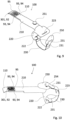
- Fig. 8 shows a device 100 in a perspective view in accordance to the invention, comprising the second part 301 of the ratchet system 90.
- the device 100 comprises a limb connection system 210 which has an elongated shape.
- Part of the limb connection system 210 is an insertion element 110 that is equipped with the second serration 92 of a ratchet system 90 comprising serration elements 93 in the shape of teeth 94 and a button 95.
- teeth 94 there are two rows of teeth 94 that are located on top of the insertion element 110.
- the row of teeth 94 are facing into opposite directions, pointing sideways away from the insertion element 110 and away from the button 95.
- the second serration 92 of the ratchet system 90 can be disengaged from a positive locking 120 in a convenient way by pressing the button 95.
- the device 100 further shows a mechanical holding mount 220, which has a cavity 221 to establish a form fitting connect with an object.
- a belt 230 with an integrated hook-and-loop fastener 231 is connected at two sides of the cavity 22.
- the form of the belt 230 illustrates how an object can be wrapped in order to fix its position. Thereby the belt 230 eventually applies tensional force to establish a force-fitting connection to the object.
- another embodiment of the device 100 comprises an identical limb connection system 210, but a different mechanical holding mount 220. Moreover, a different connection system of the belt 230 is demonstrated. Both end sections of the belt 230 comprise a hook-and-loop fastener 231, respectively. The belt 230 is shown is opened state.
- One end section of the belt 230 is threaded through a first slit 222 at the mechanical holding mount 220 and attached to itself, while the other end section is attached in a similar way to a first mounting element 250.
- the second mounting element 251 is located at the limb connection system 210. In order to close the belt 230, the first and the second mounting elements 250, 251 can be brought into a form-fitting connection.
- the mechanical holding mount comprises a second slit 223, where the belt 230 optionally can be connected or which can be used as guidance for the belt 230.
- Fig. 10 shows the device 100 in the same embodiment as shown in fig. 2 , wherein the belt 230 is in a closed state.
- the first and the second mounting elements 250, 251 are depicted in a connected state. Thereby, the first mounting element 250 blocks the view onto the second mounting element 251.
- the first mounting element 250 further comprises a bar 254, where the belt 230 is looped around and connected to itself by means of the hook-and-loop fastener 231.
- the opposite end section of the belt 230 is also equipped with a hook-and-loop fastener 231, which is connected to the first slit 222 of the mechanical holding mount 220 in a similar manner.
- the slit 223 either can be used for guidance purposes of the belt 230 or can be used to fixture one end section of the belt 230.
- the first part 300 of the ratchet system 90 can be part of a cuff 1 that is attachable to a limb in accordance to the invention.
- Fig. 11 to 14 show such a cuff 1.
- Insertion of a limb, for instance a forearm, into the cuff 1 can be difficult as, in most cases, there is an enlargement at the beginning of the palm. This makes it difficult to insert the arm into the cuff 1 from the proximal side.
- the design is divided into a cuff base 10 in form of a lower shell 11 and a fixation element 20, which can be a cuff top 30 in form of an upper shell 31.
- the shells 11, 31 can be separated as two distinct elements.
- the lower shell 11 can in this case be set radially to the axis of the arm.
- the upper shell 31 can then be coupled to the lower shell 11 to create a closed system around the forearm.
- the number of shells 11, 31 can be larger than two and rise to three, four or more, but that can be the case only if they can be linked in such a way that the user does not need to hold them all in position before tightening them together around their forearm.
- the way in which the shells can be connected to each other should be easy and effortless.
- the upper shell 31 as the fixation element 20 is connected to the lower shell 11 by means of the lacing system 60.
- the lacing element 61 in form of a cable, which is connected with a lacing knob 62. By turning of the lacing knob 62, tension is generated in the lacing element, which causes the tightening of the lacing system 60.
- the lacing system 60 may comprise a common part 54 which provides a plurality of form fit means. These can be used to interlock with additional form fit means provided at the lower shell 11 establishing a form fit connection. In fig 11 , 13 and 14 the form fit means are not illustrated, but the common part 54 is shown, respectively.
- the cuff 1 provides a cuff base 10 in form of a lower shell 11 and a fixation means 20 in form of a strap system 70.
- the strap system 70 comprises two straps 71 which are led through cutouts 73 of the cuff base 10.
- the straps 71 are provided with a hook-and-loop system 72, respectively.
- the strap system 70 can be tightened around the forearm.
- the embodiment of the cuff 1 comprising a strap system 70 is not restricted to the embodiment shown in fig. 12 .
- cushioning material 80 is applied in the cuff base 10.
- Another aspect of the design is its modularity.
- the system allows for the connection of different modules to best meet the needs of the users. Especially, it can be connected to the device 100.
- the device 100 can be inserted into the lower shell 11 of the cuff 1.
- Fig. 14 depicts the insertion of the device 100 into the cuff 1, wherein the device 100 is only partly illustrated.
- the insertion element 110 of the device 100 can be directly inserted along a slide-in direction 111 into a retainer 82, which is provided in the cuff base 10 through an insertion opening 83 which in turn is arranged at the distal end of the cuff 1, shown in fig. 13 .
- Positive locking 120 of the ratchet system 90 allows the transfer of loads along the slide-in direction 111
- the device 100 can be removed from the cuff 1, when necessary, for example, if the targeted activity changes, requiring another module.
- the orthotic system allows for outdoor activities and can be used for muscle-strengthening sessions or fitness training It can also be used in the water, for example, when kayaking. These activities require a critical degree of freedom so as not to restrict the movement of the upper limbs.
Landscapes
- Health & Medical Sciences (AREA)
- Life Sciences & Earth Sciences (AREA)
- General Health & Medical Sciences (AREA)
- Transplantation (AREA)
- Engineering & Computer Science (AREA)
- Biomedical Technology (AREA)
- Heart & Thoracic Surgery (AREA)
- Orthopedic Medicine & Surgery (AREA)
- Vascular Medicine (AREA)
- Animal Behavior & Ethology (AREA)
- Veterinary Medicine (AREA)
- Public Health (AREA)
- Cardiology (AREA)
- Oral & Maxillofacial Surgery (AREA)
- Nursing (AREA)
- Orthopedics, Nursing, And Contraception (AREA)
- Prostheses (AREA)
Applications Claiming Priority (1)
| Application Number | Priority Date | Filing Date | Title |
|---|---|---|---|
| EP23160455 | 2023-03-07 |
Publications (1)
| Publication Number | Publication Date |
|---|---|
| EP4427710A1 true EP4427710A1 (fr) | 2024-09-11 |
Family
ID=85511095
Family Applications (3)
| Application Number | Title | Priority Date | Filing Date |
|---|---|---|---|
| EP24162105.1A Pending EP4427710A1 (fr) | 2023-03-07 | 2024-03-07 | Systeme a cliquet et systeme orthetique |
| EP24162058.2A Active EP4427709B1 (fr) | 2023-03-07 | 2024-03-07 | Brassard et système orthétique |
| EP24162063.2A Pending EP4427713A1 (fr) | 2023-03-07 | 2024-03-07 | Dispositif pour établir une liaison par complémentarité de forme et/ou par liaison de force avec un objet et système orthétique |
Family Applications After (2)
| Application Number | Title | Priority Date | Filing Date |
|---|---|---|---|
| EP24162058.2A Active EP4427709B1 (fr) | 2023-03-07 | 2024-03-07 | Brassard et système orthétique |
| EP24162063.2A Pending EP4427713A1 (fr) | 2023-03-07 | 2024-03-07 | Dispositif pour établir une liaison par complémentarité de forme et/ou par liaison de force avec un objet et système orthétique |
Country Status (1)
| Country | Link |
|---|---|
| EP (3) | EP4427710A1 (fr) |
Citations (3)
| Publication number | Priority date | Publication date | Assignee | Title |
|---|---|---|---|---|
| US20090099562A1 (en) * | 2004-12-22 | 2009-04-16 | Arni Thor Ingimudarson | Orthotic device and method for securing the same |
| US9757266B2 (en) * | 2010-06-01 | 2017-09-12 | Saebo, Inc. | Orthotic device |
| US10952887B2 (en) * | 2017-02-13 | 2021-03-23 | Ossur Iceland Ehf | Orthopedic device, method, and system for making an orthopedic device |
Family Cites Families (5)
| Publication number | Priority date | Publication date | Assignee | Title |
|---|---|---|---|---|
| US3942194A (en) * | 1974-08-30 | 1976-03-09 | Sybil Betty Anna Winter | Prosthetic device for handicapped persons |
| US6575926B2 (en) * | 2000-12-15 | 2003-06-10 | Bonutti 2003 Trust-A | Myofascial strap |
| KR101895140B1 (ko) * | 2013-11-18 | 2018-09-04 | 보아 테크놀러지, 인크. | 보철 및 장구의 자동 폐쇄를 제공하기 위한 방법 및 장치 |
| DE102016108046B4 (de) * | 2016-04-29 | 2017-11-30 | Otto Bock Healthcare Products Gmbh | Prothesenschaftsystem sowie Prothesenschaft und Liner |
| US9956093B1 (en) * | 2017-03-31 | 2018-05-01 | Warren Harris | Prosthetic limb cover |
-
2024
- 2024-03-07 EP EP24162105.1A patent/EP4427710A1/fr active Pending
- 2024-03-07 EP EP24162058.2A patent/EP4427709B1/fr active Active
- 2024-03-07 EP EP24162063.2A patent/EP4427713A1/fr active Pending
Patent Citations (3)
| Publication number | Priority date | Publication date | Assignee | Title |
|---|---|---|---|---|
| US20090099562A1 (en) * | 2004-12-22 | 2009-04-16 | Arni Thor Ingimudarson | Orthotic device and method for securing the same |
| US9757266B2 (en) * | 2010-06-01 | 2017-09-12 | Saebo, Inc. | Orthotic device |
| US10952887B2 (en) * | 2017-02-13 | 2021-03-23 | Ossur Iceland Ehf | Orthopedic device, method, and system for making an orthopedic device |
Also Published As
| Publication number | Publication date |
|---|---|
| EP4427713A1 (fr) | 2024-09-11 |
| EP4427709B1 (fr) | 2025-06-04 |
| EP4427709A1 (fr) | 2024-09-11 |
| EP4427709C0 (fr) | 2025-06-04 |
Similar Documents
| Publication | Publication Date | Title |
|---|---|---|
| US12109162B2 (en) | Rope-driven soft hand function rehabilitation device | |
| JP2006528911A5 (fr) | ||
| CN105246435B (zh) | 搭扣 | |
| US20230338222A1 (en) | Self-balancing harness for wearable assistance devices | |
| EP4042982B1 (fr) | Dispositif de prothèse de pouce | |
| CN107645936A (zh) | 外部固定 | |
| US11191659B2 (en) | Joint brace with improved range of motion stop | |
| US20260060820A1 (en) | Ratchet system and orthotic system | |
| US20230100371A1 (en) | Exosuit having adjustable modular straps and bands | |
| EP4427709B1 (fr) | Brassard et système orthétique | |
| US11674336B2 (en) | Safe restraint apparatus and system | |
| US20260060829A1 (en) | Device for establishing a form-fitting and/or force-fitting connection to an object, and orthotic system | |
| US20260060818A1 (en) | Cuff and orthotic system | |
| CN106809167B (zh) | 联动解锁机构、安全防护装置及安全服衣襟 | |
| KR102085527B1 (ko) | 보행 외골격의 길이 조절 구조 및 이를 포함하는 보행 외골격 | |
| US20030121525A1 (en) | Rapid deployment soft restraint apparatus and method | |
| US11819435B2 (en) | Device for providing active assistance to a body joint | |
| JP7046116B2 (ja) | 装具の継手装置 | |
| US20240307249A1 (en) | Device and method for arrangement on a body comprising an essentially rotation-symmetric portion, and method for moving and/or manipulation of an object using the device | |
| KR20260010384A (ko) | 손가락 신장을 위한 부드러운 슬라이딩 메커니즘 | |
| US20020092530A1 (en) | Rapid deployment soft restraint apparatus and method | |
| US20030066535A1 (en) | Multi-point soft restraint apparatus and method | |
| KR102956535B1 (ko) | 웨어러블 슈트 | |
| KR100267016B1 (ko) | 상지의지의 손목관절 | |
| JP7199721B2 (ja) | リハビリ機能付き創外固定器 |
Legal Events
| Date | Code | Title | Description |
|---|---|---|---|
| PUAI | Public reference made under article 153(3) epc to a published international application that has entered the european phase |
Free format text: ORIGINAL CODE: 0009012 |
|
| STAA | Information on the status of an ep patent application or granted ep patent |
Free format text: STATUS: THE APPLICATION HAS BEEN PUBLISHED |
|
| AK | Designated contracting states |
Kind code of ref document: A1 Designated state(s): AL AT BE BG CH CY CZ DE DK EE ES FI FR GB GR HR HU IE IS IT LI LT LU LV MC ME MK MT NL NO PL PT RO RS SE SI SK SM TR |
|
| STAA | Information on the status of an ep patent application or granted ep patent |
Free format text: STATUS: REQUEST FOR EXAMINATION WAS MADE |
|
| 17P | Request for examination filed |
Effective date: 20241127 |
|
| RBV | Designated contracting states (corrected) |
Designated state(s): AL AT BE BG CH CY CZ DE DK EE ES FI FR GB GR HR HU IE IS IT LI LT LU LV MC ME MK MT NL NO PL PT RO RS SE SI SK SM TR |
|
| STAA | Information on the status of an ep patent application or granted ep patent |
Free format text: STATUS: EXAMINATION IS IN PROGRESS |
|
| 17Q | First examination report despatched |
Effective date: 20250213 |