EP4427794A1 - Mikronadelanordnung - Google Patents
Mikronadelanordnung Download PDFInfo
- Publication number
- EP4427794A1 EP4427794A1 EP22904473.0A EP22904473A EP4427794A1 EP 4427794 A1 EP4427794 A1 EP 4427794A1 EP 22904473 A EP22904473 A EP 22904473A EP 4427794 A1 EP4427794 A1 EP 4427794A1
- Authority
- EP
- European Patent Office
- Prior art keywords
- microneedles
- applicator
- mold
- microneedle assembly
- microneedle
- Prior art date
- Legal status (The legal status is an assumption and is not a legal conclusion. Google has not performed a legal analysis and makes no representation as to the accuracy of the status listed.)
- Pending
Links
Images


Classifications
-
- A—HUMAN NECESSITIES
- A61—MEDICAL OR VETERINARY SCIENCE; HYGIENE
- A61M—DEVICES FOR INTRODUCING MEDIA INTO, OR ONTO, THE BODY; DEVICES FOR TRANSDUCING BODY MEDIA OR FOR TAKING MEDIA FROM THE BODY; DEVICES FOR PRODUCING OR ENDING SLEEP OR STUPOR
- A61M37/00—Other apparatus for introducing media into the body; Percutany, i.e. introducing medicines into the body by diffusion through the skin
- A61M37/0015—Other apparatus for introducing media into the body; Percutany, i.e. introducing medicines into the body by diffusion through the skin by using microneedles
-
- A—HUMAN NECESSITIES
- A61—MEDICAL OR VETERINARY SCIENCE; HYGIENE
- A61M—DEVICES FOR INTRODUCING MEDIA INTO, OR ONTO, THE BODY; DEVICES FOR TRANSDUCING BODY MEDIA OR FOR TAKING MEDIA FROM THE BODY; DEVICES FOR PRODUCING OR ENDING SLEEP OR STUPOR
- A61M37/00—Other apparatus for introducing media into the body; Percutany, i.e. introducing medicines into the body by diffusion through the skin
- A61M37/0015—Other apparatus for introducing media into the body; Percutany, i.e. introducing medicines into the body by diffusion through the skin by using microneedles
- A61M2037/0023—Drug applicators using microneedles
-
- A—HUMAN NECESSITIES
- A61—MEDICAL OR VETERINARY SCIENCE; HYGIENE
- A61M—DEVICES FOR INTRODUCING MEDIA INTO, OR ONTO, THE BODY; DEVICES FOR TRANSDUCING BODY MEDIA OR FOR TAKING MEDIA FROM THE BODY; DEVICES FOR PRODUCING OR ENDING SLEEP OR STUPOR
- A61M37/00—Other apparatus for introducing media into the body; Percutany, i.e. introducing medicines into the body by diffusion through the skin
- A61M37/0015—Other apparatus for introducing media into the body; Percutany, i.e. introducing medicines into the body by diffusion through the skin by using microneedles
- A61M2037/0046—Solid microneedles
-
- A—HUMAN NECESSITIES
- A61—MEDICAL OR VETERINARY SCIENCE; HYGIENE
- A61M—DEVICES FOR INTRODUCING MEDIA INTO, OR ONTO, THE BODY; DEVICES FOR TRANSDUCING BODY MEDIA OR FOR TAKING MEDIA FROM THE BODY; DEVICES FOR PRODUCING OR ENDING SLEEP OR STUPOR
- A61M37/00—Other apparatus for introducing media into the body; Percutany, i.e. introducing medicines into the body by diffusion through the skin
- A61M37/0015—Other apparatus for introducing media into the body; Percutany, i.e. introducing medicines into the body by diffusion through the skin by using microneedles
- A61M2037/0053—Methods for producing microneedles
-
- A—HUMAN NECESSITIES
- A61—MEDICAL OR VETERINARY SCIENCE; HYGIENE
- A61M—DEVICES FOR INTRODUCING MEDIA INTO, OR ONTO, THE BODY; DEVICES FOR TRANSDUCING BODY MEDIA OR FOR TAKING MEDIA FROM THE BODY; DEVICES FOR PRODUCING OR ENDING SLEEP OR STUPOR
- A61M37/00—Other apparatus for introducing media into the body; Percutany, i.e. introducing medicines into the body by diffusion through the skin
- A61M37/0015—Other apparatus for introducing media into the body; Percutany, i.e. introducing medicines into the body by diffusion through the skin by using microneedles
- A61M2037/0061—Methods for using microneedles
Definitions
- the present disclosure relates to a microneedle assembly, and more specifically, to a microneedle assembly which is capable of safely keeping microneedles and applying the microneedles to a skin in a convenient manner while preventing the microneedles from being contaminated during use.
- dissolvable microneedles Delivery of pharmaceutical agents to a skin using dissolvable microneedles is greatly affected by mechanochemical properties such as a shape, physical property and solubility of the dissolvable microneedles, as well as application conditions such as a dosage (insertion) state and a dosage time. Accordingly, under inappropriate application conditions, the dissolvable microneedles may not be sufficiently inserted into a dermal layer of the skin, and therefore, a fixed quantity of pharmaceutical agents may not be delivered to the skin.
- the microneedles may not be sufficiently inserted into the dermal layer of the skin.
- the pressure is applied unevenly over the entire area of an array of the microneedles, or when a force is applied in a shear direction, the microneedles may be inserted unevenly into the skin.
- an aspect ratio of each microneedle may be decreased due to dissolution of a polymer, and the array of the microneedles may be displaced due to an elasticity of the skin itself and an external movement.
- the microneedles when the user inserts the microneedles into the skin by taking out a microneedle patch from a storage container, attaching the same to the skin, and pressing the microneedle patch while rubbing the microneedle patch, the microneedles may not be inserted perpendicularly into the skin or may be bent. Further, the microneedles may be contaminated by user's fingers.
- the present disclosure was made for the purpose of solving the above matters, and the present disclosure is for the purpose of a microneedle assembly which is capable of safely keeping microneedles and applying the microneedles to a skin in a convenient manner while preventing the microneedles from being contaminated during use.
- An example embodiment of the present disclosure provides a microneedle assembly which may include: a mold having one or more concave portions formed in an upper surface thereof and microneedles molded by being injected into the one or more concave portions; and
- the applicator may further include one or more pressing protrusions provided at positions corresponding to the microneedles on the second surface, and having one end portions formed to be flat, and the adhesion portions may be formed on the one end portions of the one or more pressing protrusions.
- the mold may further include one or more guide protrusions formed outside an area where the microneedles are formed.
- the applicator may be formed outside an area where the one or more pressing protrusions are formed, and may further include one or more guide holes into which the one or more guide protrusions are inserted.
- the mold and the applicator may be coupled to each other by the one or more guide protrusions and the one or more guide holes during packaging.
- the one or more guide protrusions and the one or more guide holes may be configured to guide the adhesion portion toward the microneedles during use.
- the microneedle assembly may further include a protection cover configured to be detachably coupled to the second surface of the applicator during packaging and temporarily close the second surface.
- the applicator may be made of a sturdy material.
- the one or more concave portions of the mold may be sharp-tipped concave portions.
- microneedles may be provided independently of each other.
- the mold may be a primary packaging container in a full close contact with the microneedles and may be configured to be removed before the microneedles are applied to a human body.
- the one or more guide holes may be formed to penetrate from the first surface to the second surface of the applicator.
- microneedles may be kept in a safe manner so as not to be exposed to the outside, and may be applied to a skin in a convenient manner using an applicator during use.
- the applicator includes one or more pressing protrusions and one or more adhesion portions provided at positions corresponding to the microneedles formed in a mold. This makes it possible to more easily separate the microneedles from the mold and penetrate the microneedles to the skin with uniform pressure.
- one constituent element when one constituent element is referred to as being “connected” to another constituent element, the one constituent element may be “directly connected” to another constituent element, or may be “indirectly connected” to another constituent element by intervening yet another constituent element therebetween. Further, when one constituent element "comprise or includes” another constituent element through the specification, this means that the one constituent element may further include other constituent elements, rather than excluding other constituent elements, unless other stated.
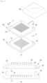
- FIG. 1A is a perspective view of a microneedle assembly according to an example embodiment of the present disclosure
- FIG. 1B is a cross-sectional view taken along line A-A' in FIG. 1A
- FIG. 2A is an exploded perspective view of the microneedle assembly according to the example embodiment of the present disclosure
- FIG. 2B is a cross-sectional view taken along line B-B' in FIG. 2A
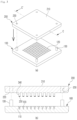
- FIG. 3A is a perspective view of a mold and an applicator before microneedles are separated from the mold in an example embodiment of the present disclosure
- FIG. 3B is a cross-sectional view taken along line C-C' in FIG. 3A .
- FIG. 4A is a perspective view of the mold and the applicator when the microneedles are attached to the mold in an example embodiment of the present disclosure
- FIG. 4B is a cross-sectional view taken along line D-D' in FIG. 4A
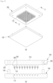
- FIG. 5A is a perspective view of the mold and the applicator after the microneedles are separated from the mold in an example embodiment of the present disclosure
- FIG. 5B is a cross-sectional view taken along line E-E' in FIG. 5A
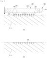
- FIGS. 6A and 6B are state diagrams illustrating states before and after the microneedles is applied to the human body using the applicator according to an example embodiment of the present disclosure, respectively.
- a microneedle assembly 1000 of the present disclosure includes a mold 100, an applicator 200, and a protection cover 300.
- the microneedle assembly 1000 is provided with the mold 100 including one or more concave portions 110 formed in an upper surface thereof and microneedles 120 injected into the concave portions 110 to be molded therein, and the applicator 200 detachably coupled to the upper surface of the mold 100.
- the applicator 200 is formed in a plate shape.
- the applicator 200 has a first surface 210 for protecting the microneedles 120 from being exposed during packaging, and a second surface 220 to be attached to the microneedles 120 when the applicator 200 is used.
- the adhesion portion 250 is formed on the second surface 220 to separate the microneedles 120 from the mold 100.
- the mold 100 may have one or more concave portions 110 formed in the upper surface thereof.
- a lower surface of the mold 100 may be flat.
- Each of the concave portions 110 acts as a mold for each microneedle 120 and may have a shape corresponding to the microneedle 120.
- each concave portion 110 may be a fine-tipped concave portion.
- fine-tipped concave portion means a concave portion depressed downward from a flat upper surface such that a cross-sectional area thereof is reduced from the flat upper surface toward a lower surface forming a tip, like a shape of the typical microneedle 120.
- upper surface and/or “lower surface” used herein is for specifying a relative positional relationship in each configuration and does not specify absolute positions thereof.
- the concave portions 110 may be provided in the form of an array independently of each other on the upper surface of the mold 100 without being connected to each other in the upper surface of the mold 100.
- the microneedles 120 molded by being injected into the concave portions 110 may also be provided in the form of an array independently of each other without being connected to each other.
- the microneedles 120 may be separated from the respective concave portions 110 of the mold 100 by the adhesion portion 250 of the applicator 200.
- the microneedles 120 may be formed by molding a raw material containing one or more selected from the group consisting of a non-metal, a biodegradable polymer, and pharmaceutical ingredients with the concave portions 110 of the mold 100.
- the mold 100 may be made of a solid material.
- the mold 100 may be made of any suitable material, preferably a plastic resin.
- the mold 100 may be made of at least one or more selected from the group consisting of polyethyleneterephthalate (PET), polyvinylchloride (PVC), and polypropylene (PP), but is not limited thereto.
- PET polyethyleneterephthalate
- PVC polyvinylchloride
- PP polypropylene
- a microneedle made of a silicon material in the related art is expensive, thus the silicon microneedle in the related art often needs to be reused.
- verification of a cleaning validation (CV) of fine concave portions in which microneedles are molded may be a difficult process to conduct.
- Verification of a permeability of a cleaning solvent to silicon may also be a difficult process.
- the silicon material is physicochemically decomposable and has a relatively weak hardness. As a result, fragments may be generated during a manufacturing or cleaning process. In addition, it is difficult to determine a lifespan of a mold made of the silicon material.
- the silicon does not play a protective role for ambient air or external foreign matters.
- dried microneedles need to be removed from the mold to repackage the same.
- the microneedles since it is practically difficult to individually pack each of the fine-sized microneedles in an airtight manner, the microneedles may be packaged in a pouch or a container while being exposed to ambient air.
- the sealability and stability of a packaging container have a significant effect on maintaining the quality of pharmaceuticals in the packaging container. Therefore, the packaging container needs to completely prevent physicochemical deformation or deterioration of the pharmaceuticals in the packaging container through a transport condition simulation and mechanical test relating to final products.
- the mold 100 of the present disclosure may function as a primary packaging container in a full close contact with the microneedles 120 without removing and repackaging the microneedles 120 molded in the concave portions 110.
- the mold 100 may be configured to be removed before use. This makes it possible to simplify an operation of packaging the microneedles and easily maintain the quality of the microneedles.
- the applicator 200 is configured to separate the microneedles 120 from the mold 100 and allow the separated microneedles 120 to penetrate into the skin of the human body.
- the applicator 200 may be formed in a plate shape and may have the first surface 210 and the second surface 220.
- the first surface 210 covers the upper surface of the mold 100 during packaging to protect the microneedles 120 from being exposed to the outside.
- the second surface 220 has one or more adhesion portions 250 formed at positions corresponding to the microneedles 120.
- the adhesion portions 250 adhere to the microneedles 120 so as to separate the microneedles 120 from the mold 100.
- the applicator 200 may be made of a solid material.
- the applicator 200 may be made of any suitable material, preferably a plastic resin.
- the applicator 200 may be made of at least one or more selected from the group consisting of polyethyleneterephthalate (PET), polyvinylchloride (PVC), and polypropylene (PP), but is not limited thereto.
- PET polyethyleneterephthalate
- PVC polyvinylchloride
- PP polypropylene
- the applicator 200 may further have one or more pressing protrusions 240 provided at positions corresponding to the respective microneedles 120 on the second surface 220.
- One end portion of each pressing protrusion 240 is flat.
- the pressing protrusion 240 may be formed in a cylindrical shape, but is not limited thereto.
- the pressing protrusion 240 may be formed in a polygonal pillar shape such as a triangular pillar or square pillar.
- the pressing protrusions 240 are formed to be the same as the number of the microneedles 120 at the positions corresponding to the microneedles 120 on the second surface 220.
- Each adhesion portion 250 may be formed on one end portion of the pressing protrusion 240.
- the applicator 200 is configured such that the pressing protrusions 240 are provided at the positions corresponding to the microneedles 120. This makes it possible to easily separate the microneedles 120 from the mold 100 and let the array of the microneedles 120 penetrate into the skin with uniform pressure throughout.
- the applicator 200 may set a depth at which the microneedle 120 is inserted into the skin with a height of the pressing protrusion 240.
- the applicator 200 may be detachably coupled to the upper surface of the mold 100.
- the mold 100 may further include one or more guide protrusions 130 formed outside an area where the microneedles 120 are formed on the upper surface of the mold 100.
- the applicator 200 may further include one or more guide holes 230 formed outside an area where the pressing protrusions 240 are formed. The guide protrusions 130 are inserted into the respective guide holes 230. In this configuration, by the guide protrusions 130 and the guide holes 230, the mold 100 and the applicator 200 are coupled to each other during packaging. When the applicator 200 is used, the adhesion portion 250 may be guided toward the respective microneedles 120.
- the guide protrusions 130 are inserted into the respective guide holes 230 so that the mold 100 and the applicator 200 are coupled to each other.
- the guide protrusions 130 are guided into the respective guide holes 230 so that the adhesion portion 250 formed on the pressing protrusions 240 of the applicator 200 easily adhere to the respective microneedles 120.
- the guide protrusion 130 may be formed in a circular pillar shape, but is not limited thereto.
- the guide protrusion 130 may be formed in a polygonal pillar shape such as a triangular pillar or square pillar.
- the guide hole 230 may be formed in a shape corresponding to the guide protrusion 130.
- the guide hole 230 may be formed to penetrate from the first surface 210 to the second surface 220 of the applicator 200. With this configuration, the guide protrusion 130 may be inserted into the guide hole 230 on both the first surface 210 and the second surface 220 of the applicator 200, that is, in both directions of the applicator 200.
- a binding force between a lateral side of the microneedle 120 and the concave portion 110 is greater than an adhesive force between the adhesion portion 250 and an upper surface of the microneedle 120, when the microneedle 120 is separated from the concave portion 110 for application to the skin, the microneedle 120 may not be fully separated from the concave portion 110. This makes it difficult to dose a required amount of active pharmaceutical ingredients contained in the microneedle 120 into the skin.
- a composition of the adhesion portion 250 and the resulting adhesive force may be adjusted, and/or the concave portion 110 in contact with the microneedle 120 may be coated with a certain material and/or a surface thereof may be treated to have a certain level of roughness.
- the microneedle assembly 1000 may further include a protection cover 300 detachably coupled to the second surface 220 of the applicator 200 during packaging and configured to temporarily close the second surface 220.
- the protection cover 300 may have a structure in which a lower portion is open.
- the protection cover 300 may be formed to have an internal depth more inwardly depressed than the heights of the pressing protrusions 240 so as not to come contact with the pressing protrusions 240 of the applicator 200 during packaging. Further, the protection cover 300 may be bonded or coupled to the applicator 200 along an edge of the protection cover 300.
- a method of using the microneedle assembly 1000 is as follows.
- the protection cover 300 temporarily adhered or coupled to cover the applicator 200 is removed to expose the applicator 200 provided on the mold 100 to the outside.
- the applicator 200 coupled to the mold 100 to cover the upper surface of the mold 100 is separated from the mold 100. That is, force is applied to move the applicator 200 away from the mold 100 so that the guide protrusions 130 are separated from the respective guide holes 230.
- the applicator 200 is turned over and arranged such that the pressing protrusions 240 and the adhesion portions 250 formed on the respective pressing protrusions 240 face the mold 100 in which the microneedles 120 are formed.
- the applicator 200 is moved toward the mold 100 such that the adhesion portions 250 are attached to the microneedles 120, respectively.
- the movement of the applicator 200 to the mold 100 may be guided by the guide holes 230 and the guide protrusions 130.
- the microneedles 120 attached to the adhesion portions 250 are separated from the concave portions 110 of the mold 100. Thereafter, the first surface 210 of the applicator 200 is pressed for the microneedles 120 to penetrate into the skin.
- the applicator 200 may be made of a solid material. By the pressing protrusions 240 provided in the applicator 200, the microneedles 120 may penetrate into the skin with uniform pressure over the entire area.
Landscapes
- Health & Medical Sciences (AREA)
- Engineering & Computer Science (AREA)
- Dermatology (AREA)
- Medical Informatics (AREA)
- Anesthesiology (AREA)
- Biomedical Technology (AREA)
- Heart & Thoracic Surgery (AREA)
- Hematology (AREA)
- Life Sciences & Earth Sciences (AREA)
- Animal Behavior & Ethology (AREA)
- General Health & Medical Sciences (AREA)
- Public Health (AREA)
- Veterinary Medicine (AREA)
- Media Introduction/Drainage Providing Device (AREA)
Applications Claiming Priority (2)
| Application Number | Priority Date | Filing Date | Title |
|---|---|---|---|
| KR1020210174179A KR102425556B1 (ko) | 2021-12-07 | 2021-12-07 | 마이크로니들 조립체 |
| PCT/KR2022/017102 WO2023106639A1 (ko) | 2021-12-07 | 2022-11-03 | 마이크로니들 조립체 |
Publications (2)
| Publication Number | Publication Date |
|---|---|
| EP4427794A1 true EP4427794A1 (de) | 2024-09-11 |
| EP4427794A4 EP4427794A4 (de) | 2025-03-05 |
Family
ID=82606312
Family Applications (1)
| Application Number | Title | Priority Date | Filing Date |
|---|---|---|---|
| EP22904473.0A Pending EP4427794A4 (de) | 2021-12-07 | 2022-11-03 | Mikronadelanordnung |
Country Status (7)
| Country | Link |
|---|---|
| US (1) | US20240316326A1 (de) |
| EP (1) | EP4427794A4 (de) |
| JP (2) | JP2024542281A (de) |
| KR (1) | KR102425556B1 (de) |
| CN (1) | CN118354810A (de) |
| AU (1) | AU2022405961B2 (de) |
| WO (1) | WO2023106639A1 (de) |
Families Citing this family (1)
| Publication number | Priority date | Publication date | Assignee | Title |
|---|---|---|---|---|
| KR102425556B1 (ko) * | 2021-12-07 | 2022-07-29 | 주식회사 대웅테라퓨틱스 | 마이크로니들 조립체 |
Family Cites Families (13)
| Publication number | Priority date | Publication date | Assignee | Title |
|---|---|---|---|---|
| WO2008020632A1 (en) * | 2006-08-18 | 2008-02-21 | Toppan Printing Co., Ltd. | Microneedle and microneedle patch |
| JP5584202B2 (ja) * | 2008-05-21 | 2014-09-03 | セラジェクト, インコーポレイテッド | 固溶体穿孔器パッチの製造方法及びその使用 |
| JP2010094414A (ja) * | 2008-10-20 | 2010-04-30 | Kyokko Seiko Co Ltd | マイクロニードルシート貼付剤とその製造方法および製造装置 |
| KR101033514B1 (ko) | 2009-06-02 | 2011-05-09 | (주)마이티시스템 | 유연한 미세바늘 패치 시스템 및 그 제작방법 |
| CA2925333C (en) * | 2013-09-30 | 2021-09-07 | Georgia Tech Research Corporation | Microneedle patches, systems, and methods |
| JP6347960B2 (ja) * | 2014-01-29 | 2018-06-27 | Asti株式会社 | マイクロニードルユニットと注射装置 |
| TW201600130A (zh) * | 2014-03-26 | 2016-01-01 | 日本寫真印刷股份有限公司 | 錐狀突起片的包裝體及其製造方法 |
| KR101757866B1 (ko) * | 2015-10-08 | 2017-07-14 | 주식회사 라파스 | 마이크로니들패치 포장케이스 |
| EP3444004B1 (de) * | 2016-04-15 | 2020-12-02 | FUJIFILM Corporation | Mikronadelarray |
| WO2018220926A1 (ja) * | 2017-05-30 | 2018-12-06 | Nissha株式会社 | マイクロニードルパッチとその梱包体 |
| KR102184940B1 (ko) * | 2017-11-15 | 2020-12-01 | 주식회사 엘지생활건강 | 마이크로니들 연속 제조용 장치 및 공정 |
| KR20200106824A (ko) * | 2019-03-04 | 2020-09-15 | 주식회사 대웅테라퓨틱스 | 마이크로니들 어레이 및 이의 제조방법 |
| KR102425556B1 (ko) * | 2021-12-07 | 2022-07-29 | 주식회사 대웅테라퓨틱스 | 마이크로니들 조립체 |
-
2021
- 2021-12-07 KR KR1020210174179A patent/KR102425556B1/ko active Active
-
2022
- 2022-11-03 AU AU2022405961A patent/AU2022405961B2/en active Active
- 2022-11-03 WO PCT/KR2022/017102 patent/WO2023106639A1/ko not_active Ceased
- 2022-11-03 JP JP2024532806A patent/JP2024542281A/ja active Pending
- 2022-11-03 EP EP22904473.0A patent/EP4427794A4/de active Pending
- 2022-11-03 CN CN202280080172.7A patent/CN118354810A/zh active Pending
-
2024
- 2024-06-04 US US18/733,058 patent/US20240316326A1/en active Pending
-
2025
- 2025-11-06 JP JP2025187338A patent/JP2026016768A/ja active Pending
Also Published As
| Publication number | Publication date |
|---|---|
| JP2024542281A (ja) | 2024-11-13 |
| CN118354810A (zh) | 2024-07-16 |
| US20240316326A1 (en) | 2024-09-26 |
| AU2022405961B2 (en) | 2025-01-30 |
| AU2022405961A1 (en) | 2024-05-30 |
| EP4427794A4 (de) | 2025-03-05 |
| KR102425556B1 (ko) | 2022-07-29 |
| WO2023106639A1 (ko) | 2023-06-15 |
| JP2026016768A (ja) | 2026-02-03 |
Similar Documents
| Publication | Publication Date | Title |
|---|---|---|
| CN112089961B (zh) | 微针贴片施用器及其壳体 | |
| US11123531B2 (en) | Integrated-type microneedle patch | |
| EP1904158B1 (de) | Faltbares Pflaster mit Mikronadelnanordnung | |
| EP4108287B1 (de) | Mikronadelanordnungseinheit | |
| US20240316326A1 (en) | Microneedle assembly | |
| CN108853710A (zh) | 微针阵列单元及容器 | |
| WO2008007906A1 (en) | Transdermal delivery apparatus | |
| KR20170063591A (ko) | 마이크로니들 시트의 곤포체 및 그 제조 방법 | |
| KR20240007890A (ko) | 마이크로니들 어레이 및 이의 제조방법 | |
| CN112295100A (zh) | 微针阵列的制造方法、微针阵列及微针阵列单元 | |
| WO2019216097A1 (ja) | マイクロニードルアレイユニットの製造方法 | |
| KR20230148800A (ko) | 마이크로니들 어레이 및 이의 제조방법 | |
| KR102427901B1 (ko) | 마이크로니들 제조방법 | |
| KR102592223B1 (ko) | 마이크로니들 어레이의 제조방법 | |
| US10596040B2 (en) | Transdermal administration device | |
| KR101553742B1 (ko) | 경피 투여 장치 및 그 제조 방법 | |
| JP2017529114A (ja) | 医療用パッチを製造するための装置 | |
| HK40107478A (zh) | 微针组件 | |
| KR20190107538A (ko) | 마이크로니들 어플리케이터 | |
| CN112969495A (zh) | 微针阵列单元 | |
| KR20220065655A (ko) | 마이크로니들 어레이 및 이의 제조방법 | |
| JP2017209427A (ja) | 経皮投与デバイス、および、薬剤投与器具 |
Legal Events
| Date | Code | Title | Description |
|---|---|---|---|
| STAA | Information on the status of an ep patent application or granted ep patent |
Free format text: STATUS: THE INTERNATIONAL PUBLICATION HAS BEEN MADE |
|
| PUAI | Public reference made under article 153(3) epc to a published international application that has entered the european phase |
Free format text: ORIGINAL CODE: 0009012 |
|
| STAA | Information on the status of an ep patent application or granted ep patent |
Free format text: STATUS: REQUEST FOR EXAMINATION WAS MADE |
|
| 17P | Request for examination filed |
Effective date: 20240605 |
|
| AK | Designated contracting states |
Kind code of ref document: A1 Designated state(s): AL AT BE BG CH CY CZ DE DK EE ES FI FR GB GR HR HU IE IS IT LI LT LU LV MC ME MK MT NL NO PL PT RO RS SE SI SK SM TR |
|
| A4 | Supplementary search report drawn up and despatched |
Effective date: 20250204 |
|
| RIC1 | Information provided on ipc code assigned before grant |
Ipc: A61M 37/00 20060101AFI20250129BHEP |
|
| DAV | Request for validation of the european patent (deleted) | ||
| DAX | Request for extension of the european patent (deleted) |