EP4428026A1 - Schwimmende betonstruktur für offshore-windanwendungen und verfahren zur herstellung solch einer schwimmenden struktur - Google Patents
Schwimmende betonstruktur für offshore-windanwendungen und verfahren zur herstellung solch einer schwimmenden struktur Download PDFInfo
- Publication number
- EP4428026A1 EP4428026A1 EP23382228.7A EP23382228A EP4428026A1 EP 4428026 A1 EP4428026 A1 EP 4428026A1 EP 23382228 A EP23382228 A EP 23382228A EP 4428026 A1 EP4428026 A1 EP 4428026A1
- Authority
- EP
- European Patent Office
- Prior art keywords
- pontoon
- inner column
- column
- beams
- concrete structure
- Prior art date
- Legal status (The legal status is an assumption and is not a legal conclusion. Google has not performed a legal analysis and makes no representation as to the accuracy of the status listed.)
- Pending
Links
Images

Classifications
-
- B—PERFORMING OPERATIONS; TRANSPORTING
- B63—SHIPS OR OTHER WATERBORNE VESSELS; RELATED EQUIPMENT
- B63B—SHIPS OR OTHER WATERBORNE VESSELS; EQUIPMENT FOR SHIPPING
- B63B1/00—Hydrodynamic or hydrostatic features of hulls or of hydrofoils
- B63B1/02—Hydrodynamic or hydrostatic features of hulls or of hydrofoils deriving lift mainly from water displacement
- B63B1/10—Hydrodynamic or hydrostatic features of hulls or of hydrofoils deriving lift mainly from water displacement with multiple hulls
- B63B1/107—Semi-submersibles; Small waterline area multiple hull vessels and the like, e.g. SWATH
-
- B—PERFORMING OPERATIONS; TRANSPORTING
- B63—SHIPS OR OTHER WATERBORNE VESSELS; RELATED EQUIPMENT
- B63B—SHIPS OR OTHER WATERBORNE VESSELS; EQUIPMENT FOR SHIPPING
- B63B1/00—Hydrodynamic or hydrostatic features of hulls or of hydrofoils
- B63B1/02—Hydrodynamic or hydrostatic features of hulls or of hydrofoils deriving lift mainly from water displacement
- B63B1/04—Hydrodynamic or hydrostatic features of hulls or of hydrofoils deriving lift mainly from water displacement with single hull
- B63B2001/044—Hydrodynamic or hydrostatic features of hulls or of hydrofoils deriving lift mainly from water displacement with single hull with a small waterline area compared to total displacement, e.g. of semi-submersible type
-
- B—PERFORMING OPERATIONS; TRANSPORTING
- B63—SHIPS OR OTHER WATERBORNE VESSELS; RELATED EQUIPMENT
- B63B—SHIPS OR OTHER WATERBORNE VESSELS; EQUIPMENT FOR SHIPPING
- B63B35/00—Vessels or similar floating structures specially adapted for specific purposes and not otherwise provided for
- B63B35/44—Floating buildings, stores, drilling platforms, or workshops, e.g. carrying water-oil separating devices
- B63B2035/4433—Floating structures carrying electric power plants
- B63B2035/446—Floating structures carrying electric power plants for converting wind energy into electric energy
-
- F—MECHANICAL ENGINEERING; LIGHTING; HEATING; WEAPONS; BLASTING
- F03—MACHINES OR ENGINES FOR LIQUIDS; WIND, SPRING, OR WEIGHT MOTORS; PRODUCING MECHANICAL POWER OR A REACTIVE PROPULSIVE THRUST, NOT OTHERWISE PROVIDED FOR
- F03D—WIND MOTORS
- F03D13/00—Assembly, mounting or commissioning of wind motors; Arrangements specially adapted for transporting wind motor components
- F03D13/20—Arrangements for mounting or supporting wind motors; Masts or towers for wind motors
- F03D13/25—Arrangements for mounting or supporting wind motors; Masts or towers for wind motors specially adapted for offshore installation
- F03D13/256—Arrangements for mounting or supporting wind motors; Masts or towers for wind motors specially adapted for offshore installation on a floating support, i.e. floating wind motors
Definitions
- the present invention belongs to the construction and naval technology sector. Specifically, the invention relates to marine structures in the open sea, also called offshore structures, and particularly to semi-submersible offshore floating structures, the purpose of which is to support the development of industrial and/or energy activities.
- Offshore wind technology has been identified as one of the technologies that should lead the decarbonisation of the European energy mix in the coming decades.
- the European Commission estimates that, to meet the objectives of the fight against climate change, an installed capacity of between 240 and 450 GW of offshore wind energy is required by 2050. It is expected that, by then, electricity will represent at least 50% of the total energy mix, with 30% of the demand being supplied by offshore wind energy.
- TLP Transmission Leg Platform
- Sami-taut Systems made up of elastomers, tendons, steel cables, etc.
- construction costs are included, which vary depending on the design and complexity of the structure, as well as the base material to be used, this being mainly steel.
- OPEX mainly the operating and exploitation costs derived from power generation and maintenance costs are included therein, together with the cost of means for accessing the park, among others.
- the OPEX is closely linked, not only to the investment in the maintenance of the rotating elements and equipment of the platform, but also to the work to be carried out on the structure to ensure the integrity thereof during its service life.
- the design strategy seeks, on the one hand, to minimise the LCOE by acting on the different design variables in favour of a more competitive technological solution.
- the promoters of floating offshore wind parks encourage the search for platform typologies that allow the reduction of the OPEX, as well as reducing risks in the supply chain through the industrialisation of construction processes, and the consequent reduction of financial and economic risks.
- this intermediate bracing system requires post-tensioning of all the columns, once the climbing or slip-forming process has been completed.
- This post-tensioning system in addition to making the solution more expensive, entails significant technical difficulties, derived from the height of the columns.
- a load transmission system is required, generally a metallic structure connected to the concrete structure that derives in an element having great technical complexity and therefore an increase in the cost of the solution despite its industrialisation potential through prefabricated strategies.
- the invention that is the object of this application attempts to solve all the previous drawbacks, both from the point of view of the design of the platform and the construction processes.
- the invention relates to a floating concrete structure for offshore applications, which comprises a lightweight semi-submersible platform which in turn comprises:
- the floating structure object of the invention comprises a pontoon, the inner column and the plurality of outer columns being supported, that is, resting on the pontoon.
- the plurality of beams comprises first beams which extend parallel to the pontoon between the upper portion of the inner column to a point of attachment with the outer columns. Therefore, the outer columns have the same or greater height than the inner column. Beam is understood as a linear structural element.
- the floating concrete structure is a structure made of concrete that is hollow and which comprises inner partitions that reinforce and compartmentalise the structure internally.
- a column is understood to mean a structure having a hollow and closed cross section.
- the columns can comprise, for example, a quadrangular, circular or polygonal cross section.
- Said section can be formed by walls that are intended to shape the perimeter of the column, forming a cylinder or a prism, for example.
- the cross section can be formed by the same partitions of the floating structure crossing each other and forming a hollow and closed cross section in one portion of the structure, thus defining the mentioned column.
- a pontoon is understood to be a floating structure that constitutes a resistant base having a length much greater than its thickness, flat and parallelepiped, that is, the pontoon is a flat slab.
- the pontoon comprises a lower base and an upper base and, for example, a series of inner partitions. Therefore, the first beams would run parallel to the lower base and the upper base of the pontoon.
- the pontoon is made of concrete.
- the pontoon is configured to increase the hydrodynamic damping of vertical movements, and provide the structure with buoyancy and reduce the draught of the structure in its different phases. Likewise, from the structural point of view, the pontoons provide stiffness and resistance in the direction of the length and beam, being the support for the stabilising columns.
- the present invention tries to solve the previously mentioned drawbacks by means of a lightweight semi-submersible concrete platform which may be cross-based in an embodiment and a method of construction thereof that does not require special infrastructures.
- the wind turbine tower can be located both on the inner column and on one of the outer columns, that is, eccentrically. In this case, the structure can be balanced using proper ballasting.
- the inner column has at least the tower, the nacelle, a rotor and the plurality of blades mounted.
- the semi-submersible platform comprises a central inner column and four stabilising outer columns attached together by means of a cross-shaped pontoon or resistant base. The columns are placed at each of the extremities of the cross.
- the outer columns constitute one of the main buoyancy and stability elements of the platform in its float-off, transport and operation phases.
- the outer columns provide hydrostatic stability by providing inertia in the water plane and structural stiffness to the assembly.
- the structure is called lightweight because the configuration object of the invention has less weight than known structures of the same type.
- the arrangement of the beam system manages to increase the structural depth of the platform, reducing the overall weight of the structure, without compromising the dynamic response of the platform. In this way, with the same structural resistance of the platform, the forces supported by its structural elements are lower.
- the beam system connects the inner column to the outer columns. This system has been configured in such a way that it makes it possible to provide the structure with sufficient resistance to ensure a certain naval edge or prop (distance between the base and the top level of the upper base of the pontoon) and a freeboard (distance between the waterline and top of the upper base) to optimise the hydrodynamic response of the platform.
- the beam system provides rigidity to the whole and allows the transmission of forces caused by the operation of the wind turbine to the resistant elements and hydrodynamic reaction of the floating platform, efficiently withstanding, in terms of volume of concrete and amount of active and passive steel, the actions to which the structure is subjected, equipping it with hydrodynamic stability and structural robustness.
- the structure can further comprise second beams inclined with respect to the pontoon which extend between the outer column and an area of the inner column that is annexed to the pontoon and/or an area of the pontoon that is annexed to the inner column.
- the second beams would be inclined with respect to the upper base and the lower base of the pontoon.
- the structure can be made of concrete or also be hybrid, that is, it can include a number of metallic elements, specifically the beams.
- concrete is the main material used for the construction of the columns. Being in turn the preferred material for the beams, both in a prefabricated or in-situ format, and also for the pontoon. More preferably, the concrete is reinforced concrete.
- the semi-submersible platform further comprises an anchoring system which comprises a plurality of anchoring lines configured to be anchored to the base of each outer column or to a segment of greater resistance of each outer column.
- This segment is not fixed, it is selected based on the requirements. It can be the base, a middle segment or the upper deck.
- Another object of the present invention is a method for manufacturing a floating concrete structure for offshore applications, which comprises the following steps:
- the present invention provides, in turn, a construction method that can comprise the steps of: manufacturing the pontoon and the inner and outer columns being supported on the pontoon; installation, for example, of a climbing or slipping formwork configured to build an inner column and the outer columns supported on the pontoon; construction of columns simultaneously up to the upper level of the column; placement of a plurality of bracing beams which attach each outer column with the inner column; the execution of post-tensioning works; transfer of the platform to the edge of the manufacturing dock and/or the launching area.
- the described invention has a notable, but not unique, application in the offshore wind industry sector as a floating platform that supports multi-megawatt wind turbines used for the harnessing of wind energy in areas the waters of which are deep enough to make the use of the invention proposed herein technically and economically feasible to the detriment of the use of other types of floating or fixed offshore structures directly piloted or fixed to the seabed.
- the semi-submersible platform of this embodiment has a series of advantageous features compared to the platforms of the current state of the art.
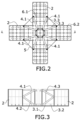
- Figures 1 to 3 show an embodiment of a floating concrete structure for offshore applications, which comprises a semi-submersible platform which in turn comprises:
- the floating structure comprises a pontoon (3), the inner column (1) and the plurality of outer columns (2) being located on the pontoon (3).
- the pontoon (3) comprises a lower base (3.1) and an upper base (3.2).
- the inner column (1) and the plurality of outer columns (2) being located on the lower base (3.1) of the pontoon (3).
- the second beams (4.2) extend between the point of attachment of the third beam (4.3) with each outer column (2) and an area of the pontoon (3) that is annexed to the inner column (1).
- each outer column (2) comprises two first beams (4.1), two second beams (4.2) and two third beams (4.3) distributed symmetrically in each outer column (2) with respect to a plane of symmetry.
- the beam system (4) can be built in concrete and/or steel. In the case of the combination of both, they are made to work together against cyclical traction-compression forces generated by dynamic actions.
- the outer columns (2) can include liquid or mobile (water) and/or solid or fixed ballast inside with the aim of optimising hydrostatic and hydrodynamic behaviour, while the inner column (1) houses the systems required for the management of said mobile ballast.
- the width of each branch of the pontoon (3) is equal to the width of each outer column (2).
- the width of each branch of the pontoon (3) allows the hydrodynamic response of the platform as a whole to be adjusted and is a unique feature of the platform, since it gives it flexibility to be adapted to the different meteorological and oceanic calculation conditions. It facilitates transmission of forces from the inner column (1) to the pontoon (3), allows the draught to be reduced, limits the need for widenings or adjacent plates (5) or heave plates.
- it allows its hydrodynamic response across the width of the pontoon (3) to be adjusted.
- each outer column (2) of figures 1 to 3 comprises a quadrangular cross section.
- each of the symmetrical beams (4) extends up to the vicinity of a vertex of the quadrangular structure of the outer columns (2). Therefore, the outer columns (2) are parallelepipeds.
- the advantage of this configuration is that the beams (4) rest on respective walls of the outer column (2), achieving a robust distribution of loads of the beams (4), that is, of the loads transmitted by the tower and the wind turbine, to the outer columns (2).
- the structure comprises four outer columns (2) such that the lower pontoon (3) comprises a cross-shaped structure with four branches.
- the cross-shaped arrangement of the outer columns (2) allows a perfect distribution of weights and loads to be carried out wherein the inner column (1) and the system of beams (4) and posts are intended to absorb the weight of the tower and wind turbine, as well as the same thrust of the turbine operation.
- the cross-shaped arrangement equips the platform with multiple planes of symmetry that allow the design, in relation to the most common triangular plan designs, to offer a more predictable behaviour at sea regardless of the predominant direction or sector of incidence of environmental forces.
- the symmetrical configuration in the main planes of the structure facilitates its construction and the design of the movement operations of the platform in the manufacturing and transfer area to start the transport. This feature also makes float operations simpler.
- the structure object of the invention further comprises an anchoring system comprising a plurality of lines configured to be anchored to the segment with the greatest resistance, such as the base of each outer column (2) or the upper cover of the outer column (2) or an intermediate segment that optimises the structural and hydrodynamic response of the platform.
- an anchoring system comprising a plurality of lines configured to be anchored to the segment with the greatest resistance, such as the base of each outer column (2) or the upper cover of the outer column (2) or an intermediate segment that optimises the structural and hydrodynamic response of the platform.
- the inner column (1) of figures 1 to 3 has at least one tower, a nacelle, a rotor and a plurality of blades mounted therein.
- the inner column (1) has a hexagonal cross section.
- the walls of the outer columns (2) are internally stiffened by means of ribs (6.2) or partitions (6.1) in the shape of a grid, which allows the thickness of the outer walls to be efficiently reduced.
- the distance between each outer column (2) and the inner column (1) is approximately 3 ⁇ 4 the base of the outer column (2).
- the thickness of the pontoon (3) between the lower base (3.1) and the upper base (3.2) is approximately 10% of the height of each outer column (2).
- the semi-submersible platform further comprises an extension of a lower adjacent plate (5) which can protrude from the pontoon (3) on which the inner (1) and outer (2) columns are fixed by way of a heave plate, which suitably configured can be used to optimise the hydrodynamic response of the structure.
- a lower adjacent plate (5) is made of reinforced concrete.
- the adjacent plate (5) protrudes horizontally from the perimeter of the lower segment of the platform, being therefore projected from the outer columns (2) and the pontoon (3).
- Figure 2 shows another embodiment of the adjacent plate (5) which also consists of a projection of the pontoon (3) in its intersection segment which extends in a triangular shape between the different inner walls and partitions of the branches (3.3) of the pontoon (3).
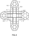
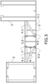
- the inner column (1) and the plurality of beams (4) are located between the lower base (3.1) and the upper base (3.2) of the pontoon (3) unlike figures 1 to 3 wherein the plurality of beams (4) are located outside the pontoon (3) and the inner column (1), and the plurality of outer columns (2) also extend over the upper base (3.2) of the pontoon (3).
- the inner column (1) is limited in height by the upper slab (3.1) of the pontoon (3).
- the inner column (1) is formed by partitions (6.1) of the pontoon (3) that cross each other. In the embodiment shown, the crossing of the partitions (6.1) forms an inner column (1) with a square cross section. In the embodiment shown, the inner column (1) has a square cross section.
- the embodiment of figures 4 and 5 also comprises second beams (4.2) which in this case extend between the point of attachment of the first beam (4.1) with the outer column (2) to an area of the inner column (1) in the area thereof that is annexed to the lower base (3.1) of the pontoon (3).
- the first beams (4.1) can be a rib (6.2) of the upper base (3.2) of the pontoon (3).
Landscapes
- Physics & Mathematics (AREA)
- Fluid Mechanics (AREA)
- Chemical & Material Sciences (AREA)
- Engineering & Computer Science (AREA)
- Combustion & Propulsion (AREA)
- Mechanical Engineering (AREA)
- Ocean & Marine Engineering (AREA)
- Bridges Or Land Bridges (AREA)
Priority Applications (3)
| Application Number | Priority Date | Filing Date | Title |
|---|---|---|---|
| EP23382228.7A EP4428026A1 (de) | 2023-03-10 | 2023-03-10 | Schwimmende betonstruktur für offshore-windanwendungen und verfahren zur herstellung solch einer schwimmenden struktur |
| PCT/EP2024/056224 WO2024188878A1 (en) | 2023-03-10 | 2024-03-08 | Floating concrete structure for offshore wind applications and method for manufacturing said floating structure |
| AU2024237151A AU2024237151A1 (en) | 2023-03-10 | 2024-03-08 | Floating concrete structure for offshore wind applications and method for manufacturing said floating structure |
Applications Claiming Priority (1)
| Application Number | Priority Date | Filing Date | Title |
|---|---|---|---|
| EP23382228.7A EP4428026A1 (de) | 2023-03-10 | 2023-03-10 | Schwimmende betonstruktur für offshore-windanwendungen und verfahren zur herstellung solch einer schwimmenden struktur |
Publications (1)
| Publication Number | Publication Date |
|---|---|
| EP4428026A1 true EP4428026A1 (de) | 2024-09-11 |
Family
ID=86328830
Family Applications (1)
| Application Number | Title | Priority Date | Filing Date |
|---|---|---|---|
| EP23382228.7A Pending EP4428026A1 (de) | 2023-03-10 | 2023-03-10 | Schwimmende betonstruktur für offshore-windanwendungen und verfahren zur herstellung solch einer schwimmenden struktur |
Country Status (3)
| Country | Link |
|---|---|
| EP (1) | EP4428026A1 (de) |
| AU (1) | AU2024237151A1 (de) |
| WO (1) | WO2024188878A1 (de) |
Citations (5)
| Publication number | Priority date | Publication date | Assignee | Title |
|---|---|---|---|---|
| WO2013155521A1 (en) * | 2012-04-13 | 2013-10-17 | University Of Main System Board Of Trustees | Floating wind turbine platform and method of assembling |
| ES2387232B2 (es) | 2012-07-18 | 2014-02-10 | Universidad De Cantabria | Plataforma semisumergible para aplicaciones en mar abierto |
| ES2387342B2 (es) | 2012-07-18 | 2014-02-10 | Universidad De Cantabria | Plataforma semisumergible triángular para aplicaciones en mar abierto |
| WO2015120227A1 (en) * | 2014-02-06 | 2015-08-13 | University Of Maine System Board Of Trustees | Method of assembling a floating wind turbine platform |
| WO2020136288A1 (es) | 2018-12-28 | 2020-07-02 | Dragados, S.A. (45,84%) | Plataforma flotante para aerogeneradores de gran potencia |
-
2023
- 2023-03-10 EP EP23382228.7A patent/EP4428026A1/de active Pending
-
2024
- 2024-03-08 AU AU2024237151A patent/AU2024237151A1/en active Pending
- 2024-03-08 WO PCT/EP2024/056224 patent/WO2024188878A1/en not_active Ceased
Patent Citations (6)
| Publication number | Priority date | Publication date | Assignee | Title |
|---|---|---|---|---|
| WO2013155521A1 (en) * | 2012-04-13 | 2013-10-17 | University Of Main System Board Of Trustees | Floating wind turbine platform and method of assembling |
| ES2387232B2 (es) | 2012-07-18 | 2014-02-10 | Universidad De Cantabria | Plataforma semisumergible para aplicaciones en mar abierto |
| ES2387342B2 (es) | 2012-07-18 | 2014-02-10 | Universidad De Cantabria | Plataforma semisumergible triángular para aplicaciones en mar abierto |
| WO2015120227A1 (en) * | 2014-02-06 | 2015-08-13 | University Of Maine System Board Of Trustees | Method of assembling a floating wind turbine platform |
| WO2020136288A1 (es) | 2018-12-28 | 2020-07-02 | Dragados, S.A. (45,84%) | Plataforma flotante para aerogeneradores de gran potencia |
| EP3904674A1 (de) * | 2018-12-28 | 2021-11-03 | Dragados, S.A. | Schwimmende plattform für hochleistungswindturbinen |
Also Published As
| Publication number | Publication date |
|---|---|
| WO2024188878A1 (en) | 2024-09-19 |
| AU2024237151A1 (en) | 2025-09-25 |
Similar Documents
| Publication | Publication Date | Title |
|---|---|---|
| CN110382781B (zh) | 用于在海洋环境中利用重力铺设建筑物、设备和风力涡轮机的基础的海事结构 | |
| KR102027445B1 (ko) | 해안 풍력 터빈의 지지를 위한 워터-엔트랩먼트 플레이트 및 비대칭 무링 시스템을 가진 칼럼-안정화된 해안 플랫폼 | |
| EP3115600B1 (de) | Schwimmende windturbinenbasis mit festen brennstäben, offshore-windturbine und konstruktionsverfahren | |
| ES2387342B2 (es) | Plataforma semisumergible triángular para aplicaciones en mar abierto | |
| US11920559B2 (en) | Floating platform for high-power wind turbines | |
| EP2789847B1 (de) | Schwimmende windkraftanlage und installationsverfahren dafür | |
| CN112009634A (zh) | 在近海设施中的可潜的主动式支撑结构 | |
| CN112523969A (zh) | 一种桁架拉索型漂浮式海上风电机组结构 | |
| CN202295236U (zh) | 浮式海上风电平台 | |
| ES2387232B2 (es) | Plataforma semisumergible para aplicaciones en mar abierto | |
| EP3276086A1 (de) | Schwerkraftfundament zur installation von offshore-windturbinen | |
| US12313034B2 (en) | Floating reinforced concrete platform applicable to the marine wind power sector industry | |
| CN113306671A (zh) | 一种漂浮式海上风机系统 | |
| KR20230082630A (ko) | 트리 칼럼 반잠수식 해상 부유 플랫폼 | |
| JP2026503659A (ja) | 洋上風力タービン用の半潜水型浮体およびそのような浮体を構築する方法 | |
| JP2024537245A (ja) | 洋上風力タービン用の半潜水型浮体式プラットフォーム | |
| EP4428026A1 (de) | Schwimmende betonstruktur für offshore-windanwendungen und verfahren zur herstellung solch einer schwimmenden struktur | |
| US20240174329A1 (en) | Method of constructing and launching an offshore semi-submersible platform and an offshore semi-submersible platform thus constructed | |
| EP4563814A1 (de) | Halbtauchende plattform zur unterstützung von windturbinen | |
| AU2024351711A1 (en) | Method for the active and individualised ballasting of a semi-submersible float for an offshore wind turbine and float | |
| Jiménez Vicaría | Upscaling of a TLP concrete floating foundation and the challenges for the supply chain under Norwegian offshore wind targets | |
| AU2024353216A1 (en) | Method for active and centralised ballasting of a semi-submersible float for an offshore wind turbine and float | |
| KR20240176120A (ko) | 부유식 풍력 발전기 | |
| Pratt | Floating wind turbines | |
| KR20150033339A (ko) | 풍력발전해양구조물의 상호 연결을 통한 해상풍력발전단지 조성방법 |
Legal Events
| Date | Code | Title | Description |
|---|---|---|---|
| PUAI | Public reference made under article 153(3) epc to a published international application that has entered the european phase |
Free format text: ORIGINAL CODE: 0009012 |
|
| STAA | Information on the status of an ep patent application or granted ep patent |
Free format text: STATUS: THE APPLICATION HAS BEEN PUBLISHED |
|
| AK | Designated contracting states |
Kind code of ref document: A1 Designated state(s): AL AT BE BG CH CY CZ DE DK EE ES FI FR GB GR HR HU IE IS IT LI LT LU LV MC ME MK MT NL NO PL PT RO RS SE SI SK SM TR |
|
| STAA | Information on the status of an ep patent application or granted ep patent |
Free format text: STATUS: REQUEST FOR EXAMINATION WAS MADE |
|
| 17P | Request for examination filed |
Effective date: 20250213 |