EP4428034A2 - Guidage latéral et pont de chargement d'un aéronef - Google Patents
Guidage latéral et pont de chargement d'un aéronef Download PDFInfo
- Publication number
- EP4428034A2 EP4428034A2 EP24191886.1A EP24191886A EP4428034A2 EP 4428034 A2 EP4428034 A2 EP 4428034A2 EP 24191886 A EP24191886 A EP 24191886A EP 4428034 A2 EP4428034 A2 EP 4428034A2
- Authority
- EP
- European Patent Office
- Prior art keywords
- side guide
- fixing
- longitudinal direction
- contour
- fastening frame
- Prior art date
- Legal status (The legal status is an assumption and is not a legal conclusion. Google has not performed a legal analysis and makes no representation as to the accuracy of the status listed.)
- Granted
Links
Images


Classifications
-
- B—PERFORMING OPERATIONS; TRANSPORTING
- B64—AIRCRAFT; AVIATION; COSMONAUTICS
- B64C—AEROPLANES; HELICOPTERS
- B64C1/00—Fuselages; Constructional features common to fuselages, wings, stabilising surfaces or the like
- B64C1/18—Floors
- B64C1/20—Floors specially adapted for freight
-
- B—PERFORMING OPERATIONS; TRANSPORTING
- B64—AIRCRAFT; AVIATION; COSMONAUTICS
- B64D—EQUIPMENT FOR FITTING IN OR TO AIRCRAFT; FLIGHT SUITS; PARACHUTES; ARRANGEMENT OR MOUNTING OF POWER PLANTS OR PROPULSION TRANSMISSIONS IN AIRCRAFT
- B64D9/00—Equipment for handling freight; Equipment for facilitating passenger embarkation or the like
- B64D9/003—Devices for retaining pallets or freight containers
-
- B—PERFORMING OPERATIONS; TRANSPORTING
- B64—AIRCRAFT; AVIATION; COSMONAUTICS
- B64D—EQUIPMENT FOR FITTING IN OR TO AIRCRAFT; FLIGHT SUITS; PARACHUTES; ARRANGEMENT OR MOUNTING OF POWER PLANTS OR PROPULSION TRANSMISSIONS IN AIRCRAFT
- B64D9/00—Equipment for handling freight; Equipment for facilitating passenger embarkation or the like
- B64D2009/006—Rollers or drives for pallets of freight containers, e.g. PDU
Definitions
- the invention relates to a side guide and a cargo deck of an aircraft.
- a side guide according to the preamble of claim 1 is made, for example, from EN 10 2019 124 312 A1 known.
- aircraft cargo holds are often converted for different purposes. For example, it may be necessary to configure a cargo deck depending on the cargo to be loaded.
- cargo items such as containers or pallets with standardized dimensions are often used.
- containers for example for civil aviation, the following standard sizes exist: 123.5 cm by 317.5 cm (88 inches x 125 inches), 143.8 cm by 317.5 cm (96 inches x 125 inches), 223.5 cm by 157.5 cm (88 inches x 62 inches).
- pallets with dimensions of 274.3 cm by 223.5 cm (108 inches x 88 inches) are often used.
- containers are also used which deviate from the usual standards and have retaining rings on the corners so that they can be lifted with a crane, for example.
- Such containers are called ISU containers. They essentially have the following floor dimensions: 274.3 cm by 223.5 cm (108 inches by 88 inches). Their height is approximately 232 cm (91.35 inches).
- side guides mounted on the cargo deck are used.
- Suitable side guides must therefore be quick and easy to attach and reconfigure, as the costs of operating such aircraft are very high.
- the configuration or conversion should be very easy to carry out, as the personnel carrying out this reconfiguration often have little or no training in the cargo decks used.
- the equipment of the cargo deck, especially the side guides must be very robust, as they are exposed to very high loads and gentle treatment cannot be required due to the high time pressure during loading and unloading.
- a cargo deck with corresponding side guides is often exposed to moisture, high temperature differences, dust and other harsh influences.
- a defective cargo deck, or even a defective functional element of the cargo deck can mean that the aircraft in question cannot be used for several days. Such a failure is very expensive.
- the side guides are EN 10 2019 124 312 A1
- Tensile or compressive forces acting transversely on the side guide rail are transferred indirectly, ie via the screw connections of the insert plates, from the rail to the fastening frame.
- horizontal forces acting in the y-direction towards or away from the center of the aircraft always pass through the screw connections between the insert plates and the side guide rail. This causes high bending stresses in the insert plates.
- the screw connections between the insert plates and the side guide rail can fail under such high forces.
- the invention is based on the object of specifying a lateral guide that allows a large number of different configurations, is robust and has increased operational reliability. Furthermore, the invention is based on the object of specifying a cargo deck of an aircraft.
- this object is achieved with regard to the lateral guidance by the subject matter of claim 1.
- the above-mentioned object is achieved by the subject matter of claim 15.
- a side guide for guiding and/or securing cargo items, in particular containers and/or pallets, in an aircraft, which has at least one side guide device and at least one holding unit for the side guide device.
- the holding unit comprises a fastening frame extending in the longitudinal direction and at least one fixing device arranged on the fastening frame, which has a plurality of recesses extending transversely to the longitudinal direction.
- the side guide device can be inserted into at least one of the recesses at different positions and, when inserted, can be secured in the different positions by the fixing device.
- the side guide device has at least one contact element which, when inserted, can be brought into engagement with or is in engagement with at least one fixing element of the fixing device which can be displaced in the longitudinal direction.
- the fixing device is arranged in the fastening frame so as to be displaceable in the longitudinal direction and at least one spring element is provided, which is arranged to support the fastening frame and which spring-loadedly supports the fixing device in the longitudinal direction.
- wing pinching load cases often occur, in which the aircraft's wings move upwards due to high wind loads, thereby deforming the aircraft structure of the cargo deck in the y-direction towards the center of the aircraft.
- side guides for pallets and containers in the cargo hold move inwards and reduce the overall track width for the pallets and containers. This can lead to lateral crushing of the containers and pallets, so that unacceptably high forces act on the aircraft structure.
- the spring-loaded mounting of the securing device and thus of the lateral guide device prevents or at least reduces such additional loads on the aircraft structure caused by increased transverse forces. It is possible to design the lateral guide device to be spring-loaded in several positions when lateral guides are arranged in the cargo hold and require different positions in the y-direction.
- the lateral guide preferably has at least two spring elements that spring-load the securing device in the longitudinal direction on the fastening frame.
- the spring element is preferably arranged in a fork shape.
- the fixing device is preferably arranged in a guided manner in the fastening frame so that an offset in the longitudinal direction can be achieved. This has the advantage that fuselage deformations caused by flight operations and the associated offset of the side guide in the y-direction, particularly in the area of the aircraft's center wing box, prevent the containers and/or pallets from being crushed.
- the side guide device compensates for offsets in the aircraft's y-direction thanks to the movable fixing device.
- Side guides in aircraft are usually used to guide cargo in the longitudinal direction (X-axis) of the aircraft (from nose to tail, or from tail to nose). During flight, these absorb forces transverse to the longitudinal direction (Y-axis) and hold the cargo in position.
- the guide rollers grip the cargo from below and support it. They enable easy and low-friction transport of cargo items within the cargo hold.
- a key idea of the present invention is that the side guide device, which performs the actual guiding and holding function of the side guide in relation to the cargo items, is mounted displaceably in a fastening frame.
- the side guide device can therefore preferably assume different positions in the transverse direction of the aircraft (y-axis) in order to hold and guide cargo items with different dimensions, including standardized cargo items as described in the introduction.
- the recesses can, for example, be slots that are open at the top.
- the recesses enable a positive connection with the insertable side guide device so that forces can be efficiently dissipated.
- the fixing element can perform a rotational and/or translational movement.
- An actuating lever is preferably provided on the fixing element for this purpose.
- the actuating lever and/or the frame has a link, so that the fixing element is displaced in the longitudinal direction of the side guide by actuating the actuating lever.
- the fixing element is preferably formed by a shaft with a longitudinal axis.
- the side guide device has latches. These can be conventionally standardized latches that, by means of their latch noses, grip the edge areas of freight pallets and/or freight containers in order to guide them in the Z direction of the Aircraft. Alternatively or additionally, latches can be provided which engage in corresponding recesses in cargo pallets and/or cargo containers and secure them in the X direction and/or Z direction of the aircraft. Corresponding recesses are often provided in military pallets. Corresponding latches for such military pallets are referred to below as "side latches".
- the side guide device can therefore have one or more such latches, with the side guide device in one embodiment extending over several holding units. If the side guide device extends over several side guides, there is sufficient space to arrange several latches on or at it.
- the side guide according to the invention in such a way that the fastening frame of the side guide extends obliquely to the transverse direction of the aircraft.
- the longitudinal direction of the fastening frame can run at a 45° angle to the transverse direction of the aircraft.
- the fastening frame runs parallel to the transverse direction (Y-axis) of the aircraft.
- the side guide device can be fixed to the fastening frame at at least two different positions by the fixing device. Preferably, however, the side guide device can be fixed at a plurality of positions so that it can interact with the cargo items in different configurations of the cargo deck.
- the at least one contact element has at least one inner support section for the fixing device for introducing forces that occur. Additionally or alternatively, the contact element preferably has at least one form-fitting section with at least one opening with a cross-sectional contour deviating from a circular shape for the engagement of the fixing element.
- the contact element preferably forms a central element which, together with the inner support section and the form-fitting section, fulfils essential functions.
- the inner support section serves to transfer transverse forces occurring in the transverse direction (y-direction) of the aircraft on the lateral guidance device to the fixing device, which is connected to the fastening frame.
- the transverse forces are introduced into the fixing device via the inner support section, which in turn absorbs the introduced Forces are transferred to the fastening frame, which is preferably attached to an aircraft structure.
- the transverse forces are preferably transferred between the inner support section of the contact element and the fixing device directly, ie without an intermediate element.
- an indirect force transfer is also possible.
- the transverse forces are preferably always transmitted under pressure from the contact element to the fixing device, regardless of whether they are tensile and/or compressive forces.
- the support section not only serves to transmit the transverse forces under pressure to the fixing device, but also to absorb the transverse forces under pressure.
- the support section is preferably designed to absorb the transverse forces (tensile and/or compressive forces) acting on the lateral guide device, in particular on a lateral guide rail, under pressure and to transmit them under pressure to the fixing device.
- the inner support section is to be understood as meaning that the support section is formed on an inner side of the contact element, which is arranged at least partially integrated in an interior of the lateral guide device, in particular in a lateral guide rail.
- the inner support section can be flat. Additionally or alternatively, the inner support section can be stepped. Other shapes of the inner support section are possible.
- the form-fitting section is part of the contact element and comprises an opening into which the fixing element engages to fix the lateral guide device in the inserted state.
- the lateral guide device is fixed by the form-fitting between the Fixing element and the form-fitting section in the z-direction.
- the opening has a cross-sectional contour that deviates from a circular shape. In other words, the opening has a shape that deviates from a cylindrical shape. The opening therefore does not correspond to a circular hole.
- the opening shape described has the advantage that when the side guide device, in particular the side guide rail, is subjected to torsion around its longitudinal axis, no increased wedging effect occurs due to the contact element and the fixing element wedging at the opening.
- the opening shape described enables a stable and firm connection to the fixing element, so that inadmissible bending forces are prevented, in particular in the area of a transition to an adjacent release contour of the fixing element. This further increases the operational reliability of the side guide, since the opening shape prevents the positive connection between the fixing element and the positive connection section from coming loose. Furthermore, when the side guide is used in a cargo hold, cargo items with increased weight are transported or secured.
- the fixing element has at least one fixing contour with which the fixing element in a fixing position positively engages the cross-sectional contour of the opening for securing the lateral guide device.
- the lateral guide device is in the inserted state, i.e. it is inserted into at least one of the recesses.
- the fixing contour can be designed to complement the cross-sectional contour of the opening.
- the fixing contour can be a positive shape to the cross-sectional contour of the opening as a negative shape.
- the fixing contour In the fixing position, the fixing contour is in engagement with the cross-sectional contour.
- the fixing contour can be displaceably applied to the cross-sectional contour in the longitudinal direction of the fastening frame. The positive connection between the fixing contour and the cross-sectional contour ensures that the lateral guide device is securely fixed in the corresponding inserted position.
- the fixing contour of the fixing element and/or the cross-sectional contour of the opening have at least one at least partially circular contour section and at least one straight contour section.
- the fixing contour and/or the cross-sectional contour is formed by at least one circular and one straight contour section.
- the fixing contour and/or the cross-sectional contour preferably has a plurality of straight contour sections.
- the straight contour sections are preferably formed by flattenings.
- the flattenings are preferably produced by milling.
- the fixing contour and/or the cross-sectional contour are particularly preferably mushroom-shaped.
- the cross-sectional contour of the opening is preferably designed to be upright in relation to the longitudinal direction of the fastening frame. This also applies to the fixing contour of the fixing element, at least in the fixing position. In this embodiment, a particularly stable form-fitting connection is created, which prevents the contact element and thus the lateral guide device from becoming detached from the fixing element.
- the fixing element further preferably has at least one release contour with at least one flattened portion which adjoins the fixing contour in the longitudinal direction and is designed such that the lateral guide device can be inserted into or removed from at least one of the recesses in a release position of the fixing element.
- the release contour preferably comprises at least two flattened portions lying opposite one another on a longitudinal axis.
- the fixing contour and the release contour preferably each have a flattened portion which continuously merges into the adjacent one.
- the flattened portions which are particularly adjacent to one another are particularly preferably aligned.
- the flattened release contour which adjoins the fixing contour creates a transition between the contours which has an increased residual cross-section compared to a transition between two cylindrical contours. This increases the rigidity of the fixing element, particularly in the transition, and thus reduces or prevents a wedge effect on the opening cross-section of the contact element.
- the contact element is preferably formed by a plate-shaped reinforcing insert, in particular a steel insert plate, which is firmly connected to a rail element of the lateral guide device.
- the rail element preferably has a circumferentially closed profile, in particular a polygonal profile, which has a recess, in particular a milled recess, at least in one position for the contact element.
- the reinforcing insert which preferably firmly connected to the side guide rail of the side guide device, in particular by at least one screw connection.
- the fixing device engages with at least a first housing area in the inserted state in a rail element, in particular the side guide rail, of the side guide device.
- the first housing area comprises at least one stop for the support section of the contact element in the longitudinal direction in order to absorb forces occurring from the rail element.
- the stop of the first housing part and at least a first part of the support section are in contact in the event of a load. If transverse forces occur, these are preferably transferred directly from the support section to the stop. It is advantageous here that the force is always transmitted under pressure and thus any fastening means of the contact element are protected.
- the recesses are preferably provided on the fixing device in such a way that the lateral guide device can be fixed in at least two recesses opposite one another on the first housing region.
- the fixing device has at least a second housing area which is spaced from the contact element when the side guide device is inserted and which, together with the first housing area, delimits at least one of the recesses in at least one of the different positions.
- a first housing area and an opposite second housing area each delimit one of the recesses in the longitudinal direction of the fastening frame.
- the two housing areas are spaced apart from one another in the longitudinal direction so that one of the recesses lies between them and thus forms a gap.
- the distance between the second housing area and the contact element ensures that in the event of a load, transverse forces are always transmitted to the first housing area via the inner support section. This is essential to ensure that the force flow of the transverse forces is not directed via the fastening means of the contact element, but via the inner support section.
- the support section comprises at least one step with which a rail element, in particular the side guide rail, the side guide device is in contact in order to transfer the forces that occur, in particular tensile and compressive forces, in the longitudinal direction of the fastening frame to the fixing device.
- the step forms the second part of the support section.
- the step preferably faces one leg of the rail element.
- the step is formed on the side of the contact element facing away from the stop of the first housing area of the fixing device.
- the step forms a seat for the rail element with which the rail element is in contact. This can be a direct or indirect contact.
- the rail element is supported on the contact element via the step, so that in the event of a load, transverse forces (in the y direction) are specifically absorbed.
- the support section preferably has at least one internal contact surface that faces the first housing part for contact.
- the contact surface faces the stop of the first housing area.
- the internal contact surface of the support section is in contact with the first housing section, preferably directly.
- the stop and the contact surface can alternatively be in contact indirectly.
- the flat contact surface enables flat contact with the stop of the first housing area, whereby the forces are optimally introduced into the fixing device.
- the fixing device is arranged in the fastening frame so that it can be moved in the longitudinal direction.
- the fixing device is arranged so that it can move in the longitudinal direction, in particular so that it floats.
- a carriage which comprises the housing areas and the fixing element mounted therein can be displaced together in the longitudinal direction.
- the side guide has at least one latch with a latch claw that is at least partially split in two and is attached to the fastening frame in such a way that the split latch claw can be pivoted from a raised working position into a lowered rest position.
- the latch claw can comprise a stop that can be pivoted with the latch claw from a raised working position into a lowered rest position.
- the latch claw can be lowered so that it can be driven over by freight items, in particular containers and/or pallets. Further configurations of the cargo deck can be ensured in which the latch takes on the function of guiding and/or holding the cargo items. Due to the latch being able to be folded down, a configuration of the cargo deck can be created that does not provide any additional guidance to the side guide device and can, for example, be driven over by a vehicle.
- the latch can be attached to the fastening frame so that it can rotate about a pivot axis, with the pivot axis being arranged in such a way that forces that occur when holding cargo items are directed into the fastening frame.
- the pivot axis acts as a swivel joint and at the same time efficiently directs the forces that occur into the fastening frame in the working position.
- the locking claw of the latch may have inclined surfaces on at least one side in order to move it from the working position to the rest position when a piece of freight passes over it in a direction that is different from a holding direction of the locking claw.
- the two-part locking claw saves installation space, allowing installation in combination with the fixing element. Furthermore, the two-part design of the locking claw allows so-called "B-Code Military" pallets to be held. These have pallet edges that are interrupted in sections with recesses that are approx. 7 cm (2.75 inches) wide.
- the fork-shaped locking claw secures or holds the freight regardless of the final transport position of the pallets. This improves the usability of the side guide for "B-Code Military" pallets.
- the latch is attached to the fastening frame in such a way that the latch claw of the latch can be pivoted from a working position into a reset parking position.
- the latch claw In the parking position, the latch claw is tilted in the direction facing away from a longitudinal end of the fastening frame.
- the latch claw In the parking position, the latch claw is held in place.
- at least one movable jaw piece can be arranged on or in the fastening frame, which fixes the latch claw.
- space is created in front of it in such a way that the side guide device or the rail element can be fixed in a forward position. As a result, The collision of the locking claw with the side guide device is prevented during placement.
- the fixing element can have a region flattened in the longitudinal direction for receiving a bridge element of the two-part locking claw that runs transversely to the longitudinal direction.
- the bridge element preferably extends transversely to the longitudinal direction of the fastening frame and connects the two claw extensions of the locking claw. In this embodiment, it is advantageous that when driving over or generally when folding down the locking claw, the bridge element is received by the area exposed on the flattened area. This creates a space-saving and compact design.
- the fixing device preferably has at least two of the recesses at one longitudinal end of the fastening frame, with the latch with the two-part latch claw being adjacent on the inside.
- the two-part latch claw is offset from the longitudinal end inwards along the fastening frame in such a way that one of the different positions for the side guide device is provided in the region of the longitudinal end. This further increases the configuration options of a cargo deck.
- the fixing device can comprise at least three, in particular at least four, pairs of recesses, so that the side guide device can be fixed in at least three, in particular four, different positions. It is possible for the fixing device to have at least five pairs of recesses, so that the side guide device can be fixed in five different positions.
- the side guide in this embodiment enables a variety of different configurations, in particular of the cargo deck.
- At least one guide roller is rotatably mounted in a roller housing, which can be inserted or is inserted in at least one of the recesses at different positions.
- This makes it easier to transport the cargo.
- Modern cargo decks are so densely equipped with functional elements (e.g. side guides, guide rollers, locking claws, PDUs) that it is often difficult to find the right place for the necessary functional elements on the cargo deck.
- functional elements e.g. side guides, guide rollers, locking claws, PDUs
- the invention relates to a cargo deck of an aircraft with at least one side guide of the type mentioned above, wherein the side guide has a plurality of holding units to which the side guide device is or can be fixed.
- the cargo deck can alternatively or additionally have individual or a combination of several features previously mentioned in relation to the side guidance.
- a Cartesian coordinate system is usually used to provide individual directional information within an aircraft.
- the X-axis extends from the tail to the nose, the Y-axis runs perpendicular to the X-axis and lies essentially in the plane spanned by the wings.
- the Z-axis is perpendicular to the X- and Y-axes.
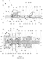
- Fig. 1 to 8 show a side guide 10 according to a preferred embodiment of the invention, wherein the side guide 10 has a side guide device 11 and a holding unit 12 for the side guide device 11.
- the side guide 10 serves to guide and hold or fix cargo items in a cargo deck of an aircraft. Containers and pallets or the like are used as cargo items.
- the side guide device 11 can be fixed to the holding unit 12 at different positions A, B, C, D. This has the advantage that the side guide device 11, which takes on the actual guiding and holding function with respect to the freight items, can be moved along the holding unit 12 and can thus be adapted to the different track widths of the containers or pallets when used in a cargo deck of an aircraft.
- the holding unit 12 comprises a fastening frame 13 which has a longitudinal extension.
- the fastening frame 13 extends in a longitudinal direction v.
- the fastening frame 13 will be discussed in more detail later.
- the holding unit 12 has a fixing device 14 which is arranged on the fastening frame 13 so as to be displaceable in the longitudinal direction v.
- the fixing device 14 is arranged so as to be displaceable in and against the longitudinal direction v.
- the fixing device 14 has a housing 30 which extends along the longitudinal direction v.
- the housing 30 comprises a longitudinal axis L which runs parallel to the longitudinal direction v of the fastening frame 13.
- the housing 30 is arranged on the fastening frame 13 so as to be displaceable in the longitudinal direction v.
- the housing 30 has guide extensions 45 which engage recesses 46 formed in the longitudinal direction of the fastening frame 13.
- the recesses 46 form two T-grooves formed in the longitudinal direction into which the guide extensions 45 engage so as to be longitudinally displaceable.
- the guide extensions 45 are T-shaped and engage in the recesses 46 in such a way that the housing 30 is secured in the Z direction, in particular of the aircraft.
- the housing 30 further comprises a through-bore 47 which penetrates the housing 30 along the longitudinal axis L.
- a fixing element 17 of the fixing device 14 is arranged in the through-bore 47 so as to be longitudinally displaceable in order to fix the lateral guide device 11 at one of the different positions A, B, C, D.
- the fixing element 17 will be discussed in more detail later.
- the housing 30 has several housing areas 31, 33, which are arranged in series along the longitudinal axis L.
- the through hole 47 completely penetrates the housing areas 31, 33.
- the housing 30 is formed in one piece. Alternatively, the housing 30 can be assembled from several individual parts. Two adjacent housing areas 31, 33 are spaced apart from one another along the longitudinal axis L. Between each two adjacent housing areas 31, 33, a recess 15 is formed, which extends to the longitudinal axis L. The recess 15 is formed on both sides of a first of the housing areas 31 in the longitudinal direction v. As in Fig. 2 to 4 As can be seen, the housing 30 comprises a total of four first housing areas 31.
- Each pair of recesses represents one of the different positions A, B, C, D at which the lateral guide device 11 can be fixed.
- a total of seven recesses 15 are formed along the longitudinal axis L.
- the side guide 10 has Fig. 1 to 8 four positions A, B, C, D along the longitudinal axis L, at which the side guide device 11 can be fixed.
- the Fig.1 , 3 , 4 and 6 show, by way of example, the side guide device 11 at the first position A.
- the fixing device 14 comprises a fixing element 17 which is arranged in the housing 30 so as to be displaceable along the longitudinal axis L.
- the fixing element 17 is a fixing shaft which is mounted so as to be longitudinally movable in the through-bore 47 of the housing 30 for fixing and releasing the lateral guide device 11.
- the fixing element 17 is referred to as the fixing shaft with the same reference number.
- the fixing shaft 17 is moved by an actuating lever 48 which has a slotted guide.
- a pin is attached to the fixing shaft 17. This pin engages in the slotted guide of the actuating lever 48, which in turn can be rotated about the fixing shaft 17.
- the rotation of the actuating lever 48 moves the pin in the longitudinal direction v of the fastening frame 13, in particular along the longitudinal axis L of the housing 30, as a result of which the fixing shaft 17 moves in a corresponding translational movement.
- the actuating lever 48 can bring the fixing shaft 17 into a fixing position and a release position. In the fixing position, the fixing shaft 17 fixes the lateral guide device 11 in one of the different positions A, B, C, D. In the release position, the side guide device 11 can be removed from the corresponding pair of recesses and, if required, can be inserted and fixed in another pair of recesses at another position A, B, C, D.
- the fixing shaft 17 has a fixing contour 23 and a release contour 26.
- the two contours 23, 26 adjoin one another in the longitudinal direction v.
- the fixing shaft 17 has a fixing contour 23 and a release contour 26 for each recess 15 of the housing 30.
- the fixing shaft 17 comprises a plurality of fixing and release contours 23, 26 in order to be able to fix the rail element 29 of the side guide device 11 at the positions A, B, C, D.
- the fixing contour 23 of the fixing shaft 17 has a cross-sectional profile deviating from a circular shape.
- Fig.5 shows the fixing shaft 17 in the fixing position, in which the fixing shaft 17 with the fixing contour 23 positively engages in the lateral guide device 11 and locks it.
- the fixing contour 23 of the fixing shaft 17 in the fixing position interacts positively with a cross-sectional contour 22 of an opening 21 of the rail element 29.
- the side guide device 11 For the reception and transmission of high loads, the side guide device 11 according to Fig. 1 to 8 Contact elements 16 which are inserted into the aforementioned rail element 29.
- the contact elements 16 are each formed by a plate-shaped reinforcing insert 28.
- the reinforcing insert 28 is preferably a steel plate.
- two reinforcing inserts 28 are arranged opposite one another on longitudinal legs 49 of the rail element 49.
- the rail element 29 comprises an elongated polygonal profile which is preferably made of aluminum.
- the rail element 29 has recesses on the longitudinal legs 49 into which the reinforcing inserts 28 are inserted.
- the reinforcing inserts 28 are attached to the rail element 29 by several fastening means 51.
- the fastening means 51 are screws in this specific case.
- the screw connection between the respective reinforcing inserts 28 and the rail element 29 are, for example, in Fig.4 clearly visible.
- the rail element 29 is in the inserted and fixed state in the Fig.1 , 3 , 4 and 6 shown.
- the rail element 29 is inserted into the corresponding pair of recesses at position A and is fixed against lifting by the fixing shaft 17.
- the fixing shaft 17 engages with the fixing contour 23 in the opening 21 of a form-fitting section 19 of the respective reinforcement insert 28.
- each of the two opposing reinforcement inserts 28 has an opening 21 which is part of a form-fitting section 19 of the respective reinforcement inserts 28.
- the openings 21 of the two opposing reinforcement inserts 28 are aligned.
- the respective opening 21 has a cross-sectional contour 22 which deviates from a circular shape (see Fig.5 ).
- the cross-sectional contour 22 of the opening 21 and the fixing contour 23 of the fixing shaft 17 are essentially mushroom-shaped. Specifically, the cross-sectional contour 22 of the opening 21 and the fixing contour 23 each have a circular contour section 24 which borders on two straight contour sections 25 lying with respect to the longitudinal axis L. The two lying contour sections 25 each border on a straight contour section 25' standing with respect to the longitudinal axis L.
- the cross-sectional contour 22 of the opening 21 thus comprises two steps due to the straight contour sections 25, 25' on which the fixing contour 23 of the fixing shaft 17 can be or is supported.
- the contour sections of the cross-sectional contour 22 and the fixing contour 23 comprise surfaces that are in contact with one another for fixing.
- a dimensional difference of up to 5% between the cross-sectional contour 22 and the fixing contour 23 can be provided in order to ensure the longitudinal displaceability of the fixing shaft 17.
- the circular contour section 24 is partially cylindrical in the circumferential direction.
- the straight contour sections 25, 25' are flattened areas 27. These are preferably produced by milling the fixing shaft 17.
- the two upright flattened areas 27 of the fixing shaft 17 delimit a web 52 which is orthogonal to the longitudinal axis L and opens into the partially cylindrical part of the fixing contour 23.
- the web 52 has a width transverse to the longitudinal axis L which is smaller than an outer diameter of the fixing shaft 17.
- the web 52 merges into the release contour 26 adjoining the fixing contour 23.
- the web 52 is designed to be upright to the longitudinal axis L over the entire cross section.
- the mushroom-shaped fixing contour 23 adjoins the release contour 26, which is I-shaped.
- Fig.5 it is clearly visible that the opening 21 of the reinforcement inserts 28 is open to the outside, specifically open to the bottom.
- the gap essentially has a width that corresponds to the width of the web 52.
- the rail element 29 can be placed on the release contour 26 in the release position of the fixing shaft 17 and then fixed in the corresponding position by the translational movement of the fixing shaft 17 over the fixing contour 23.
- the fixing and releasing of the rail element 29 takes place according to the key/hole principle.
- the fixing shaft 17 is in the release position.
- the rail element 29 is pushed onto the release contour 26, in particular the web 52, with the openings 21 in the reinforcement inserts 28 open downwards.
- the rail element 29 and thus the lateral guide device 11 are loosely inserted. If necessary, it can be removed from the pair of recesses in this state and moved to another of the positions.
- the fixing shaft 17 is displaced in the longitudinal direction v so that the fixing contour 23 moves into the opening 21 and forms a positive connection with the cross-sectional contour 22 of the opening 21.
- the positive connection is formed by moving the fixing shaft 17 on both opposing reinforcement inserts 28 by a separate fixing contour 23 of the fixing shaft 17. In this state, the fixing shaft 17 is in the fixing position. The rail element 29 and thus the lateral guide device 11 is fixed and thus secured against lifting.
- the form-fitting section 19 is essentially triangular in shape and comprises an extension 53 which is arranged in the wall of the longitudinal legs 49 of the rail element 29.
- the extension 53 is in contact with the wall of the longitudinal legs 49.
- the opening 21 completely penetrates the extension 53.
- the respective reinforcing insert 28 further comprises a support section 18 which is arranged on an inner side. Specifically, the support section 18 is arranged integrated into the rail element 29. The support section 18 is arranged on the reinforcing insert 28 on a side facing a rail interior 54. The support section 18 forms the plate-shaped part of the reinforcing insert 28. The extension 53 of the form-fitting section 19 extends from the support section 18.
- the support section 18 serves to absorb transverse forces that act on the rail element 29 transversely to the longitudinal direction of the rail, and to introduce the absorbed transverse forces into the housing 30 of the fixing device 14.
- the transfer of forces from the rail element 29 to the housing 30 always takes place under pressure. This means that regardless of whether transverse forces occur on the rail element 29 as tensile forces or compressive forces, they are absorbed under pressure by the reinforcement insert 28 and transferred under pressure from the reinforcement insert 28 to the housing 30, specifically the first housing area 31.
- the support section 18 of the respective reinforcement insert 28 has a step 34 which faces one of the longitudinal legs 49 of the rail element 29.
- the rail element 29 rests against the step 34.
- the longitudinal leg 49 of the rail element 29 rests against a step wall and a step floor, which together form the step 34.
- the support section 18 has a contact surface 35.
- the contact surface 35 faces the rail interior 54 and is therefore arranged on the inside with respect to the rail element 29.
- the contact surface 35 is in contact with the first housing area 31 in the case of a load, in which corresponding transverse forces are absorbed and transmitted.
- the reinforcement insert 28 is pressed against the first housing area 31 with the contact surface 35.
- the contact surface 35 is in direct contact with the first housing area 31 in the case of a load. If no transverse loads occur, i.e. in the non-loading case, the first housing area 31 can be spaced from one or both contact surfaces 35 of the reinforcing inserts 28.
- the housing 30 extends with the first housing area 31 into the rail element 29. Specifically, the housing 30 engages with the first housing area 31 in the rail interior 54 of the rail element 29.
- the first housing area 31 has a stop 32 at both longitudinal ends, which is arranged opposite the contact surface 35 of the respective reinforcement insert 28. In the case of load, the contact surface 35 strikes a stop 32 of the first housing area 31 opposite in each case for the transmission of force.
- the second housing areas 33 or the housing area 31, 33 opposite the first housing area 31 in the longitudinal direction v is spaced apart from the reinforcing insert 28 located in the recess 15 when under load and when not under load.
- the holding unit 12 comprises two spring elements 36, which resiliently support the fixing device 14 in the longitudinal direction v.
- the holding unit 12 comprises two spring elements 36, which resiliently support the fixing device 14 in the longitudinal direction v.
- only one spring element 36 or several spring elements 36 can be provided for resiliently supporting the fixing device 14.
- the spring elements 36 are arranged opposite one another on the longitudinal axis L on the fastening frame 13.
- the fastening frame 13 has a receiving space 55 for each spring element 36, in which the respective spring element 36 is arranged.
- the respective spring element 36 is supported on the one hand on an abutment 56 of the fastening frame 13 and on the other hand is in contact with the housing 30 which can be moved in the longitudinal direction.
- the housing 30 has wing-like contact areas 57, via which the housing 30 is in longitudinally movable contact with the spring elements 36.
- the spring elements 36 are arranged at one longitudinal end of the fastening frame 13.
- the spring elements 36 are V-shaped.
- the ends of the spring elements 36 are in contact with the abutment 56 and the wing-like contact area 57 of the housing 30.
- At an apex of the spring elements 36 these are mounted in a recess in the fastening frame 13, in particular about a stationary axis of rotation.
- the actuating lever 48 is arranged along the longitudinal axis L at the axial position of the spring elements 36.
- one of the four positions for the side guide device 11 is provided at a longitudinal end 42 of the fastening frame 13. This is position D.
- a latch 37 with a latch claw 38 is arranged on the fastening frame 13.
- the latch 37 adjoins the inner recess 15 of the pair of recesses in position D.
- the latch 37 is attached to the fastening frame 13 so that it can rotate about an axis of rotation that is transverse to the longitudinal direction v.
- Two springs 59 in particular spiral springs, are arranged on the axis of rotation, which pre-tension the latch 37 so that it can rotate in a direction facing away from position D (see Fig.3 ).
- jaws 58 which can be moved transversely to the longitudinal direction v are arranged in the fastening frame 13 and which Fig.8 can be seen.
- the jaws 58 are movable between a blocking position and a release position transverse to the longitudinal axis L. In the blocking position, the jaws 58 are in contact with a nose of the latch 37.
- the jaws 58 form a stop for the latch 37 in order to block a rotary movement of the latch 37 about the axis of rotation by the pre-tensioned springs 59.
- the latch 37 In the working position, the latch 37 can perform its guiding and holding function in relation to a piece of cargo.
- the springs 59 pivot the latch 37 into a reset parking position.
- the jaws 58 have a further stop for the parking position, against which the latch 37 rests.
- the latch 37 can be folded down around the rotation axis towards position D. This can be advantageous, for example, when driving over the latch 37.
- the latch 37 can therefore assume a lowered rest position in addition to the parking position.
- the locking claw 38 of the latch 37 is divided into two sections.
- the locking claw 38 is fork-shaped.
- the locking claw 38 has two claw legs 61 running in the longitudinal direction v, which are provided on both sides of the longitudinal axis L.
- the claw legs 61 are spaced apart from one another transversely to the longitudinal direction v.
- the claw legs 61 are preferably spaced apart from one another by 5 cm to 15 cm (approx. 1.95 inches to 5.9 inches), in particular by 5 cm to 10 cm (approx. 1.95 inches to approx. 3.9 inches), preferably by 7 cm (approx. 2.75 inches).
- the claw legs 61 are connected via a bridge element 41.
- the bridge element 41 extends transversely to the longitudinal axis L and connects the two claw legs 61.
- the locking claw 38 is formed in one piece.
- the bridge element 41 extends over the fixing device 14.
- the fixing shaft 17 In order to pivot the locking device 37 into the lowered rest position, the fixing shaft 17 has a flattened area in an upper area. In this area, the housing 30 is exposed so that the bridge element 41 can be accommodated when the locking device 37 is lowered.
- the side guide 10 has a guide unit 40 with two guide rollers 43 and a roller housing 44.
- the guide rollers 43 are arranged in the roller housing 44 so that they can rotate.
- the guide rollers 43 are roller-shaped.
- the roller housing 44 forms a frame which, in the present exemplary embodiment, is inserted into the associated pair of recesses at position C and is fixed by the fixing shaft 17.
- the frame has an opening at the location of each recess 15 which corresponds to the opening 21 of the reinforcing insert 28.
- the guide unit 40 is arranged adjacent to the latch 37. It is possible to insert the guide unit 40 into a pair of recesses at each of the different positions A, B, C, D and to fix it in place by the fixing shaft 17, like the rail element 29.
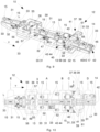
- Fig. 9 to 11 show a holding unit 12 of a side guide 10 according to a further embodiment of the invention.
- the holding unit 12 has an extended fastening frame 13 to allow a further position on the fixing device 14 for the side guide device 11 (not shown).
- the side guide 10 according to Fig. 9 to 11 five positions A, B, C, D, E along the longitudinal axis L, at which the side guide device 11 can be fixed.
- the further position E is provided at a second longitudinal end of the fastening frame 13.
- the fixing device 14 has a further pair of recesses for receiving the rail element 29.
- the fixing shaft 17 additionally has two fixing contours 23 and two release contours 26 at the axial points of the additional recesses 15.
- FIG. 11 The exploded view shown illustrates an example of the side guide 10 according to Fig. 1 to 8 and the side guide 10 according to Fig. 9 to 11 the design of the housing 30 and the fixing shaft 17, in particular with regard to the fixing and release contours.
- the side guide device 11 of the side guides 10 comprises bars arranged on the rail element 29 for holding and/or guiding freight items.
- Such bars can be so-called X-bars and/or Z-bars (see for example Fig.1 or 3 ) and/or Y-bars to guide and secure the cargo items safely.
Landscapes
- Engineering & Computer Science (AREA)
- Aviation & Aerospace Engineering (AREA)
- Mechanical Engineering (AREA)
- Connection Of Plates (AREA)
- Pallets (AREA)
Applications Claiming Priority (2)
| Application Number | Priority Date | Filing Date | Title |
|---|---|---|---|
| DE102021111705.4A DE102021111705A1 (de) | 2021-05-05 | 2021-05-05 | Seitenführung und Frachtdeck eines Flugzeugs |
| EP22171450.4A EP4086164B1 (fr) | 2021-05-05 | 2022-05-03 | Guidage latéral et plateforme de chargement d'un avion |
Related Parent Applications (2)
| Application Number | Title | Priority Date | Filing Date |
|---|---|---|---|
| EP22171450.4A Division-Into EP4086164B1 (fr) | 2021-05-05 | 2022-05-03 | Guidage latéral et plateforme de chargement d'un avion |
| EP22171450.4A Division EP4086164B1 (fr) | 2021-05-05 | 2022-05-03 | Guidage latéral et plateforme de chargement d'un avion |
Publications (3)
| Publication Number | Publication Date |
|---|---|
| EP4428034A2 true EP4428034A2 (fr) | 2024-09-11 |
| EP4428034A3 EP4428034A3 (fr) | 2024-09-25 |
| EP4428034B1 EP4428034B1 (fr) | 2025-11-12 |
Family
ID=81579993
Family Applications (4)
| Application Number | Title | Priority Date | Filing Date |
|---|---|---|---|
| EP24191569.3A Pending EP4428033A3 (fr) | 2021-05-05 | 2022-05-03 | Guidage latéral et pont de chargement d'un aéronef |
| EP22171450.4A Active EP4086164B1 (fr) | 2021-05-05 | 2022-05-03 | Guidage latéral et plateforme de chargement d'un avion |
| EP24192078.4A Active EP4431388B1 (fr) | 2021-05-05 | 2022-05-03 | Guidage latéral et pont de chargement d'un aéronef |
| EP24191886.1A Active EP4428034B1 (fr) | 2021-05-05 | 2022-05-03 | Guidage latéral et pont de chargement d'un aéronef |
Family Applications Before (3)
| Application Number | Title | Priority Date | Filing Date |
|---|---|---|---|
| EP24191569.3A Pending EP4428033A3 (fr) | 2021-05-05 | 2022-05-03 | Guidage latéral et pont de chargement d'un aéronef |
| EP22171450.4A Active EP4086164B1 (fr) | 2021-05-05 | 2022-05-03 | Guidage latéral et plateforme de chargement d'un avion |
| EP24192078.4A Active EP4431388B1 (fr) | 2021-05-05 | 2022-05-03 | Guidage latéral et pont de chargement d'un aéronef |
Country Status (3)
| Country | Link |
|---|---|
| US (1) | US12528585B2 (fr) |
| EP (4) | EP4428033A3 (fr) |
| DE (1) | DE102021111705A1 (fr) |
Families Citing this family (1)
| Publication number | Priority date | Publication date | Assignee | Title |
|---|---|---|---|---|
| USD1063788S1 (en) * | 2023-05-24 | 2025-02-25 | Textron Innovations Inc. | Aircraft sideledge |
Citations (1)
| Publication number | Priority date | Publication date | Assignee | Title |
|---|---|---|---|---|
| DE102019124312A1 (de) | 2019-09-10 | 2021-03-11 | Telair International Gmbh | Seitenführung, Seitenführungsgruppe, Frachtdeck |
Family Cites Families (7)
| Publication number | Priority date | Publication date | Assignee | Title |
|---|---|---|---|---|
| US6002350A (en) | 1999-03-26 | 1999-12-14 | Checa; Humberto | Cargo movement detection system |
| US9540106B2 (en) | 2009-06-22 | 2017-01-10 | Telair International Gmbh | Locking element |
| DE102010017535B4 (de) | 2010-06-23 | 2018-10-25 | Telair International Gmbh | Befestigungseinrichtung zum zumindest teilweisen Sichern eines ersten und eines zweiten Frachtstücks |
| DE102010036983B4 (de) | 2010-08-13 | 2012-05-03 | Telair International Gmbh | Seitenführung, Seitenführungsgruppe, Frachtdeck |
| DE102017128238B3 (de) * | 2017-11-29 | 2018-11-29 | Airbus Operations Gmbh | System zum Bewegen von Lasten in einem Flugzeug |
| DE102018108803B4 (de) * | 2018-03-07 | 2022-04-07 | Telair International Gmbh | Seitenführung, Seitenführungsgruppe, Frachtdeck, Flugzeug |
| US11167848B2 (en) | 2018-03-23 | 2021-11-09 | The Boeing Company | Unmanned aerial vehicle with enhanced cargo storage |
-
2021
- 2021-05-05 DE DE102021111705.4A patent/DE102021111705A1/de active Pending
-
2022
- 2022-05-03 EP EP24191569.3A patent/EP4428033A3/fr active Pending
- 2022-05-03 EP EP22171450.4A patent/EP4086164B1/fr active Active
- 2022-05-03 EP EP24192078.4A patent/EP4431388B1/fr active Active
- 2022-05-03 EP EP24191886.1A patent/EP4428034B1/fr active Active
- 2022-05-04 US US17/736,805 patent/US12528585B2/en active Active
Patent Citations (1)
| Publication number | Priority date | Publication date | Assignee | Title |
|---|---|---|---|---|
| DE102019124312A1 (de) | 2019-09-10 | 2021-03-11 | Telair International Gmbh | Seitenführung, Seitenführungsgruppe, Frachtdeck |
Also Published As
| Publication number | Publication date |
|---|---|
| DE102021111705A1 (de) | 2022-11-10 |
| EP4086164B1 (fr) | 2025-11-12 |
| EP4428034B1 (fr) | 2025-11-12 |
| EP4431388A3 (fr) | 2024-09-25 |
| US20220355933A1 (en) | 2022-11-10 |
| EP4428034A3 (fr) | 2024-09-25 |
| US12528585B2 (en) | 2026-01-20 |
| EP4428033A2 (fr) | 2024-09-11 |
| EP4428033A3 (fr) | 2024-09-25 |
| EP4431388A2 (fr) | 2024-09-18 |
| EP4086164A1 (fr) | 2022-11-09 |
| EP4431388B1 (fr) | 2026-03-18 |
Similar Documents
| Publication | Publication Date | Title |
|---|---|---|
| DE69901443T2 (de) | Herstellungsverfahren einer autokarosserie | |
| EP2548470B1 (fr) | table de laboratoire | |
| EP2418149A2 (fr) | Guidage latéral, groupe de guidage latéral et plafond de soute | |
| EP2445752B1 (fr) | Élément de verrouillage | |
| EP2445791B1 (fr) | Élément fonctionnel et son procédé de production | |
| EP2399826B1 (fr) | Dispositif de fixation pour la fixation au moins partielle d'un premier et d'un second colis | |
| EP1481844B1 (fr) | Système d'arrimage pour cargaison | |
| DE102019124312B4 (de) | Seitenführung, Seitenführungsgruppe, Frachtdeck | |
| EP4086164B1 (fr) | Guidage latéral et plateforme de chargement d'un avion | |
| DE102020122963B4 (de) | Seitenführungsadapter, Seitenführungssystem, Frachtdeck und Verfahren zum Umrüsten eines Frachtdecks | |
| EP3536601B1 (fr) | Guidage latéral, groupe de guidages latéraux, pont cargo, aéronef | |
| EP4086174B1 (fr) | Dispositif de verrouillage et pont de chargement | |
| EP2664540B1 (fr) | Dispositif de verrouillage pour sécuriser et guider au moins un colis | |
| EP3960540B1 (fr) | Adaptateur de guidage latéral, système de guidage latéral, pont à fret et procédé de transformation d'un pont à fret | |
| DE102011116920B4 (de) | Sicherungsvorrichtung für Container zum Sichern großer Behälter | |
| DE102024138939B3 (de) | Schnellanschlusssystem, Flugzeugfrachtraum, Flugzeug und Verfahren zur Umkonfigurierung eines Flugzeugfrachtraums | |
| WO2000021864A1 (fr) | Procede pour fixer un conteneur sur un conteneur situe en dessous ou element de transport | |
| DE9217738U1 (de) | Vorrichtung zum Führen und/oder Arretieren eines entlang einer Führungsschiene verschiebbar und/oder arretierbar angeordneten Gegenstandes | |
| EP0323394A1 (fr) | Méthode de verrouillage d'au moins deux conteneurs ISO pour former une unité de transport ainsi que l'unité de transport | |
| DE102013104539A1 (de) | Palette, Frachtdeck mit einer entsprechenden Palette und Verfahren zum Umrüsten eines Frachtflugzeugs | |
| DE202023105033U1 (de) | Beschlag zum Festlegen von Ladungsstücken an einer Sicherungsschiene | |
| DE102021109257A1 (de) | System aus Riegelelementen und Frachtträgern | |
| EP4488086A1 (fr) | Structure de véhicule utilitaire | |
| DE102020133943A1 (de) | Frachtträger zur Aufnahme in den Frachtbereich eines Flugzeugs mit verfahrbaren Rollelementen | |
| DE10307598A1 (de) | Vorrichtung zur Sicherung von rollenförmigen Ladegütern, insbesondere liegenden Papierrollen auf dem Ladeboden von Fahrzeugen, insbesondere Eisenbahngüterwagen |
Legal Events
| Date | Code | Title | Description |
|---|---|---|---|
| PUAI | Public reference made under article 153(3) epc to a published international application that has entered the european phase |
Free format text: ORIGINAL CODE: 0009012 |
|
| STAA | Information on the status of an ep patent application or granted ep patent |
Free format text: STATUS: THE APPLICATION HAS BEEN PUBLISHED |
|
| REG | Reference to a national code |
Ref country code: DE Ipc: B64C0001200000 Ref country code: DE Ref legal event code: R079 Ref document number: 502022006148 Country of ref document: DE Free format text: PREVIOUS MAIN CLASS: B64D0009000000 Ipc: B64C0001200000 |
|
| PUAL | Search report despatched |
Free format text: ORIGINAL CODE: 0009013 |
|
| AC | Divisional application: reference to earlier application |
Ref document number: 4086164 Country of ref document: EP Kind code of ref document: P |
|
| AK | Designated contracting states |
Kind code of ref document: A2 Designated state(s): AL AT BE BG CH CY CZ DE DK EE ES FI FR GB GR HR HU IE IS IT LI LT LU LV MC MK MT NL NO PL PT RO RS SE SI SK SM TR |
|
| AK | Designated contracting states |
Kind code of ref document: A3 Designated state(s): AL AT BE BG CH CY CZ DE DK EE ES FI FR GB GR HR HU IE IS IT LI LT LU LV MC MK MT NL NO PL PT RO RS SE SI SK SM TR |
|
| RIC1 | Information provided on ipc code assigned before grant |
Ipc: B64D 9/00 20060101ALI20240819BHEP Ipc: B64C 1/20 20060101AFI20240819BHEP |
|
| STAA | Information on the status of an ep patent application or granted ep patent |
Free format text: STATUS: REQUEST FOR EXAMINATION WAS MADE |
|
| 17P | Request for examination filed |
Effective date: 20250212 |
|
| GRAP | Despatch of communication of intention to grant a patent |
Free format text: ORIGINAL CODE: EPIDOSNIGR1 |
|
| STAA | Information on the status of an ep patent application or granted ep patent |
Free format text: STATUS: GRANT OF PATENT IS INTENDED |
|
| INTG | Intention to grant announced |
Effective date: 20250623 |
|
| GRAS | Grant fee paid |
Free format text: ORIGINAL CODE: EPIDOSNIGR3 |
|
| GRAA | (expected) grant |
Free format text: ORIGINAL CODE: 0009210 |
|
| STAA | Information on the status of an ep patent application or granted ep patent |
Free format text: STATUS: THE PATENT HAS BEEN GRANTED |
|
| AC | Divisional application: reference to earlier application |
Ref document number: 4086164 Country of ref document: EP Kind code of ref document: P |
|
| AK | Designated contracting states |
Kind code of ref document: B1 Designated state(s): AL AT BE BG CH CY CZ DE DK EE ES FI FR GB GR HR HU IE IS IT LI LT LU LV MC MK MT NL NO PL PT RO RS SE SI SK SM TR |
|
| REG | Reference to a national code |
Ref country code: CH Ref legal event code: F10 Free format text: ST27 STATUS EVENT CODE: U-0-0-F10-F00 (AS PROVIDED BY THE NATIONAL OFFICE) Effective date: 20251112 Ref country code: GB Ref legal event code: FG4D Free format text: NOT ENGLISH |
|
| REG | Reference to a national code |
Ref country code: DE Ref legal event code: R096 Ref document number: 502022006148 Country of ref document: DE |
|
| REG | Reference to a national code |
Ref country code: IE Ref legal event code: FG4D Free format text: LANGUAGE OF EP DOCUMENT: GERMAN |
|
| REG | Reference to a national code |
Ref country code: NL Ref legal event code: MP Effective date: 20251112 |
|
| PGFP | Annual fee paid to national office [announced via postgrant information from national office to epo] |
Ref country code: GB Payment date: 20260304 Year of fee payment: 5 |
|
| PG25 | Lapsed in a contracting state [announced via postgrant information from national office to epo] |
Ref country code: ES Free format text: LAPSE BECAUSE OF FAILURE TO SUBMIT A TRANSLATION OF THE DESCRIPTION OR TO PAY THE FEE WITHIN THE PRESCRIBED TIME-LIMIT Effective date: 20251112 |
|
| REG | Reference to a national code |
Ref country code: LT Ref legal event code: MG9D |
|
| PG25 | Lapsed in a contracting state [announced via postgrant information from national office to epo] |
Ref country code: NO Free format text: LAPSE BECAUSE OF FAILURE TO SUBMIT A TRANSLATION OF THE DESCRIPTION OR TO PAY THE FEE WITHIN THE PRESCRIBED TIME-LIMIT Effective date: 20260212 |
|
| PG25 | Lapsed in a contracting state [announced via postgrant information from national office to epo] |
Ref country code: FI Free format text: LAPSE BECAUSE OF FAILURE TO SUBMIT A TRANSLATION OF THE DESCRIPTION OR TO PAY THE FEE WITHIN THE PRESCRIBED TIME-LIMIT Effective date: 20251112 Ref country code: HR Free format text: LAPSE BECAUSE OF FAILURE TO SUBMIT A TRANSLATION OF THE DESCRIPTION OR TO PAY THE FEE WITHIN THE PRESCRIBED TIME-LIMIT Effective date: 20251112 |
|
| PG25 | Lapsed in a contracting state [announced via postgrant information from national office to epo] |
Ref country code: NL Free format text: LAPSE BECAUSE OF FAILURE TO SUBMIT A TRANSLATION OF THE DESCRIPTION OR TO PAY THE FEE WITHIN THE PRESCRIBED TIME-LIMIT Effective date: 20251112 |
|
| PG25 | Lapsed in a contracting state [announced via postgrant information from national office to epo] |
Ref country code: RS Free format text: LAPSE BECAUSE OF FAILURE TO SUBMIT A TRANSLATION OF THE DESCRIPTION OR TO PAY THE FEE WITHIN THE PRESCRIBED TIME-LIMIT Effective date: 20260212 |
|
| PG25 | Lapsed in a contracting state [announced via postgrant information from national office to epo] |
Ref country code: IS Free format text: LAPSE BECAUSE OF FAILURE TO SUBMIT A TRANSLATION OF THE DESCRIPTION OR TO PAY THE FEE WITHIN THE PRESCRIBED TIME-LIMIT Effective date: 20260312 |
|
| PG25 | Lapsed in a contracting state [announced via postgrant information from national office to epo] |
Ref country code: PT Free format text: LAPSE BECAUSE OF FAILURE TO SUBMIT A TRANSLATION OF THE DESCRIPTION OR TO PAY THE FEE WITHIN THE PRESCRIBED TIME-LIMIT Effective date: 20260312 |
|
| PG25 | Lapsed in a contracting state [announced via postgrant information from national office to epo] |
Ref country code: PL Free format text: LAPSE BECAUSE OF FAILURE TO SUBMIT A TRANSLATION OF THE DESCRIPTION OR TO PAY THE FEE WITHIN THE PRESCRIBED TIME-LIMIT Effective date: 20251112 |
|
| PG25 | Lapsed in a contracting state [announced via postgrant information from national office to epo] |
Ref country code: LV Free format text: LAPSE BECAUSE OF FAILURE TO SUBMIT A TRANSLATION OF THE DESCRIPTION OR TO PAY THE FEE WITHIN THE PRESCRIBED TIME-LIMIT Effective date: 20251112 |
|
| P01 | Opt-out of the competence of the unified patent court (upc) registered |
Free format text: CASE NUMBER: UPC_APP_0010640_4428034/2026 Effective date: 20260323 |