EP4428045A1 - Outil de liage pour le liage sans déchets d'un matériau de liaison - Google Patents
Outil de liage pour le liage sans déchets d'un matériau de liaison Download PDFInfo
- Publication number
- EP4428045A1 EP4428045A1 EP24158647.8A EP24158647A EP4428045A1 EP 4428045 A1 EP4428045 A1 EP 4428045A1 EP 24158647 A EP24158647 A EP 24158647A EP 4428045 A1 EP4428045 A1 EP 4428045A1
- Authority
- EP
- European Patent Office
- Prior art keywords
- bundling
- pushing
- end section
- unit
- path portion
- Prior art date
- Legal status (The legal status is an assumption and is not a legal conclusion. Google has not performed a legal analysis and makes no representation as to the accuracy of the status listed.)
- Pending
Links
Images
Classifications
-
- B—PERFORMING OPERATIONS; TRANSPORTING
- B65—CONVEYING; PACKING; STORING; HANDLING THIN OR FILAMENTARY MATERIAL
- B65B—MACHINES, APPARATUS OR DEVICES FOR, OR METHODS OF, PACKAGING ARTICLES OR MATERIALS; UNPACKING
- B65B13/00—Bundling articles
- B65B13/02—Applying and securing binding material around articles or groups of articles, e.g. using strings, wires, strips, bands or tapes
- B65B13/04—Applying and securing binding material around articles or groups of articles, e.g. using strings, wires, strips, bands or tapes with means for guiding the binding material around the articles prior to severing from supply
- B65B13/14—Pairs of carriers or guides movable around opposite sides of the articles
-
- B—PERFORMING OPERATIONS; TRANSPORTING
- B65—CONVEYING; PACKING; STORING; HANDLING THIN OR FILAMENTARY MATERIAL
- B65B—MACHINES, APPARATUS OR DEVICES FOR, OR METHODS OF, PACKAGING ARTICLES OR MATERIALS; UNPACKING
- B65B13/00—Bundling articles
- B65B13/02—Applying and securing binding material around articles or groups of articles, e.g. using strings, wires, strips, bands or tapes
- B65B13/025—Hand-held tools
- B65B13/027—Hand-held tools for applying straps having preformed connecting means, e.g. cable ties
-
- B—PERFORMING OPERATIONS; TRANSPORTING
- B65—CONVEYING; PACKING; STORING; HANDLING THIN OR FILAMENTARY MATERIAL
- B65B—MACHINES, APPARATUS OR DEVICES FOR, OR METHODS OF, PACKAGING ARTICLES OR MATERIALS; UNPACKING
- B65B13/00—Bundling articles
- B65B13/02—Applying and securing binding material around articles or groups of articles, e.g. using strings, wires, strips, bands or tapes
- B65B13/04—Applying and securing binding material around articles or groups of articles, e.g. using strings, wires, strips, bands or tapes with means for guiding the binding material around the articles prior to severing from supply
- B65B13/06—Stationary ducts or channels
-
- B—PERFORMING OPERATIONS; TRANSPORTING
- B65—CONVEYING; PACKING; STORING; HANDLING THIN OR FILAMENTARY MATERIAL
- B65B—MACHINES, APPARATUS OR DEVICES FOR, OR METHODS OF, PACKAGING ARTICLES OR MATERIALS; UNPACKING
- B65B13/00—Bundling articles
- B65B13/02—Applying and securing binding material around articles or groups of articles, e.g. using strings, wires, strips, bands or tapes
- B65B13/025—Hand-held tools
-
- B—PERFORMING OPERATIONS; TRANSPORTING
- B65—CONVEYING; PACKING; STORING; HANDLING THIN OR FILAMENTARY MATERIAL
- B65B—MACHINES, APPARATUS OR DEVICES FOR, OR METHODS OF, PACKAGING ARTICLES OR MATERIALS; UNPACKING
- B65B13/00—Bundling articles
- B65B13/18—Details of, or auxiliary devices used in, bundling machines or bundling tools
-
- B—PERFORMING OPERATIONS; TRANSPORTING
- B65—CONVEYING; PACKING; STORING; HANDLING THIN OR FILAMENTARY MATERIAL
- B65B—MACHINES, APPARATUS OR DEVICES FOR, OR METHODS OF, PACKAGING ARTICLES OR MATERIALS; UNPACKING
- B65B13/00—Bundling articles
- B65B13/18—Details of, or auxiliary devices used in, bundling machines or bundling tools
- B65B13/185—Details of tools
-
- B—PERFORMING OPERATIONS; TRANSPORTING
- B65—CONVEYING; PACKING; STORING; HANDLING THIN OR FILAMENTARY MATERIAL
- B65B—MACHINES, APPARATUS OR DEVICES FOR, OR METHODS OF, PACKAGING ARTICLES OR MATERIALS; UNPACKING
- B65B13/00—Bundling articles
- B65B13/18—Details of, or auxiliary devices used in, bundling machines or bundling tools
- B65B13/24—Securing ends of binding material
- B65B13/34—Securing ends of binding material by applying separate securing members, e.g. deformable clips
- B65B13/345—Hand tools
-
- B—PERFORMING OPERATIONS; TRANSPORTING
- B65—CONVEYING; PACKING; STORING; HANDLING THIN OR FILAMENTARY MATERIAL
- B65B—MACHINES, APPARATUS OR DEVICES FOR, OR METHODS OF, PACKAGING ARTICLES OR MATERIALS; UNPACKING
- B65B57/00—Automatic control, checking, warning, or safety devices
- B65B57/02—Automatic control, checking, warning, or safety devices responsive to absence, presence, abnormal feed, or misplacement of binding or wrapping material, containers, or packages
- B65B57/04—Automatic control, checking, warning, or safety devices responsive to absence, presence, abnormal feed, or misplacement of binding or wrapping material, containers, or packages and operating to control, or to stop, the feed of such material, containers, or packages
-
- B—PERFORMING OPERATIONS; TRANSPORTING
- B65—CONVEYING; PACKING; STORING; HANDLING THIN OR FILAMENTARY MATERIAL
- B65B—MACHINES, APPARATUS OR DEVICES FOR, OR METHODS OF, PACKAGING ARTICLES OR MATERIALS; UNPACKING
- B65B61/00—Auxiliary devices, not otherwise provided for, for operating on sheets, blanks, webs, binding material, containers or packages
- B65B61/04—Auxiliary devices, not otherwise provided for, for operating on sheets, blanks, webs, binding material, containers or packages for severing webs, or for separating joined packages
- B65B61/06—Auxiliary devices, not otherwise provided for, for operating on sheets, blanks, webs, binding material, containers or packages for severing webs, or for separating joined packages by cutting
Definitions
- the disclosure relates to a bundling tool for waste-free bundling of a binding material/bundling good by means of an endless strap or strap, comprising an exchangeable jaw unit for guiding an end section of the endless strap around the bundling good, a lock feeding unit for providing a lock element for the endless strap, and a pushing and pulling unit for pushing the end section of the endless strap by means of a motor along a path through the provided lock element as well as along the jaw unit, when the bundling good is gripped by the jaw unit (i.e., when the endless strap is used as intended) with the end section of the endless strap around the bundling good, and back into the provided lock element, and for subsequent retraction of the end section of the endless strap and thus tightening of the endless strap around the bundling good, with a sensor unit for detecting the end section pushed back into the lock element, and with a cutting unit for separating the end section arranged around the bundling good from a remaining section of the endless strap remaining in the bundling tool.
- a strap or tape rolled up on a roll is pushed by means of a motor on a path through a lock element along a jaw unit around the bundling good back through the lock element again to form a loop around the bundling good. Since the length of the strap used does not specify a maximum diameter for the item to be tied, such a strap is also referred to as an endless strap.
- a sensor unit detects when the strap, i.e. an end or end section of the strap, has been fed back into the lock element.
- a control unit then reverses a running direction of the motor in response to a signal from the sensor unit, thus tightening the strap around the bundling good.
- the section of the strap that has passed through the lock element and around the bundling good, the end section, is separated from the rest of the strap, the remaining section.
- the remaining strap remains in the respective bundling tool and can be fully used for the next bundling or tying operation. Since, in contrast to the use of, for example, cable ties with a predetermined strap length, no loose strap ends are cut off, such bundling or tying of bundling good is referred to as waste-free bundling or tying.
- Bundling is adapted to different diameters of the bundling good by using jaw units with jaw/gripper claws of different sizes.
- a bundling tool can be equipped with jaw units whose jaws are each designed for a maximum diameter of 30mm, 50mm, 80mm or 100mm.
- the task arises to provide an improved bundling tool for waste-free bundling of a bundling good, in particular a more reliable, faster and easier-to-operate bundling tool.
- the endless strap can be understood as a strap to be cut to length individually in each binding process, which is provided, for example, on a roll from a reservoir unit to the bundling tool.
- the endless strap can be toothed on an outer side pointing away from the bundle material when used as intended.
- the bundling tool has an exchangeable jaw unit for guiding an end section of the endless strap around the material to be tied, around the bundling good.
- the jaw unit can be a jaw unit that can be exchanged as a module, in particular without tools or only with a single tool, for example with a screwdriver or an hexagon (socket) wrench. By exchangeable it can be understood in particular that the jaw unit is designed to be exchanged by the end user.
- the jaw unit may comprise at least one jaw claw, preferably two jaw claws, which are movably arranged relative to the rest of the jaw unit and/or the rest of the bundling tool and which close around the bundling material when used as intended for guiding around the bundling material.
- the bundling tool also has a lock feeding unit for providing a lock element for the endless strap that is separate from the strap.
- the lock element can have two through-holes, which are designed in particular to engage with the endless strap on its toothed outer side.
- Such a lock element can also be referred to as a closure or closure head.
- the bundling tool also has a pushing and pulling unit, on the one hand for pushing the end section of the endless strap by means of a motor along a path through the lock element provided by the lock feeding unit along the jaw unit (with the bundling good gripped by the jaw unit and thus around the bundling good during intended use) back into the lock element provided, and on the other hand, for the subsequent retraction of the end section of the endless strap (and thus lashing of the bundling good with the endless strap).
- the bundling tool has a sensor unit.
- the sensor unit may have a mechanical stop element (such as switching lever) against which the end of the endless strap pushed along the path strikes after passing through the lock element for the second time, for example after passing through the second opening of the lock element, thus triggering a sensor signal.
- the bundling tool has a cutting unit for separating the end section of the endless strap arranged around the bundling good from a remaining section of the endless strap remaining in the bundling tool.
- a control unit of the bundling tool can be designed to control the different units of the bundling tool in such a way that first the jaw unit is closed (when used as intended around the bundling good), then the endless strap is advanced by means of the pushing and pulling unit until the sensor unit provides the sensor signal, then the running direction of the motor is reversed and the endless strap is tightened until, for example, a predetermined tightening force is reached. Finally, the control unit can trigger a cutting of the endless strap and thus the separation of the end section arranged around the bundling good from the remaining section of the endless strap remaining in the bundling tool by the cutting unit.
- the control unit is designed to specify or set a higher pushing speed of the end section for a first path portion of the path for the pushing and pulling unit during pushing than for a second path portion following the first path portion.
- the first path portion has a first length
- the second path portion has a second length.
- the second path portion comprises the part of the path extending back into the lock element.
- the endless strap is thus slower than on a previous part of the path where the end section is only initially guided through the lock element and/or along the jaw unit.
- the first and/or second length can be stored in the control unit and can be determined, in particular, in the calibration operating mode still described below.
- the length of the path portions can be stored or specified as a spatial and/or temporal length, whereby spatial and temporal lengths can be converted into one another in a mathematically unambiguous manner by the respective pushing speed.
- the first path portion is to be selected as large as possible and the second path portion as small as possible.
- the first path portion can make up a major part, i.e. more than 50% of the entire path, in particular more than 65% preferably more than 80%.
- the lower speed in the second path portion gives the control unit more time to decelerate and switch the motor of the pushing and pulling unit, so that the probability of overshooting of the endless strap beyond a set position is reduced.
- time is saved again during the retraction of the endless strap, and the duration of bundling, which is extended by the slower pushing in the second path portion, is shortened again.
- overall wear is reduced, in particular of the sensor unit.
- control unit is designed to preset a lower pushing speed of the end section for the pushing and pulling unit in a calibration operating mode for automatic calibration of the bundling tool for the first path portion than in the normal operating mode, in particular, to preset the pushing speed of the second path portion in the normal operating mode as pushing speed for the first path portion for the pushing and pulling unit in the calibration operating mode, and to determine an equivalent-of-distance for the first path portion and thus the length of the first path portion in the calibration operating mode.
- an equivalent-of-distance and thus the length of the second path distance section can also be determined.
- An equivalent-of-distance can be regarded here as any quantity from which the length of the first path portion can be determined from predetermined design-related boundary conditions.
- An example are the encoder or motor steps of the (stepper) motor of the pushing and pulling unit described below, from which a distance covered by the end section in the respective path portion can be calculated via the respective geometric dimensions in the pushing and pulling unit.
- one encoder or motor step can correspond to a distance of 3mm.
- the path length equivalent can also comprise or be the path length itself, which is detected, for example, by a separate sensor element, for example on the basis of the toothing of the endless strap.
- the automatic adaptation enables dynamic optimization of the setting speed and reliability in the respective application with particularly little effort.
- the first path portion can be preceded by an initial path portion in which the (or generally: an) increased pushing speed is always specified for the end section, i.e. in the normal operating mode and in the calibration operating mode.
- This is advantageous, for example, if it is known at the factory for the bundling tool and stored accordingly on the control unit side that a predetermined minimum size, for example a jaw diameter of 30mm, is not fallen below by the jaw units available for the bundling tool.
- the length of the initial path portion then preferably corresponds to the length of the first path portion as stored for the jaw unit with the specified minimum size. This increases the speed of the bundling tool in the calibration operating mode.
- control unit is designed to determine the equivalent-of-distance in the calibration operating mode by counting motor steps in the motor (designed in particular as a stepper motor) of the pushing and pulling unit during pushing of the end section.
- the motor can also be designed as a DC motor, for example as a brushless DC motor.
- the motor may be provided with a gearbox.
- the motor whether designed as a stepper motor or merely as a (brushless) DC motor, can be controlled stepwise via corresponding encoder steps. These steps can then be determined in both cases.
- control unit counts the number of motor/encoder steps up to the receipt of the sensor signal from the sensor unit for detecting the end section pushed back into the shutter element, and in the normal operating mode then for a first set of motor steps, which corresponds to the first path portion and thus will typically be a major part (see above for definition of "major part") of the total motor steps, sets (the or a) greater pushing speed, and for a second set of the motor steps which corresponds to the second path portion, (the or a) reduced pushing speed. Since neither a new sensor technology nor a higher computing capacity than before is required, the already mentioned advantages of faster and more reliable bundling can be achieved in a particularly simple way.
- control unit is designed to deactivate the calibration operating mode automatically after the equivalent-of-distance has been determined once or several times, in particular after the equivalent-of-distance has been determined twice.
- control unit is designed to activate the calibration operating mode automatically after the bundling tool is switched on, in particular after the control unit is provided with power. Since it has been found that a change of the jaw unit is generally carried out when the bundling tool is switched off, this ensures that a change in the size of the jaw unit is detected by the bundling tool and that the advantages described above are achieved with a high degree of everyday reliability.
- control unit is designed to detect, in the normal operating mode, an (in particular relative) equivalent-of-time at which the end section pushed back into the lock element is detected by the sensor unit, and to check whether the equivalent-of-time detected corresponds to an equivalent-of-time stored for the pushing by the pushing and pulling unit, and to continue in the specified and thus unchanged normal operating mode only if the two equivalents-of-time correspond to each other (sufficiently accurately).
- the equivalent-of-time may, for example, be predetermined relative to a quantity sensed at the time of the start of pushing.
- the equivalent-of-time may include one or more internal time stamps and/or a time period and/or one or more absolute time points, for example, a trigger time (absolute or relative) for bundling by the bundling tool and a detection time for the end section being pushed back into the lock element.
- the stored equivalent-of-time for example a time duration from the start of pushing to the detection time (the triggering of the sensor signal) can also be determined independently of the described calibration operating mode: for example a standard or default value can be stored initially, which is adapted, in particular adjusted step by step, during the normal operating mode. Calibration then takes place during the normal operating mode, which can be referred to accordingly as a self-calibrating normal operating mode.
- the control unit thus checks whether or not the sensor unit detects the end section pushed back into the lock element at the time expected according to the stored path portions, i.e. the stored size of the jaw unit and/or the resulting length of the first and/or second path portion. Consequently, it is checked automatically whether the used settings for first and/or second path portion are (still) the correct ones. Accordingly, an increased reliability of the bundling is also achieved here.
- the equivalent-of-time may also be or include the equivalent-of-distance.
- the motor steps for pushing the end section along the path can be counted and compared with a number of motor steps stored for the mounted jaw unit (for example, detected in calibration operating mode) and thus it can be checked whether the path portions or path portion lengths currently specified for normal operating mode are still correct and are to be used further accordingly.
- the control unit is designed to determine the equivalent-of-time by counting motor steps in the motor (in particular designed as a stepper motor) of the pushing and pulling unit during pushing of the end section. This further increases reliability and tying security.
- control unit is designed to, when the recorded equivalents-of-time deviate from one another (in particular sufficiently and/or sufficiently often, for example at least twice), activate the calibration mode and/or check whether the detected equivalent-of-time is greater or less than the stored equivalent-of-time, and then, if the detected equivalent-of-time is greater, to increase the first path portion at the greater pushing speed of the end section, and, if the detected equivalent-of-time is less, to reduce the first path portion at the greater pushing speed of the end section.
- the reduction or increase of the first path portion can be proportional to a size of the deviation of the two equivalent-of-times. This means that the pushing speed can be adapted to changes in the size of the jaw unit in a particularly short time.
- the exchangeable jaw unit is or comprises a fully mechanical jaw unit.
- the exchangeable jaw unit thus has, in particular, no electrically operated elements and no electrical and/or optical interface to the rest of the bundling tool. This reduces the overall complexity, while the described advantages are also reliably achieved here by the described teaching.
- a further aspect relates to a bundling tool system, comprising a bundling tool according to one of the described embodiments and at least two, preferably three or four, different jaw units, preferably jaw units of different sizes.
- the size of the jaw units designates the respective maximum bundle diameters for the bundling good to be tied/bundled.
- the sizes of the jaw units may cover a range between 25mm and 120mm, for example be or comprise the sizes 30mm and/or 50mm and/or 80mm and/or 100mm.
- a method step is a pushing of an end section of the endless strap by means of a feed motor along a path through a lock element and along a jaw unit of the bundling tool back into the lock element, in particular also back through the lock element.
- the end section can already be pushed around the bundle element, i.e., the pushing taking place in the intended use.
- the bundling good can thus already be bundled. However, it can also be carried out without the bundling good, as a test or calibration run, which saves time later.
- a subsequent process step is a detection of reaching a cut-to-length or end position of the end section pushed into the lock element.
- a further method step is a determination, for example a readout, of a number of encoder or motor steps for the feed motor required for pushing the end section into the end position.
- the number of encoder or motor steps can, for example, be read out subsequently or counted during the pushing.
- a first pushing speed for encoder steps corresponding to a first path portion of the path is then specified for a future pushing. For a future pushing following the current pushing for which the number of encoder steps has been determined, pushing on the first path portion is thus executed at the first pushing speed.
- a second pushing speed which is lower than the first pushing speed, is specified for encoder steps which follow the encoder steps of the first path portion when pushing the end section along the path and which correspond to a second path portion of the path.
- pushing on the second path portion is thus executed at the lower second pushing speed.
- a method step is thereby pushing an end section of the endless strap along a path through a lock element and along a jaw unit of the bundling tool around the bundling good back into the lock element, wherein a pushing speed of the end section is greater in a first path portion of the path than in a second path portion of the path following the first path portion.
- a further method step is separating the end section from a remaining section of the endless strap remaining in the bundling tool.
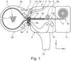
- Fig. 1 schematically shows an exemplary bundling tool.
- the bundling tool 1 has a central housing 1a with a handle unit 1b. Instead of the handle unit 1b, the central housing 1a may have a mechanical and/or electrical interface for coupling with a robot.
- the bundling tool 1 has an exchangeable jaw unit 2 for guiding an end section 3a of an endless strap 3 around a bundling good 4.
- the endless strap 3 has a toothing 3b, which in the present case is arranged on an outer side of the endless strap 3 facing away from the bundling good 4 during intended use.
- the endless strap 3 is fed from a reservoir unit 1c, in which it is held, for example, in the form of a roll.
- the reservoir unit 1c can be designed as a separate unit from the bundling tool 1.
- the jaw unit 2 has an upper jaw claw 2a and a lower jaw claw 2b which can be opened and closed.
- a lock feeding unit 5 provides a respective lock element 15 for the current bundling process from an external or internal reservoir of lock elements 15 not shown here.
- the bundling tool 1 also has a pushing and pulling unit 6, which is provided, in the present example, with a drive 6a engaging in the toothing 3b for pushing the end section 3a of the endless strap 3 by means of a motor along a path 7 through the provided lock element 15 as well as along the jaw unit 2, with the bundling good 4 gripped by the jaw unit 2 around the bundling good 4, and back into the provided lock element 15, as well as for the subsequent retraction of the end section 3a of the endless strap 3.
- a pushing and pulling unit 6 which is provided, in the present example, with a drive 6a engaging in the toothing 3b for pushing the end section 3a of the endless strap 3 by means of a motor along a path 7 through the provided lock element 15 as well as along the jaw unit 2, with the bundling good 4 gripped by the jaw unit 2 around the bundling good 4, and back into the provided lock element 15, as well as for the subsequent retraction of the end section 3a of the endless strap 3.
- the bundling tool 1 also has a sensor unit 8 for detecting the end section 3a pushed back into the lock element 15, in this case with a mechanical stop element 8a, against which one end 3a' of the end section 3a abuts during the pushing along the path 7 and thus triggers a sensor signal.
- a cutting unit 9 for separating the end section 3a arranged around the bundling good 4 from a remaining section 3c of the endless strap 3 remaining in the bundling tool 1 after the end section 3a has been pulled back and thus after the bundling good 4 has been tied is also part of the bundling tool 1.
- the separation takes place in this case by means of a blade element 9a, which is moved here in the positive y-direction in order to cut off and thus separate the remaining section 3c protruding in the positive x-direction over the lock element 15 (which at least in parts then forms the new end section to be guided around the bundling good 4 in a subsequent bundling process) after the retraction.
- the bundling tool 1 has a control unit 10 which is designed to preset, in a normal operating mode for a first path portion 7a ( Fig. 2 ) of the path 7 for the pushing and pulling unit 6 during pushing, a greater pushing speed of the end section 3a than for a second path portion 7b ( Fig. 2 ) following the first path portion 7a, the second path portion 7b comprising the part of the path 7 running back into the lock element 15.
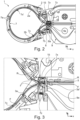
- the path 7 is shown in more detail.
- the second path portion 7b runs from a point 7y of the path 7 to an end point 7z of the path 7, to which the end section 3a is pushed back through the lock element 15.
- the first path portion 7a runs from a starting point 7x of the path 7 at the mouth of the lock element 15, through which the end section 3a is pushed at the beginning of the respective bundling process.
- the respective path portions 7a, 7b more precisely their lengths, which can be measured and/or specified in an equivalent-of-distance such as a number of teeth of the toothing 3b and/or a number of encoder or motor steps of the drive 6a or the associated motor, can be determined in a calibration operating mode of the control unit 10 for the respective jaw unit 2 used. In this way, the behavior of the pushing and pulling unit 6 in use can be determined partially or fully automatically for the respective size of the jaw unit 2, i.e. the length of the path 7 caused by the design.
- control unit 10 is then designed to specify a lower pushing speed of the end section 3a for the pushing and pulling unit 6 in the calibration operating mode for the first path portion 7a than in the normal operating mode and to determine the equivalent-of-distance, for example one of the above-mentioned equivalent-of-distances, for the first path portion 7a in the calibration operating mode.
- the pushing speed for the second path portion 7b can be preset in the normal operating mode for the first path portion 7a and also for the second path portion 7b for the pushing and pulling unit 6.
- the first path portion 7a and/or for the second path portion 7b can have a different pushing speed, for example a pushing speed that is even lower than that of the second path portion in the normal operating mode.
- the equivalent-of-distance can be determined with better accuracy at a lower pushing speed than at a higher pushing speed. In practice, it is necessary to weigh up between a desired higher speed of the bundling process and a desired higher accuracy when determining the equivalent-of-distance.
- the length of the second path portion 7b is to be preset by and/or for the control unit 10 to be as short as possible, whereby respective switching speeds between pushing the endless strap 3 in a forward direction F ( Fig. 3 ) and the subsequent retraction of the endless strap 3 in a reverse direction R ( Fig. 3 ) of the control unit 10 and/or the pushing and pulling unit 6 are a limiting factor.
- the first path portion 7a does not have to start at the starting point 7x either, it can also start at a further point 7x'.
- a higher pushing speed can be specified for an initial path portion between points 7x and 7x', for example the higher pushing speed of the normal operating mode.
- the length of the initial path portion can be, for example, the length of the first path portion 7a from starting point 7x to point 7y for a smallest jaw unit 2 used or available for the bundling tool 1 and/or a shorter length.
- the normal operation mode may also comprise or be a calibrating normal operation mode. This is explained by way of example with reference to Fig. 3 .
- the end 3a' of the endless strap 3 is at the start position 7x.
- the end 3a' and the end section 3a adjoining the end 3a' are first pushed by the pushing and pulling unit 6 in the forward direction F through the lock element 15 and along the path 7.
- the pushing speed is reduced when position 7y is reached in order to reduce the probability of faulty tying.
- the sensor signal is triggered and the push/pull unit now pulls the endless strap 3 back in the reverse direction R to bundle the material to be bound 4 as intended.
- a (particularly a relative) equivalent-of-time between the bundle process trigger signal and the sensor signal can be detected and compared with a stored (particularly relative) equivalent-of-time. Only if the two equivalents-of-time match is it possible to continue with the previous normal operating mode, i.e. the previous lengths for the first and/or second equivalent-of-distance 7a, 7b.
- the control unit 10 can automatically adjust the length of the first path portion 7a to the later or earlier triggering of the sensor signal, i.e., lengthen or shorten it accordingly, and then in turn adjust the stored equivalent-of-time to the new length of the first path portion 7a.
- the bundling tool 1 calibrates itself during the intended use and adjusts itself accordingly in an optimal way to jaw units 2 of different sizes.
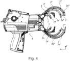
- Fig. 4 shows exemplary jaw units 2, 2', 2", 2′′′ of different sizes on an exemplary bundling tool 1.
- the jaw units 2, 2', 2", 2′′′ can be repeatedly exchanged without destruction, preferably without tools or with a limited number and/or complexity of tools.
- the respective paths 7, 7′′′ and thus in particular also the first path portions 7a are each of different length.
- the second path portions 7b can be of the same length, since the suitable length is determined by further properties of the respective bundling tool 1, such as, for example, a reaction speed of the control unit 10.
Landscapes
- Engineering & Computer Science (AREA)
- Mechanical Engineering (AREA)
- Basic Packing Technique (AREA)
Applications Claiming Priority (1)
| Application Number | Priority Date | Filing Date | Title |
|---|---|---|---|
| DE202023100955.7U DE202023100955U1 (de) | 2023-02-28 | 2023-02-28 | Verbessertes Bündelwerkzeug zum abfallfreien Bündeln eines Bindeguts |
Publications (1)
| Publication Number | Publication Date |
|---|---|
| EP4428045A1 true EP4428045A1 (fr) | 2024-09-11 |
Family
ID=90014467
Family Applications (1)
| Application Number | Title | Priority Date | Filing Date |
|---|---|---|---|
| EP24158647.8A Pending EP4428045A1 (fr) | 2023-02-28 | 2024-02-20 | Outil de liage pour le liage sans déchets d'un matériau de liaison |
Country Status (6)
| Country | Link |
|---|---|
| US (1) | US20240286781A1 (fr) |
| EP (1) | EP4428045A1 (fr) |
| JP (1) | JP7749726B2 (fr) |
| KR (1) | KR20240133642A (fr) |
| CN (1) | CN118560763A (fr) |
| DE (1) | DE202023100955U1 (fr) |
Citations (2)
| Publication number | Priority date | Publication date | Assignee | Title |
|---|---|---|---|---|
| US4610067A (en) * | 1984-07-10 | 1986-09-09 | Nifco Inc. | Binding tool |
| DE102018110184A1 (de) * | 2018-04-27 | 2019-10-31 | A. Raymond Et Cie Scs | Bindegerät und Verfahren zum automatisierten Bündeln von Kabelsträngen |
Family Cites Families (6)
| Publication number | Priority date | Publication date | Assignee | Title |
|---|---|---|---|---|
| JPH0740917A (ja) | 1993-07-21 | 1995-02-10 | Kioritz Corp | 梱包機 |
| JPH10250703A (ja) * | 1997-03-13 | 1998-09-22 | Toyota Kihan:Kk | 鉄筋結束機 |
| DE50108301D1 (de) | 2001-02-12 | 2006-01-12 | Hellermann Tyton Gmbh | Werkzeug zum Binden eines Gegenstandes, insbesondere eines Kabelbaums |
| DE102013222924A1 (de) | 2013-11-11 | 2015-05-28 | Hellermann Tyton Gmbh | Portables Kabelbindewerkzeug |
| JP6985928B2 (ja) | 2017-12-27 | 2021-12-22 | 株式会社マキタ | 結束機 |
| FR3079104B1 (fr) | 2018-03-20 | 2020-05-29 | Pellenc | Appareil pour la pose d'attaches filaires |
-
2023
- 2023-02-28 DE DE202023100955.7U patent/DE202023100955U1/de active Active
-
2024
- 2024-02-13 US US18/440,525 patent/US20240286781A1/en active Pending
- 2024-02-20 EP EP24158647.8A patent/EP4428045A1/fr active Pending
- 2024-02-27 JP JP2024027396A patent/JP7749726B2/ja active Active
- 2024-02-27 CN CN202410214643.XA patent/CN118560763A/zh active Pending
- 2024-02-27 KR KR1020240028006A patent/KR20240133642A/ko active Pending
Patent Citations (2)
| Publication number | Priority date | Publication date | Assignee | Title |
|---|---|---|---|---|
| US4610067A (en) * | 1984-07-10 | 1986-09-09 | Nifco Inc. | Binding tool |
| DE102018110184A1 (de) * | 2018-04-27 | 2019-10-31 | A. Raymond Et Cie Scs | Bindegerät und Verfahren zum automatisierten Bündeln von Kabelsträngen |
Also Published As
| Publication number | Publication date |
|---|---|
| CN118560763A (zh) | 2024-08-30 |
| JP7749726B2 (ja) | 2025-10-06 |
| DE202023100955U1 (de) | 2024-05-29 |
| US20240286781A1 (en) | 2024-08-29 |
| KR20240133642A (ko) | 2024-09-04 |
| JP2024122924A (ja) | 2024-09-09 |
Similar Documents
| Publication | Publication Date | Title |
|---|---|---|
| US9004114B2 (en) | Reinforcing bar binding machine | |
| EP1564146A1 (fr) | Compteur pour outill d'installation de serre-câbles | |
| EP1070808B1 (fr) | Machine à ligaturer les barres d'armatures | |
| JP5421281B2 (ja) | 電気モータによって駆動される携帯用リベット打ち装置を用いたリベット要素を設置する方法およびリベット打ち装置 | |
| EP4276024B1 (fr) | Dispositif automatique d'outillage de mise en faisceau, abt, pour la mise en faisceau d'un produit à mettre en faisceau avec un lien d'une seule pièce avec surveillance de qualité | |
| EP0822304B1 (fr) | Dispositif pour empêcher la rupture d'un fil torsadé dans un machine à ligaturer des fers d'armature | |
| US20130125710A1 (en) | Wire stripper | |
| US20160280405A1 (en) | Portable cable tie tool | |
| CN110155403A (zh) | 电动工具 | |
| EP1657022B1 (fr) | Dispositif d'identification de collision | |
| US6928787B2 (en) | Banding packing machine | |
| WO2009123837A1 (fr) | Outil d'attache métallique à tension retenue | |
| EP0822303B1 (fr) | Dispositif pour empêcher l'entrelacement du fil dans une machine à ligaturer les fers d'armature | |
| CN101910531A (zh) | 捆绑装置 | |
| EP1840030A1 (fr) | Machine à lier les tiges de renforcement | |
| US20240286781A1 (en) | Bundling Tool for Waste-Free Bundling of Binding Material | |
| CN110406720A (zh) | 捆扎装置和用于自动捆扎线缆的方法 | |
| TWI714842B (zh) | 捆束機 | |
| US20050050932A1 (en) | Cutting head for wire-processing machine | |
| CN207488791U (zh) | 一种并丝机的自动打结电气控制结构 | |
| EP0630701B1 (fr) | Méthode et dispositif d'alignement du bout de barres | |
| JPH0592103U (ja) | 結束機における結束用ワイヤの案内装置 | |
| US20250041931A1 (en) | Binding tool | |
| US20230226593A1 (en) | Binding system, method for controlling binding device, and computer readable storage medium storing program | |
| JP2012204102A (ja) | 端子圧着装置 |
Legal Events
| Date | Code | Title | Description |
|---|---|---|---|
| PUAI | Public reference made under article 153(3) epc to a published international application that has entered the european phase |
Free format text: ORIGINAL CODE: 0009012 |
|
| STAA | Information on the status of an ep patent application or granted ep patent |
Free format text: STATUS: THE APPLICATION HAS BEEN PUBLISHED |
|
| AK | Designated contracting states |
Kind code of ref document: A1 Designated state(s): AL AT BE BG CH CY CZ DE DK EE ES FI FR GB GR HR HU IE IS IT LI LT LU LV MC ME MK MT NL NO PL PT RO RS SE SI SK SM TR |
|
| STAA | Information on the status of an ep patent application or granted ep patent |
Free format text: STATUS: REQUEST FOR EXAMINATION WAS MADE |
|
| 17P | Request for examination filed |
Effective date: 20241104 |
|
| RBV | Designated contracting states (corrected) |
Designated state(s): AL AT BE BG CH CY CZ DE DK EE ES FI FR GB GR HR HU IE IS IT LI LT LU LV MC ME MK MT NL NO PL PT RO RS SE SI SK SM TR |
|
| RAP3 | Party data changed (applicant data changed or rights of an application transferred) |
Owner name: HELLERMANNTYTON GMBH & CO. KG |