EP4428070A1 - Sortiersystem - Google Patents
Sortiersystem Download PDFInfo
- Publication number
- EP4428070A1 EP4428070A1 EP23160173.3A EP23160173A EP4428070A1 EP 4428070 A1 EP4428070 A1 EP 4428070A1 EP 23160173 A EP23160173 A EP 23160173A EP 4428070 A1 EP4428070 A1 EP 4428070A1
- Authority
- EP
- European Patent Office
- Prior art keywords
- input
- output
- conveying direction
- sorting system
- cross
- Prior art date
- Legal status (The legal status is an assumption and is not a legal conclusion. Google has not performed a legal analysis and makes no representation as to the accuracy of the status listed.)
- Pending
Links
- 239000000969 carrier Substances 0.000 claims abstract description 37
- 238000007599 discharging Methods 0.000 claims abstract description 7
- 230000004888 barrier function Effects 0.000 claims description 13
- 238000006073 displacement reaction Methods 0.000 description 4
- 230000003068 static effect Effects 0.000 description 3
- 230000032258 transport Effects 0.000 description 1
Images


Classifications
-
- B—PERFORMING OPERATIONS; TRANSPORTING
- B65—CONVEYING; PACKING; STORING; HANDLING THIN OR FILAMENTARY MATERIAL
- B65G—TRANSPORT OR STORAGE DEVICES, e.g. CONVEYORS FOR LOADING OR TIPPING, SHOP CONVEYOR SYSTEMS OR PNEUMATIC TUBE CONVEYORS
- B65G47/00—Article or material-handling devices associated with conveyors; Methods employing such devices
- B65G47/74—Feeding, transfer, or discharging devices of particular kinds or types
- B65G47/94—Devices for flexing or tilting travelling structures; Throw-off carriages
- B65G47/96—Devices for tilting links or platform
-
- B—PERFORMING OPERATIONS; TRANSPORTING
- B07—SEPARATING SOLIDS FROM SOLIDS; SORTING
- B07C—POSTAL SORTING; SORTING INDIVIDUAL ARTICLES, OR BULK MATERIAL FIT TO BE SORTED PIECE-MEAL, e.g. BY PICKING
- B07C5/00—Sorting according to a characteristic or feature of the articles or material being sorted, e.g. by control effected by devices which detect or measure such characteristic or feature; Sorting by manually actuated devices, e.g. switches
- B07C5/36—Sorting apparatus characterised by the means used for distribution
-
- B—PERFORMING OPERATIONS; TRANSPORTING
- B65—CONVEYING; PACKING; STORING; HANDLING THIN OR FILAMENTARY MATERIAL
- B65G—TRANSPORT OR STORAGE DEVICES, e.g. CONVEYORS FOR LOADING OR TIPPING, SHOP CONVEYOR SYSTEMS OR PNEUMATIC TUBE CONVEYORS
- B65G47/00—Article or material-handling devices associated with conveyors; Methods employing such devices
- B65G47/74—Feeding, transfer, or discharging devices of particular kinds or types
- B65G47/84—Star-shaped wheels or devices having endless travelling belts or chains, the wheels or devices being equipped with article-engaging elements
- B65G47/841—Devices having endless travelling belts or chains equipped with article-engaging elements
- B65G47/844—Devices having endless travelling belts or chains equipped with article-engaging elements the article-engaging elements being pushers transversally movable on the supporting surface, e.g. pusher-shoes
Definitions
- the present invention relates to a sorting system, comprising a frame which supports an input conveyor including an input supporting surface for supporting articles, which input conveyor is drivable with respect to the frame in an input conveying direction and an output conveyor having a plurality of discrete carriers including respective output supporting surfaces for supporting articles, which carriers are drivable with respect to the frame in an output conveying direction and are located behind each other in the output conveying direction, a transfer region where the input supporting surface and a part of the carriers extend parallel to each other as seen from above and move synchronously in the same direction under operating conditions, wherein the input conveyor is provided with input displacing members which are located behind each other in the input conveying direction and move synchronously with the input supporting surface in the input conveying direction (X) under operating conditions, wherein the input displacing members are drivable with respect to the frame in transverse direction of the input conveying direction, wherein at the transfer region the input displacing members and the output supporting surfaces are aligned with each other.
- Such a sorting system is known in the prior art.
- an article which is supported by the input supporting surface is transported in the input conveying direction and simultaneously moved by one of the input displacing members across the input supporting surface towards a carrier that travels synchronously with that input displacing member at the transfer region.
- This is possible due to the alignment of the input displacing members and the output supporting surfaces at the transfer region.
- the input supporting surface and the output supporting surface of each of the carriers form a common supporting surface which have fixed positions with respect to each other at the transfer region.
- the output supporting surfaces of the respective carriers of the known sorting system can be selectively tilted at different discharge locations so as to drop articles to be sorted for different destinations.
- the present invention aims to provide an improved sorting system.
- the carriers are provided with respective output displacing members for discharging articles from the output supporting surfaces in transverse direction of the output conveying direction.
- An advantage of the sorting system according to the invention is that it provides the opportunity to select one of the lateral sides of the output conveyor for discharging articles, which provides flexibility for locating the sorting system in a certain space. Besides, it provides the opportunity to sort and discharge articles at opposite sides of the output conveyor, hence providing a relatively high sorting capacity. It is noted that the articles can be supplied to the input conveyor synchronously with the conveying speed of the input conveyor and the carriers at the transfer region, for example by means of a supply conveyor, such that at the transfer region each article is located on the input supporting surface in alignment with one of the carriers.
- the output supporting surfaces of the carriers are upper surfaces of respective cross-belts which are mounted to carrier frames of the respective carriers, wherein each of the cross-belts is drivable with respect to the corresponding carrier frame in transverse direction of the output conveying direction, thus forming the output displacing member, such that at the transfer region the input displacing members and the upper surfaces of the cross-belts move in the same direction under operating conditions, since in this embodiment the cross-belts assist the input displacing members to transfer the articles to the output conveyor.
- each of the cross-belts can pull an article which is displaced by the cooperating input displacing member on its upper surface.
- each of the cross-belts is drivable with respect to the corresponding carrier frame such that at the transfer region the input displacing members and the upper surfaces of the cross-belts move synchronously under operating conditions. This minimizes friction between articles and the cross-belts during displacement from the input conveyor to the output conveyor.
- the input displacing members may comprise respective input pushing elements which are displaceable with respect to the input supporting surface.
- the input supporting surface may be displaceable in the input conveying direction only and the input pushing elements can slide articles across the input supporting surface by pushing them.
- the input conveyor may comprises an endless slat belt having an upper section and a lower section which extend above each other in a vertical plane, wherein the input supporting surface is formed by an upper surface of the upper section of the slat belt.
- the slats may be elongate and extend in transverse direction of the input conveying direction.
- the input pushing elements may be movable along the slats. In a well-known manner, displacement of the input pushing elements may be forced by an input guide which is fixed to the frame and extends below the slats, whereas each of the pushing elements may contact the input guide through a link between two neighbouring slats during passing the input guide.
- the upper surfaces of the respective cross-belts may be free from obstacles.
- a cross-belt conveyor may be known as a cross-belt sorter.
- the cross-belts may be endless cross-belts, for example.
- each of the cross-belts is provided with at least two barriers, which are located at a distance from each other in transverse direction of the output conveying direction such that upon leaving the transfer region under operating conditions the barriers project upwardly from the cross-belts and the output upper surface of each cross-belt extends between the barriers. This prevents an article from being prematurely discharged from the carrier, for example in a bend of the path that is followed by the carriers.
- a cross-belt conveyor as such may be known as a cross-tray sorter.
- the output supporting surfaces are upper surfaces of respective trays, wherein the output displacing members comprise respective output pushing elements which are movable with respect to the trays in transverse direction of the output conveying direction.
- Such an output conveyor as such may be known as a push-tray sorter.
- the output displacing members may be drivable with respect to the frame in opposite directions. This is advantageous since articles can be sorted and discharged at opposite sides of the output conveyor, hence providing a relatively high sorting capacity.
- the transfer region may comprise a linear path.
- the input supporting surface and the output supporting surfaces may be flush in order to create a smooth transfer of articles.
- the input conveyor may be controllable such that under operating conditions an input displacing member remains in place at the transfer region. This means that the input displacing members are selectively drivable in transverse direction of the input conveying direction.
- An advantage of this embodiment is that an article which is received by the input conveyor will not be transferred to the output conveyor. This situation may be desired when a carrier which arrives at the transfer region has not discharged an article yet or when it appears that a wrong article, which should not be sorted, is supplied to the input conveyor.
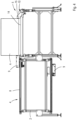
- Fig. 1 shows an embodiment of a sorting system 1 according to the invention as seen from above.
- the sorting system 1 comprises a frame 2 which supports a supply conveyor 3, an input conveyor 4 and an output conveyor 5. Under operating conditions the input conveyor 4 receives articles A to be sorted from the supply conveyor 3. At a transfer region 6 the articles A are transferred from the input conveyor 4 to the output conveyor 5, which in turn transports the articles A to a discharge station 7 where the articles A are selectively discharged from the output conveyor 5 to different receivers (not shown) at lateral sides of the output conveyor 5, corresponding to different destinations.
- the input conveyor 4 comprises a drivable endless slat belt 8 including interconnected elongate slats, which are movable with respect to each other. Under operating conditions the slat belt 8 follows a closed loop path in a vertical plane and forms an upper section and a lower section between reversing rollers. A common upper surface of the upper section of the slat belt 8 forms an input supporting surface for supporting and transporting the articles A. The input supporting surface moves in an input conveying direction X under operating conditions, as indicated in Fig. 1 .
- the input conveyor 4 comprises input displacing members in the form of input pushing elements 9 which travel with the slat belt 8 under operating conditions.
- the input pushing elements 9 are movable with respect to the slats in longitudinal direction thereof, i.e. in transverse direction of the input conveying direction X. This means that an article A on the slat belt 8 can be slid across the upper surface of the slat belt 8 by one of the input pushing element 9.
- the output conveyor 5 is provided with a plurality of interconnected carriers 10 which are supported by the frame 2 and drivable with respect to the frame 2 in an output conveying direction Y.
- the carriers 10 are located behind each other in the output conveying direction Y and are mounted to each other such that that they can follow a non-linear path. In the embodiment as shown in Fig. 1 the carriers 10 follow a closed loop path within a horizontal plane, but numerous alternative path shapes are conceivable.
- Each of the carriers 10 has an output displacing member in the form of a cross-belt 11 which is drivable with respect to a carrier frame of the carrier 10 in transverse direction of the output conveying direction Y, see Fig. 2 .
- the cross-belts 11 are drivable in opposite directions in order to discharge the articles A from the carriers 10 at both sides of the output conveyor 5 at the discharge station 7 as illustrated by arrows in Fig. 1 .
- the upper section of the slat belt 8 and a part of the carriers 10 extend parallel to each other as seen from above.
- the upper section of the slat belt 8 and the cooperating carriers 10 move synchronously in the same direction under operating conditions. This means that their conveying speeds as well as the input conveying direction X and the output conveying direction Y are the same.
- the cross-belts 11 and the respective input pushing elements 9 are aligned with each other such that each input pushing element 9 can displace an article A from the slat belt 8 towards the cross-belt 11 of a cooperating carrier 10.
- pairs of input pushing elements 9 and carriers 10 move synchronously in the same direction whereas at each pair an article A can be displaced by the input pushing element 7 from the slat belt 8 to the cooperating cross-belt 11.
- the articles A are supplied by the supply conveyor 3 to the slat belt 8 synchronously with displacement of the slat belt 8 and the carriers 10 such that at the transfer region 6 each article A is located on the slat belt 8 in alignment with one of the carriers 10.
- the input conveyor 4 may be provided with an input guide (not shown) which is fixed to the frame 2 and extends below the upper section of the slat belt 8 whereas the input pushing elements 9 are provided with contact elements which pass between adjacent slats of the slat belt 8 and can engage the input guide at the transfer region 6 such that the input guide defines displacements of the input pushing elements 9 along the slats upon moving the upper section of the slat belt 8 in the input conveying direction X.
- the input pushing elements 9 may be returned to their initial positions by a return guide at the input conveyor 4 when the contact elements 9 of the pushing elements 5 engage the return guide.
- Such a control system for displacing the input pushing elements 9 as such is known by the skilled person.
- the input conveyor 4 may be controllable such that under certain circumstances one of the input pushing elements 9 is not displaced towards a cooperating carrier 10 after receiving an article A from the supply conveyor 3. This means that the article A is only transported in the input conveying direction X by the slat belt 8 and will not be transported by the output conveyor 5. Such a situation may happen when a carrier 10 which arrives at the transfer region 6 is still not empty or when it is detected that an article A which is supplied by the supply conveyor 3 should not be transferred to the output conveyor 5.
- the output conveyor 5 is provided with output guides 12 which are fixed to the frame 2 and extend below the carriers 10 whereas the cross-belts 11 are provided with contact elements which can selectively engage the output guides 12 for discharging an article A from the carrier 10 in a well-known manner.
- the output guides 12 are adapted such that they force the cross-belts 11 to move in the same direction as the input pushing elements 9 during passing the transfer region 6. This means that the articles A are pulled onto the carriers 10 by the cross-belts 11, preferably synchronously with the input pushing elements 9. This minimizes friction between the articles A and the cross-belts 11 on which the articles A are received.
- Fig. 2 shows that the level of the upper surface of the cross-belt 11 is slightly lower than the level of the common upper surface of the slat belt 8 at the transfer region 6. It is also possible that the common upper surface of the slat belt 8 and upper surfaces of the cross-belts 11 are flush at the transfer region 6.
- Fig. 3 shows an alternative embodiment, in which the output conveyor 5 is also provided with cross-belts 11, but each of the cross-belts 11 is provided with two barriers 13.
- the barriers 13 are located at a distance from each other in transverse direction of the output conveying direction Y, as measured along the cross-belt 11.
- the cross-belts 11 may be adapted and operated such that under operating conditions, when the carriers 10 leave the transfer region 6, both barriers 13 of each cross-belt 11 are directed upwardly such that the output supporting surface of the carrier 10 is formed between the barriers 13, whereas when the carriers 10 arrive at the transfer region 6 one of the barriers 13 is directed downwardly such that an article A which is moving to the output conveyor 5 is not hindered by one of the barriers 13.
- Fig. 3 shows a situation in which the cross-belt 11 is still moving to the right just before the left one of the barriers 13 also projects upwardly from the cross-belt 11.
- Fig. 4 shows another alternative embodiment, in which the carriers 10 of the output conveyor 5 have respective static trays 14 for receiving articles A and respective output displacing members in the form of output pushing elements 15 which are displaceable above the tray 14.
- the output pushing elements 15 may comprise respective elongate beams for pushing against articles A which beams extend in the output conveying direction Y in a well-known manner.
- a lower side of each of the output pushing elements 15 may be provided with a contact element for engaging the output guides 12, similar to the first embodiment as described hereinbefore.
- the output pushing elements 15 will be positioned at a distance from the input conveyor 4 in order to avoid hindering of an article A which is displaced from the input conveyor 4 to the carrier 10.
- the input conveyor may be a different type, such as a shoe sorter, or it may comprise discrete carriers including respective pushing elements.
Landscapes
- Engineering & Computer Science (AREA)
- Mechanical Engineering (AREA)
- Branching, Merging, And Special Transfer Between Conveyors (AREA)
- Discharge Of Articles From Conveyors (AREA)
Priority Applications (2)
| Application Number | Priority Date | Filing Date | Title |
|---|---|---|---|
| EP23160173.3A EP4428070A1 (de) | 2023-03-06 | 2023-03-06 | Sortiersystem |
| PCT/EP2024/055323 WO2024184210A1 (en) | 2023-03-06 | 2024-03-01 | A sorting system |
Applications Claiming Priority (1)
| Application Number | Priority Date | Filing Date | Title |
|---|---|---|---|
| EP23160173.3A EP4428070A1 (de) | 2023-03-06 | 2023-03-06 | Sortiersystem |
Publications (1)
| Publication Number | Publication Date |
|---|---|
| EP4428070A1 true EP4428070A1 (de) | 2024-09-11 |
Family
ID=85505430
Family Applications (1)
| Application Number | Title | Priority Date | Filing Date |
|---|---|---|---|
| EP23160173.3A Pending EP4428070A1 (de) | 2023-03-06 | 2023-03-06 | Sortiersystem |
Country Status (2)
| Country | Link |
|---|---|
| EP (1) | EP4428070A1 (de) |
| WO (1) | WO2024184210A1 (de) |
Citations (5)
| Publication number | Priority date | Publication date | Assignee | Title |
|---|---|---|---|---|
| JP2002068467A (ja) * | 2000-08-25 | 2002-03-08 | Okamura Corp | 物品の移載装置 |
| CN107088525A (zh) * | 2017-06-27 | 2017-08-25 | 深圳市步科电气有限公司 | 物流分拣系统及方法 |
| US20210009364A1 (en) * | 2019-01-24 | 2021-01-14 | Solystic | A parcel or packet sorting/handling system comprising a platform sorting conveyor loaded by a slat conveyor having pusher shoes |
| US20210162465A1 (en) * | 2019-11-28 | 2021-06-03 | Solystic | Installation for sorting articles such as parcels or packets with a system for monitoring the positioning of the articles by outline detection |
| EP4001190A1 (de) * | 2020-11-18 | 2022-05-25 | Eurosort B.V. | Sortiersystem zum sortieren von artikeln und verfahren zum betreiben des sortiersystems |
-
2023
- 2023-03-06 EP EP23160173.3A patent/EP4428070A1/de active Pending
-
2024
- 2024-03-01 WO PCT/EP2024/055323 patent/WO2024184210A1/en not_active Ceased
Patent Citations (5)
| Publication number | Priority date | Publication date | Assignee | Title |
|---|---|---|---|---|
| JP2002068467A (ja) * | 2000-08-25 | 2002-03-08 | Okamura Corp | 物品の移載装置 |
| CN107088525A (zh) * | 2017-06-27 | 2017-08-25 | 深圳市步科电气有限公司 | 物流分拣系统及方法 |
| US20210009364A1 (en) * | 2019-01-24 | 2021-01-14 | Solystic | A parcel or packet sorting/handling system comprising a platform sorting conveyor loaded by a slat conveyor having pusher shoes |
| US20210162465A1 (en) * | 2019-11-28 | 2021-06-03 | Solystic | Installation for sorting articles such as parcels or packets with a system for monitoring the positioning of the articles by outline detection |
| EP4001190A1 (de) * | 2020-11-18 | 2022-05-25 | Eurosort B.V. | Sortiersystem zum sortieren von artikeln und verfahren zum betreiben des sortiersystems |
Also Published As
| Publication number | Publication date |
|---|---|
| WO2024184210A1 (en) | 2024-09-12 |
Similar Documents
| Publication | Publication Date | Title |
|---|---|---|
| US4465177A (en) | Elevator for a conveying system | |
| EP1220719B1 (de) | Querbandsortiersystem | |
| EP3322963B1 (de) | Ablenkende kontrollwaage | |
| DK0480436T3 (da) | Indretning til fordeling og samling af produkter, som skal transporteres | |
| WO2007133672A2 (en) | Sortation conveyor apparatus and methods | |
| EP1203735B1 (de) | Förderer mit deformierbarem Förderband | |
| CN111448152B (zh) | 用于在两个传送装置之间移交传送物的方法和装置以及传送系统 | |
| US5450941A (en) | Apparatus for separating, conveying and grouping flat items | |
| EP3820793B1 (de) | Umlenkvorrichtung für förderbandplattform | |
| US3648820A (en) | Apparatus for feeding chocolate bars and the like to a packing machine | |
| US3735853A (en) | System for distributing pieces of load such as baggage, parcels etc. | |
| US12110191B2 (en) | Cross-belt sorter | |
| US3193080A (en) | Multiple station feeding means | |
| WO2024184210A1 (en) | A sorting system | |
| EP1533257A1 (de) | Vorrichtung zur Verbindung einer Verpackungsmaschine, insbesondere einer Blisterherstellungsmaschine, mit einem Zuführförderer für eine Einschachtelmaschine | |
| US8678174B2 (en) | Method and device for buffering products | |
| FI3914546T3 (en) | Parcel or package sorting/handling system comprising a tray sorting conveyor loaded by a slat conveyor with pusher shoes | |
| EP3798161B1 (de) | Vorrichtung zum transport und gesteuerte produktabgabe | |
| EP3795502B1 (de) | Pufferförderer | |
| EP3620413A1 (de) | Vorrichtung, system und verfahren zum sortieren von produkten | |
| US3451525A (en) | Sorting conveyor | |
| US3325005A (en) | Tableware sorter | |
| JPH08282830A (ja) | 仕分装置 | |
| EP0115916B1 (de) | Sortiermaschine | |
| JPH01162608A (ja) | ダンプトレー仕分け方法および装置 |
Legal Events
| Date | Code | Title | Description |
|---|---|---|---|
| PUAI | Public reference made under article 153(3) epc to a published international application that has entered the european phase |
Free format text: ORIGINAL CODE: 0009012 |
|
| STAA | Information on the status of an ep patent application or granted ep patent |
Free format text: STATUS: THE APPLICATION HAS BEEN PUBLISHED |
|
| AK | Designated contracting states |
Kind code of ref document: A1 Designated state(s): AL AT BE BG CH CY CZ DE DK EE ES FI FR GB GR HR HU IE IS IT LI LT LU LV MC ME MK MT NL NO PL PT RO RS SE SI SK SM TR |
|
| STAA | Information on the status of an ep patent application or granted ep patent |
Free format text: STATUS: REQUEST FOR EXAMINATION WAS MADE |
|
| 17P | Request for examination filed |
Effective date: 20250227 |