EP4428096A1 - Procédé de production d'hydrogène avec reformage de méthane à la vapeur chauffé électriquement - Google Patents
Procédé de production d'hydrogène avec reformage de méthane à la vapeur chauffé électriquement Download PDFInfo
- Publication number
- EP4428096A1 EP4428096A1 EP23160906.6A EP23160906A EP4428096A1 EP 4428096 A1 EP4428096 A1 EP 4428096A1 EP 23160906 A EP23160906 A EP 23160906A EP 4428096 A1 EP4428096 A1 EP 4428096A1
- Authority
- EP
- European Patent Office
- Prior art keywords
- stream
- hydrogen
- steam
- gas
- heat
- Prior art date
- Legal status (The legal status is an assumption and is not a legal conclusion. Google has not performed a legal analysis and makes no representation as to the accuracy of the status listed.)
- Pending
Links
Images


Classifications
-
- C—CHEMISTRY; METALLURGY
- C01—INORGANIC CHEMISTRY
- C01B—NON-METALLIC ELEMENTS; COMPOUNDS THEREOF; METALLOIDS OR COMPOUNDS THEREOF NOT COVERED BY SUBCLASS C01C
- C01B3/00—Hydrogen; Gaseous mixtures containing hydrogen; Separation of hydrogen from mixtures containing it; Purification of hydrogen; Reversible storage of hydrogen
- C01B3/02—Production of hydrogen; Production of gaseous mixtures containing hydrogen
- C01B3/32—Production of hydrogen; Production of gaseous mixtures containing hydrogen by reaction of gaseous or liquid organic compounds with gasifying agents, e.g. water, carbon dioxide or air
- C01B3/34—Production of hydrogen; Production of gaseous mixtures containing hydrogen by reaction of gaseous or liquid organic compounds with gasifying agents, e.g. water, carbon dioxide or air by reaction of hydrocarbons with gasifying agents
- C01B3/48—Production of hydrogen; Production of gaseous mixtures containing hydrogen by reaction of gaseous or liquid organic compounds with gasifying agents, e.g. water, carbon dioxide or air by reaction of hydrocarbons with gasifying agents followed by reaction of water vapour with carbon monoxide
-
- C—CHEMISTRY; METALLURGY
- C01—INORGANIC CHEMISTRY
- C01B—NON-METALLIC ELEMENTS; COMPOUNDS THEREOF; METALLOIDS OR COMPOUNDS THEREOF NOT COVERED BY SUBCLASS C01C
- C01B3/00—Hydrogen; Gaseous mixtures containing hydrogen; Separation of hydrogen from mixtures containing it; Purification of hydrogen; Reversible storage of hydrogen
- C01B3/02—Production of hydrogen; Production of gaseous mixtures containing hydrogen
- C01B3/32—Production of hydrogen; Production of gaseous mixtures containing hydrogen by reaction of gaseous or liquid organic compounds with gasifying agents, e.g. water, carbon dioxide or air
- C01B3/34—Production of hydrogen; Production of gaseous mixtures containing hydrogen by reaction of gaseous or liquid organic compounds with gasifying agents, e.g. water, carbon dioxide or air by reaction of hydrocarbons with gasifying agents
- C01B3/38—Production of hydrogen; Production of gaseous mixtures containing hydrogen by reaction of gaseous or liquid organic compounds with gasifying agents, e.g. water, carbon dioxide or air by reaction of hydrocarbons with gasifying agents using catalysts
- C01B3/384—Production of hydrogen; Production of gaseous mixtures containing hydrogen by reaction of gaseous or liquid organic compounds with gasifying agents, e.g. water, carbon dioxide or air by reaction of hydrocarbons with gasifying agents using catalysts with external heating of the catalyst
-
- C—CHEMISTRY; METALLURGY
- C01—INORGANIC CHEMISTRY
- C01B—NON-METALLIC ELEMENTS; COMPOUNDS THEREOF; METALLOIDS OR COMPOUNDS THEREOF NOT COVERED BY SUBCLASS C01C
- C01B3/00—Hydrogen; Gaseous mixtures containing hydrogen; Separation of hydrogen from mixtures containing it; Purification of hydrogen; Reversible storage of hydrogen
- C01B3/50—Separation of hydrogen or hydrogen-containing gases from gaseous mixtures, e.g. purification
-
- C—CHEMISTRY; METALLURGY
- C01—INORGANIC CHEMISTRY
- C01B—NON-METALLIC ELEMENTS; COMPOUNDS THEREOF; METALLOIDS OR COMPOUNDS THEREOF NOT COVERED BY SUBCLASS C01C
- C01B2203/00—Integrated processes for the production of hydrogen or synthesis gas
- C01B2203/02—Processes for making hydrogen or synthesis gas
- C01B2203/0205—Processes for making hydrogen or synthesis gas containing a reforming step
- C01B2203/0211—Processes for making hydrogen or synthesis gas containing a reforming step containing a non-catalytic reforming step
- C01B2203/0216—Processes for making hydrogen or synthesis gas containing a reforming step containing a non-catalytic reforming step containing a non-catalytic steam reforming step
-
- C—CHEMISTRY; METALLURGY
- C01—INORGANIC CHEMISTRY
- C01B—NON-METALLIC ELEMENTS; COMPOUNDS THEREOF; METALLOIDS OR COMPOUNDS THEREOF NOT COVERED BY SUBCLASS C01C
- C01B2203/00—Integrated processes for the production of hydrogen or synthesis gas
- C01B2203/02—Processes for making hydrogen or synthesis gas
- C01B2203/0205—Processes for making hydrogen or synthesis gas containing a reforming step
- C01B2203/0227—Processes for making hydrogen or synthesis gas containing a reforming step containing a catalytic reforming step
- C01B2203/0233—Processes for making hydrogen or synthesis gas containing a reforming step containing a catalytic reforming step the reforming step being a steam reforming step
-
- C—CHEMISTRY; METALLURGY
- C01—INORGANIC CHEMISTRY
- C01B—NON-METALLIC ELEMENTS; COMPOUNDS THEREOF; METALLOIDS OR COMPOUNDS THEREOF NOT COVERED BY SUBCLASS C01C
- C01B2203/00—Integrated processes for the production of hydrogen or synthesis gas
- C01B2203/02—Processes for making hydrogen or synthesis gas
- C01B2203/0283—Processes for making hydrogen or synthesis gas containing a CO-shift step, i.e. a water gas shift step
-
- C—CHEMISTRY; METALLURGY
- C01—INORGANIC CHEMISTRY
- C01B—NON-METALLIC ELEMENTS; COMPOUNDS THEREOF; METALLOIDS OR COMPOUNDS THEREOF NOT COVERED BY SUBCLASS C01C
- C01B2203/00—Integrated processes for the production of hydrogen or synthesis gas
- C01B2203/04—Integrated processes for the production of hydrogen or synthesis gas containing a purification step for the hydrogen or the synthesis gas
- C01B2203/0405—Purification by membrane separation
- C01B2203/041—In-situ membrane purification during hydrogen production
-
- C—CHEMISTRY; METALLURGY
- C01—INORGANIC CHEMISTRY
- C01B—NON-METALLIC ELEMENTS; COMPOUNDS THEREOF; METALLOIDS OR COMPOUNDS THEREOF NOT COVERED BY SUBCLASS C01C
- C01B2203/00—Integrated processes for the production of hydrogen or synthesis gas
- C01B2203/04—Integrated processes for the production of hydrogen or synthesis gas containing a purification step for the hydrogen or the synthesis gas
- C01B2203/0415—Purification by absorption in liquids
-
- C—CHEMISTRY; METALLURGY
- C01—INORGANIC CHEMISTRY
- C01B—NON-METALLIC ELEMENTS; COMPOUNDS THEREOF; METALLOIDS OR COMPOUNDS THEREOF NOT COVERED BY SUBCLASS C01C
- C01B2203/00—Integrated processes for the production of hydrogen or synthesis gas
- C01B2203/04—Integrated processes for the production of hydrogen or synthesis gas containing a purification step for the hydrogen or the synthesis gas
- C01B2203/042—Purification by adsorption on solids
- C01B2203/043—Regenerative adsorption process in two or more beds, one for adsorption, the other for regeneration
-
- C—CHEMISTRY; METALLURGY
- C01—INORGANIC CHEMISTRY
- C01B—NON-METALLIC ELEMENTS; COMPOUNDS THEREOF; METALLOIDS OR COMPOUNDS THEREOF NOT COVERED BY SUBCLASS C01C
- C01B2203/00—Integrated processes for the production of hydrogen or synthesis gas
- C01B2203/04—Integrated processes for the production of hydrogen or synthesis gas containing a purification step for the hydrogen or the synthesis gas
- C01B2203/0465—Composition of the impurity
- C01B2203/047—Composition of the impurity the impurity being carbon monoxide
-
- C—CHEMISTRY; METALLURGY
- C01—INORGANIC CHEMISTRY
- C01B—NON-METALLIC ELEMENTS; COMPOUNDS THEREOF; METALLOIDS OR COMPOUNDS THEREOF NOT COVERED BY SUBCLASS C01C
- C01B2203/00—Integrated processes for the production of hydrogen or synthesis gas
- C01B2203/04—Integrated processes for the production of hydrogen or synthesis gas containing a purification step for the hydrogen or the synthesis gas
- C01B2203/0465—Composition of the impurity
- C01B2203/0475—Composition of the impurity the impurity being carbon dioxide
-
- C—CHEMISTRY; METALLURGY
- C01—INORGANIC CHEMISTRY
- C01B—NON-METALLIC ELEMENTS; COMPOUNDS THEREOF; METALLOIDS OR COMPOUNDS THEREOF NOT COVERED BY SUBCLASS C01C
- C01B2203/00—Integrated processes for the production of hydrogen or synthesis gas
- C01B2203/04—Integrated processes for the production of hydrogen or synthesis gas containing a purification step for the hydrogen or the synthesis gas
- C01B2203/0465—Composition of the impurity
- C01B2203/0495—Composition of the impurity the impurity being water
-
- C—CHEMISTRY; METALLURGY
- C01—INORGANIC CHEMISTRY
- C01B—NON-METALLIC ELEMENTS; COMPOUNDS THEREOF; METALLOIDS OR COMPOUNDS THEREOF NOT COVERED BY SUBCLASS C01C
- C01B2203/00—Integrated processes for the production of hydrogen or synthesis gas
- C01B2203/08—Methods of heating or cooling
- C01B2203/0805—Methods of heating the process for making hydrogen or synthesis gas
- C01B2203/0811—Methods of heating the process for making hydrogen or synthesis gas by combustion of fuel
- C01B2203/0827—Methods of heating the process for making hydrogen or synthesis gas by combustion of fuel at least part of the fuel being a recycle stream
-
- C—CHEMISTRY; METALLURGY
- C01—INORGANIC CHEMISTRY
- C01B—NON-METALLIC ELEMENTS; COMPOUNDS THEREOF; METALLOIDS OR COMPOUNDS THEREOF NOT COVERED BY SUBCLASS C01C
- C01B2203/00—Integrated processes for the production of hydrogen or synthesis gas
- C01B2203/08—Methods of heating or cooling
- C01B2203/0805—Methods of heating the process for making hydrogen or synthesis gas
- C01B2203/085—Methods of heating the process for making hydrogen or synthesis gas by electric heating
-
- C—CHEMISTRY; METALLURGY
- C01—INORGANIC CHEMISTRY
- C01B—NON-METALLIC ELEMENTS; COMPOUNDS THEREOF; METALLOIDS OR COMPOUNDS THEREOF NOT COVERED BY SUBCLASS C01C
- C01B2203/00—Integrated processes for the production of hydrogen or synthesis gas
- C01B2203/08—Methods of heating or cooling
- C01B2203/0805—Methods of heating the process for making hydrogen or synthesis gas
- C01B2203/0866—Methods of heating the process for making hydrogen or synthesis gas by combination of different heating methods
-
- C—CHEMISTRY; METALLURGY
- C01—INORGANIC CHEMISTRY
- C01B—NON-METALLIC ELEMENTS; COMPOUNDS THEREOF; METALLOIDS OR COMPOUNDS THEREOF NOT COVERED BY SUBCLASS C01C
- C01B2203/00—Integrated processes for the production of hydrogen or synthesis gas
- C01B2203/12—Feeding the process for making hydrogen or synthesis gas
- C01B2203/1205—Composition of the feed
- C01B2203/1211—Organic compounds or organic mixtures used in the process for making hydrogen or synthesis gas
- C01B2203/1235—Hydrocarbons
- C01B2203/1241—Natural gas or methane
-
- C—CHEMISTRY; METALLURGY
- C01—INORGANIC CHEMISTRY
- C01B—NON-METALLIC ELEMENTS; COMPOUNDS THEREOF; METALLOIDS OR COMPOUNDS THEREOF NOT COVERED BY SUBCLASS C01C
- C01B2203/00—Integrated processes for the production of hydrogen or synthesis gas
- C01B2203/12—Feeding the process for making hydrogen or synthesis gas
- C01B2203/1258—Pre-treatment of the feed
- C01B2203/1264—Catalytic pre-treatment of the feed
- C01B2203/127—Catalytic desulfurisation
-
- C—CHEMISTRY; METALLURGY
- C01—INORGANIC CHEMISTRY
- C01B—NON-METALLIC ELEMENTS; COMPOUNDS THEREOF; METALLOIDS OR COMPOUNDS THEREOF NOT COVERED BY SUBCLASS C01C
- C01B2203/00—Integrated processes for the production of hydrogen or synthesis gas
- C01B2203/14—Details of the flowsheet
- C01B2203/142—At least two reforming, decomposition or partial oxidation steps in series
-
- C—CHEMISTRY; METALLURGY
- C01—INORGANIC CHEMISTRY
- C01B—NON-METALLIC ELEMENTS; COMPOUNDS THEREOF; METALLOIDS OR COMPOUNDS THEREOF NOT COVERED BY SUBCLASS C01C
- C01B2203/00—Integrated processes for the production of hydrogen or synthesis gas
- C01B2203/14—Details of the flowsheet
- C01B2203/146—At least two purification steps in series
- C01B2203/147—Three or more purification steps in series
-
- C—CHEMISTRY; METALLURGY
- C01—INORGANIC CHEMISTRY
- C01B—NON-METALLIC ELEMENTS; COMPOUNDS THEREOF; METALLOIDS OR COMPOUNDS THEREOF NOT COVERED BY SUBCLASS C01C
- C01B2203/00—Integrated processes for the production of hydrogen or synthesis gas
- C01B2203/14—Details of the flowsheet
- C01B2203/148—Details of the flowsheet involving a recycle stream to the feed of the process for making hydrogen or synthesis gas
Definitions
- the invention relates to a process for producing hydrogen, comprising a steam methane reforming (SMR) step, wherein the heat for the endothermic reforming reaction is at least partially provided by converting electrical energy into heat.
- SMR steam methane reforming
- the global hydrogen output is estimated at 70 Mt per year, most of which is produced by the steam methane reforming (SMR) process, in which natural gas reacts with steam to yield hydrogen (H 2 ) and carbon monoxide (CO).
- SMR steam methane reforming
- This mixture referred to as synthesis gas or syngas, is further converted by means of a water-gas shift unit to yield a shifted synthesis gas mixture consisting mainly of hydrogen and carbon dioxide (CO 2 ).
- the location of the carbon dioxide capture is for instance the shifted synthesis gas, tail gas from a pressure swing adsorption unit, and flue gas.
- the process for capturing the carbon dioxide may involve chemical absorption, in particular an amine wash, adsorption (e.g. a CO 2 VPSA), cryogenic separation, or a membrane separation of the carbon dioxide to be captured.
- the carbon dioxide in the shifted synthesis gas makes about 60 % of the total direct carbon dioxide emissions of the SMR process. This share can be captured with relative ease owing to the high concentration / partial pressure of carbon dioxide in the shifted synthesis gas.
- the current industry standard is to capture the carbon dioxide on the shifted synthesis gas with a chemical scrubbing, typically an amine wash, or with a cryogenic and membrane separation on the tail gas of a pressure swing adsorption (PSA) unit, after the hydrogen has been separated from the shifted synthesis gas by means of said PSA unit.
- a chemical scrubbing typically an amine wash
- a cryogenic and membrane separation on the tail gas of a pressure swing adsorption (PSA) unit
- the remaining about 40 % of the carbon dioxide emissions are linked to the combustion of residual carbon monoxide (CO) and methane (CH 4 ) in the PSA tail gas and/or hydrocarbon-based fuel, to generate the heat required for the endothermic SMR reaction.
- the flue gas With the recycle of PSA tail gas to the burners, the flue gas will contain all the direct carbon dioxide emissions of the SMR process. A capture rate of approximately 90 % can thus be achieved in the flue gas, albeit at a higher capture cost, owing to the low pressure of the flue gas, and the low partial pressure of carbon dioxide in the flue gas.
- An alternative to a traditional SMR setup is to replace the firebox by an electrically heated reactor, and thus provide the required amount of heat for the reaction with electricity as the energy vector.
- a SMR process such a solution would obviate the combustion of additional hydrocarbon fuel, and the consequent formation of a low pressure flue gas in which carbon dioxide capture is difficult. Under the assumption that electricity from a renewable energy source is used, it should reduce the carbon footprint of the process, and facilitate carbon capture.
- An electrically heated SMR thus raises the prospect of a reduced carbon footprint, more cost efficient carbon capture, as well as a more compact reformer design, since the reformer design is no longer limited by the constraint of transferring heat from the furnace to the reformer tubes, which imposes a large surface area for the heat exchange in a conventional reformer.
- an external power generator induces an electric current to pass through the reactor following a conductive path.
- Heat is supplied to the SMR catalyst by dissipating power (Joule effect) through resistive media.
- the resistive medium can consist of the catalyst structure directly, or of other conductive heating elements (wire, pipe wall, conductive pellets).
- washcoated monoliths and other different structured catalysts have been studied for electrically heated steam or dry reforming, exploiting the conductivity of the structured material with respect to both heat and electricity when it is connected to a power source.
- Another option is to fill the reactor with a mixture of catalyst pellets and electrically conductive particles able to drive an electric current through the packed bed. Otherwise, the most straightforward application of the electric heating method is employing a distribution of heating elements not shaped as the catalyst but still allowing the passage of electric current dissipating the required heat to the reactive zone.
- the main advantage of such a system is the improved heat transfer efficiency and the prospect of a better control of the temperature along the catalyst bed.
- the issue related to the wall thermal resistance is then overcome, so that in principle a cold outer reactor surface can be obtained when a refractory layer is used to prevent dissipation of heat. Thanks to the internal heat supply a large external heat exchange surface area is no longer required to facilitate the heat transfer, so that much more compact solutions can be developed for the reactor configuration.
- US 9,908,091 B1 discloses a furnace device for steam reforming of hydrocarbons (preferably methane) consisting of a combustion chamber hosting reactor tubes, burners, a voltage source and electrical conductors, so that the tubes can be heated both by the combustion of fuel in the burners, as well as by supplying electric current.
- hydrocarbons preferably methane
- the electric field essentially acts as a catalyst by lowering the activation energy of the reforming reaction, with the consequence that the reforming can be carried out at lower temperatures.
- the underlying principle is that the electric field induces proton hopping amongst the water particles adsorbed on the catalyst surface (according to the so-called Grotthuss mechanism), and enables the migration of the 0 2- (oxide) anions between the catalyst surface and the gas phase. Both of these phenomena reduce the surface potential of the catalyst and the activation barrier, boosting the reaction rate.
- the reactor configuration includes coils internally or externally installed, and incorporates a magnetic material, such as magnetic nanoparticles or thin films.
- a magnetic material such as magnetic nanoparticles or thin films.
- a magnetic field is formed around it, which in turn generates a Foucault current.
- Heat is generated as the power of this induced current is dissipated by Joule heating.
- the heating mechanism occurs by magnetic hysteresis loss, while in the presence of macroscopic conducting material eddy currents are responsible for resistive heating.
- the reforming step is followed by a water-gas shift step, in which water and carbon monoxide react to form hydrogen and carbon dioxide.
- a (final) purification step most often in the form of a pressure swing adsorption (PSA) unit, the carbon dioxide, the unconverted methane and carbon monoxide, and any other components are separated from the hydrogen product.
- PSA offgas also known as PSA tail gas, which is desorbed from the PSA unit at low pressure.
- the PSA tail gas may account for up to 80 % of the total fuel required to generate the heat for the reforming reaction, with the remaining heat supplied in the form of a make-up fuel, generally a light hydrocarbon material such as natural gas.
- a make-up fuel generally a light hydrocarbon material such as natural gas.
- An electrically heated SMR process with carbon capture in which the carbon dioxide is captured by means of a cryogenic process on the PSA tail gas, and where the remaining PSA off-gas (which is rich in carbon monoxide and methane) is combusted to generate electricity for the electrical heated reformer, does not yield a significant improvement over a conventional SMR process in which the carbon dioxide is captured by means of a cryogenic process on the PSA tail gas, and in which the remaining PSA off-gas (which is rich in carbon monoxide and methane) is combusted to generate part of the heat required for the reforming reaction.
- the electrically heated SMR is referred to as "e-SMR”.
- the heat for the endothermic reaction is at least partially provided by converting electrical energy into heat.
- the steam methane reforming according to step a) may also be referred to as electrically heated steam methane reforming, abbreviated e-SMR.
- the electrical energy is from an electrical energy source, preferably a source of renewable electrical energy.
- the electrical energy is an electrical current.
- the entire heat required for the endothermic reaction is provided by converting electrical energy into heat.
- the hydrocarbon containing feedstock stream is a natural gas stream.
- a pre-reforming step precedes the steam methane reforming (SMR) step.
- SMR steam methane reforming
- C2 and higher hydrocarbons
- CH 4 methane
- a hydrodesulfurization step precedes the steam methane reforming (SMR) step, preferably precedes the pre-reforming step.
- SMR steam methane reforming
- sulphur compounds which may act as SMR catalyst poison are removed from the hydrocarbon containing feedstock stream.
- the carbon monoxide (CO) in the synthesis gas stream obtained in step a) is converted with water (steam) in the well-known water-gas shift reaction to hydrogen and carbon dioxide.
- the carbon dioxide product stream contains at least 90 % carbon dioxide per volume, preferably at least 95 % per volume, more preferred at least 99 % per volume.
- the hydrogen product stream contains at least 90 % hydrogen per volume, preferably at least 95 % per volume, more preferred at least 99 % per volume.
- step e) at least a portion of the off-gas stream, which is obtained in the hydrogen production step d), is recycled to the hydrocarbon containing feedstock stream. That is, a combined stream of hydrocarbon containing feedstock, off-gas and steam will be supplied to the steam methane reforming (SMR) step a) and is subject to the endothermic steam methane reforming reaction. According to one embodiment, said combined stream will contain at least the hydrocarbons contained in the feedstock stream, carbon monoxide and methane contained in the off-gas stream, and steam. According to one embodiment, the off-gas stream is recycled to an unconverted hydrocarbon containing feedstock stream. According to one embodiment, the off-gas stream is recycled to a desulfurized hydrocarbon containing feedstock stream. According to one further embodiment, the off-gas stream is recycled to a desulfurized and pre-reformed hydrocarbon containing feedstock stream. According to one further embodiment, the off-gas stream obtained in the hydrogen production step is recycled completely to the hydrocarbon containing feedstock stream.
- a portion of the off-gas stream is routed to a combustion device, in particular a fired heater, wherein the combustion device is configured to generate heat.
- a partial stream of the off-gas stream obtained in step d) is routed to a combustion device, in particular a fired heater.
- the combustion device produces heat by means of combustion of combustible compounds contained in the off-gas stream, in particular carbon monoxide and methane, and an oxygen source.
- the heat generated by the combustion device may be used for closing the heat balance of the process.
- the portion of the off-gas stream in the total off-gas stream is 30 % to 50 % by volume, preferably 35 % to 45 % by volume.
- the heat generated by the combustion device is used to close the heat balance of the process, which comprises at least one element from
- “Closing the heat balance of the process” means in particular, that the heat generated by the combustion device is used to improve the heat integration of the process. That is, preferably no external heat source or a minimum of external heat is utilized to fulfil the internal heat requirements of the process.
- the heat generated by the combustion device may be used for pre-heating the hydrocarbon containing feedstock stream before it enters the steam methane reforming (SMR) step, providing heat for the endothermic reaction in the steam methane reforming (SMR) step, pre-heating boiler feed water for the generation of steam, generating process steam for the steam methane reforming (SMR) step or the water-gas shift step, super-heating steam generated in the process, or a combination of the aforementioned.
- SMR steam methane reforming
- the heat generated by the combustion device is indirectly utilised for the desorption of carbon dioxide from the chemical scrubbing agent.
- the heat generated by the combustion device may be utilised, for instance, to generate steam, or to heat up the hydrocarbon containing feedstock stream, the synthesis gas stream, or the shifted synthesis gas stream.
- One of those streams may be used for indirectly heating the carbon dioxide laden chemical scrubbing agent to effect the desorption of carbon dioxide from the laden scrubbing agent.
- the indirect heating may occur in a heat exchanger, for instance in a reboiler.
- the converting of electrical energy into heat comprises at least one element from
- the conversion of electrical energy or electrical power into heat may be realized by one or a combination of the aforementioned methods.
- the generation of the heat required for the endothermic reaction need not be limited to the conversion of electrical energy into heat. Rather, the electrically generated heat can be supplemented by the supply of heat by conventionally generated heat, for example by combustion.
- the hydrocarbon of the hydrocarbon containing feedstock stream is natural gas, and a molar ratio of natural gas consumed to hydrogen produced is 0.33 or less, preferably 0.29 or less.
- One technical effect of the process according to the invention is reducing the amount of natural gas consumed throughout the process relative to a reference amount of hydrogen produced (for example, 1 Nm 3 of hydrogen produced).
- a reference amount of hydrogen produced for example, 1 Nm 3 of hydrogen produced.
- the molar ratio of natural gas consumed to hydrogen produced is lower than 0.335, as shown in example 1 in the following.
- the consumed amount of natural gas does not necessarily refer to the hydrocarbon-containing feedstock exclusively, but may include further natural gas required as fuel, for example for the production of steam.
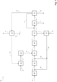
- Figure 1 depicts a block flow diagram of a process 100 according to comparative example 4, wherein a combination of pressure swing adsorption and cryogenic separation is used to produce hydrogen and capture carbon dioxide.
- the tail gas produced in the pressure swing adsorption step contains mainly carbon dioxide, hydrogen, methane and carbon monoxide, and is subject to a tail gas separation step.
- the off-gas produced in the tail gas separation step is routed to a combustion device.
- the heat produced by the combustion device is utilized to produce steam, and the steam is further utilized to generate electrical energy by means of a steam turbine and a generator.
- the electrical energy is converted into heat for the endothermic reaction of the steam methane reforming (SMR) step.
- SMR steam methane reforming
- a hydrocarbon containing feedstock stream here a natural gas stream 1a
- a hydrodesulfurization unit 25 is desulfurized in a hydrodesulfurization unit 25 to afford a desulfurized natural gas stream.
- Said desulfurized natural gas stream is combined with steam stream 13a, which is a partial stream of steam stream 13.
- the resulting combined stream of desulfurized natural gas and steam 2a is converted in a pre-reformer 26 to afford a stream of desulfurized and pre-reformed natural gas, containing mainly methane as the hydrocarbon component.
- Said desulfurized and pre-reformed natural gas stream is combined with steam stream 13b, which is a partial stream of steam stream 13.
- the resulting combined stream of pre-reformed desulfurized natural gas and steam 3a is introduced into an electrically heated SMR unit 27, in the following referred to as e-SMR unit 27.
- the desulfurized and pre-reformed natural gas stream is reformed with steam to afford a stream of synthesis gas 4.
- the reformer tubes (not shown) of the e-SMR unit 27 are heated by means of electrical energy, which is converted into heat.
- the synthesis gas stream 4 is introduced into a water-gas shift unit 28, in which carbon monoxide of the synthesis gas stream 4 is converted with steam into hydrogen and carbon dioxide, to afford a shifted synthesis gas stream 5.
- the shifted synthesis gas stream 5 contains mainly hydrogen and carbon dioxide, but also unconverted carbon monoxide and methane.
- the shifted synthesis gas stream 5 is introduced into a cooling and separation unit 29, in which water contained in the shifted synthesis gas is condensed and withdrawn from the unit 29 as a water condensate stream 11.
- Said water condensate stream 11 is supplied to a boiler 35, which is also supplied with demineralized water via demineralized water stream 12.
- a steam stream 13 is produced, which is divided up into the steam partial streams 13a and 13b, to supply the pre-reformer unit 26 and the e-SMR unit 27 with steam.
- An essentially water-free shifted synthesis gas stream is withdrawn from the cooling and separation unit 29, and a hydrogen rich stream 9 is combined with said stream to afford a hydrogen enriched shifted synthesis gas stream 6.
- This stream 6 is introduced into a hydrogen production unit, here a pressure swing adsorption (PSA) unit 30, in which a hydrogen product stream 7 and a tail gas stream 8 is produced.
- PSA pressure swing adsorption
- the hydrogen product stream 7 is optionally further purified and discharged from the process for further use.
- the tail gas stream 8 which contains carbon dioxide, hydrogen, methane and carbon monoxide, is introduced into a tail gas separation unit 31, in which the tail gas stream is separated into a hydrogen rich stream 9, a carbon dioxide product stream 54, and an off-gas stream 10. How the hydrogen rich stream 9, the carbon dioxide product stream 54, and the off-gas stream 10 can be specifically obtained will be discussed further below in connection with Figure 4.
- the hydrogen rich stream 9 produced in the tail gas separation unit 31 is completely recycled to the dry shifted synthesis gas stream discharged from the cooling and separation unit 29, to afford the hydrogen enriched shifted synthesis gas stream 6.
- the off-gas stream 10 is fed in its entirety to a combustion device, here a fired heater 32, and burned with combustion air to generate heat.
- the heat generated in the fired heater 32 is utilized in the form of two heat streams 17a and 17b. That is, a part of the generated heat is utilized to close the heat balance of the process (stream 17b), and the remaining part is utilized to generate steam by means of a steam system 33.
- a flue gas stream 16 is produced, which mainly comprises carbon dioxide and which is discharged from the fired heater.
- the steam system 33 is also supplied with demineralized water by means of a demineralized water stream 14.
- a steam stream 15 thereby produced in the steam system 33 is fed to a steam turbine and generator unit 34, in which electrical energy is produced in the form of an electrical current 18, which is used for generating heat in the e-SMR unit 27.
- the electrical current 18 produced by the steam turbine and generator unit 34 reduces the amount of electrical power input required for the e-SMR unit. So the main benefit of this approach is the reduction of electricity demand from an external source. However, carbon dioxide emissions are not as much reduced as in the following examples of processes according to the invention.
- Figure 2 depicts a block flow diagram of a process 200 according to one example of the invention.
- shifted and essentially water-free synthesis gas is supplied to an amine wash unit to remove carbon dioxide from the gas mixture.
- the carbon dioxide depleted shifted synthesis gas referred to as the hydrogen raw product stream, is routed to a pressure swing adsorption (PSA) unit, to afford a pure hydrogen product stream and an off-gas stream rich in carbon monoxide and methane.
- PSA pressure swing adsorption
- the major part of the off-gas stream is recycled to the hydrocarbon containing feedstock stream, here a natural gas stream, to afford a combined stream of hydrocarbon feedstock, steam and off-gas.
- Said combined stream is routed to the electrically heated SMR unit (e-SMR unit).
- the remaining portion of the off-gas stream is routed to a fired heater to generate heat, which is utilised to close the heat balance of the overall process.
- a hydrocarbon containing feedstock stream here a natural gas stream 1a
- a compressed off-gas partial stream 21c whereby the off-gas partial stream 21c contains mainly carbon monoxide and methane.
- the combination of said streams afford a combined stream of natural gas and off-gas 1b, which is desulfurized in a hydrodesulfurization unit 25 to afford a desulfurized combined stream of natural gas and off-gas.
- Said stream is combined with steam stream 13a, which is a partial stream of steam stream 13.
- the resulting combined stream 2b of desulfurized natural gas, off-gas and steam is converted in a pre-reformer unit 26 to afford a combined stream of desulfurized and pre-reformed natural gas and off-gas, containing mainly methane as the hydrocarbon component.
- Said stream is combined with steam stream 13b, which is a partial stream of steam stream 13.
- the resulting combined stream 3b of pre-reformed desulfurized natural gas, off-gas and steam, is introduced into an electrically heated SMR unit 27, in the following referred to as e-SMR unit 27.
- the desulfurized and pre-reformed natural gas and off-gas is reformed with steam to afford a stream of synthesis gas 4.
- the reformer tubes (not shown) of the e-SMR unit 27 are heated by means of electrical energy, which is converted into heat. Electrical energy is provided by means of an electric current 19, which comprises electricity from a renewable energy source.
- the synthesis gas stream 4 is introduced into a water-gas shift unit 28, in which carbon monoxide of the synthesis gas stream 4 is converted with steam into hydrogen and carbon dioxide, to afford a shifted synthesis gas stream 5.
- the shifted synthesis gas stream 5 contains mainly hydrogen and carbon dioxide, but also unconverted carbon monoxide and methane.
- the shifted synthesis gas stream 5 is introduced into a cooling and separation unit 29, in which water contained in the shifted synthesis gas is condensed and withdrawn from the unit 29 as a water condensate stream 11.
- Said water condensate stream 11 is supplied to a boiler 35, which is also supplied with demineralized water via demineralized water stream 12.
- a steam stream 35 is produced, which is divided up into the steam partial streams 13a and 13b, to supply the pre-reformer unit 26 and the e-SMR unit 27 with steam.
- An essentially water-free shifted synthesis gas stream 5a is withdrawn from the cooling and separation unit 29 and supplied to a chemical scrubbing unit 43.
- the chemical scrubbing unit 43 at least comprises an absorption column (not shown) and a regenerator (not shown).
- carbon dioxide of the dry shifted synthesis gas stream 5a is chemically absorbed (acid-base interaction) by an aqueous solution of activated methyldiethanolamine (aMDEA).
- aMDEA activated methyldiethanolamine
- a carbon dioxide depleted stream of shifted synthesis gas referred to as hydrogen raw product stream 45, is withdrawn from the absorption column of the chemical scrubbing unit 43 accordingly.
- the laden aMDEA solution i.e.
- the regenerator of the chemical scrubbing unit 43 comprises a reboiler (not shown), through which the rich amine solution is circulated, and which is heated with steam.
- the steam required for the reboiler is produced by the evaporation of boiler feed water, with the thermal energy required for evaporation being provided internally in the process.
- carbon dioxide is desorbed from the rich amine solution, thereby providing a lean amine solution and a carbon dioxide product stream 44.
- the carbon dioxide product stream 44 is withdrawn from the regenerator of the chemical scrubbing unit 43.
- the resulting lean aqueous amine solution (aMDEA solution) is discharged from the regenerator and routed back to the absorption column of the chemical scrubbing unit 43.
- the carbon dioxide stream 44 may be subject to further purification and subsequent compression and sequestration.
- the carbon dioxide depleted shifted synthesis gas stream contains mainly hydrogen as the target product, and carbon monoxide not converted in the shift step, and methane not converted in the steam methane reforming (SMR) step.
- This stream 45 referred to as hydrogen raw product stream, is routed to a hydrogen production unit 46, here a pressure swing adsorption unit. In the pressure swing adsorption unit 46, hydrogen is separated from the hydrogen raw product stream to afford a pure hydrogen product stream 47. Said pure hydrogen stream 47, depending on the specification requirements, may be subject to further purification and is discharged from the process for further use.
- the pressure swing adsorption step in the hydrogen production unit 46 also affords a tail gas stream, which is referred to as the off-gas stream 21 of the hydrogen production step.
- Said off-gas stream contains carbon monoxide and methane as the main components, and possibly residual amounts of hydrogen not separated from the hydrogen raw product stream 45 in the hydrogen production unit 46.
- the off-gas stream 21 is split up into an off-gas partial stream 21a and an off-gas partial stream 21b.
- off-gas partial stream 21a About 60 % of the volume flow of the off-gas stream 21 is routed as off-gas partial stream 21a to a compressor 48, to afford a compressed off-gas partial stream 21c. Said compressed stream 21c is recycled to the natural gas stream 1a to afford the combined stream of natural gas and off-gas 1b.
- a combustion device here a fired heater 32, and burned with combustion air to generate heat.
- the heat generated in the fired heater 32 is utilized in the form a heat stream 20, which is utilized to close the heat balance of the process. Closing the heat balance of the process may involve pre-heating one or several of the streams 1b, 2b, 3b or 4, or generating process steam for the e-SMR unit 27.
- the heat stream 20 is utilised for the generation of steam, which is in turn utilised in the reboiler of the regenerator of the chemical scrubbing unit 43 for the desorption of carbon dioxide from the rich amine solution.
- the combustion device 32 also produces a hot flue gas stream 16.
- the heat stream 20 is derived from the hot flue gas stream 16.
- the material and heat integration according to the example represented by Figure 2 provides a significant reduction of the natural gas feed flow 1a compared to comparative example 4 represented by Figure 1 . Furthermore, it leads to significantly lower direct carbon dioxide emissions, since the amount of fuel sent to the combustion device, i.e. the fired heater 32, is significantly reduced compared to the combustion of PSA tail gas in the conventional SMR setup (comparative example 3), or compared to the combustion of the off-gas stream 10 according to the setup of Figure 1 (comparative example 4).
- e-SMR The electrically heated SMR is referred to as "e-SMR".
- e-SMR (with carbon capture) comparative example 4 ( Figure 1 )
- e-SMR (with carbon capture and off-gas recycle) example ( Figure 2 )
- Natural gas consumption (Nm 3 /Nm 3 H 2 ) 0.335 0.284 Direct CO 2 emissions (kg/Nm 3 H 2 ) 0.250 0.099 Electrical power (kWh/Nm 3 H 2 ) 0.862 1.152 Indirect CO 2 emissions 1 EU 27 basis (kgCO 2 eq/Nm 3 H 2 ) 0.226 0.302 Total CO 2 emissions (direct + indirect EU 27 basis) (kg/Nm 3 H 2 ) 0.476 0.401 Total NG LHV 2 + electric energy input (kWh/Nm 3 H 2 ) 4.340 4.101 1 Carbon intensity of electricity: 262 gCO 2 eq/kWh in EU27 in 2021 2 LHV (lower heating value) of Natural Gas:
- Figure 3 depicts a block flow diagram of a process 300, which represents a partial process of the process according to comparative example 4, and which represents an example of the tail gas separation step of the process according to comparative example 4.
- the tail gas stream 8 is fed to a first compressor stage 36, where it is compressed to medium pressure, for instance a pressure of 5 to 20 bar.
- the resulting compressed tail gas stream 50 is fed to a dryer unit 37, in which any trace of water is removed completely, in order to prevent water from solidifying in downstream steps of the process.
- the dried tail stream thereby obtained is fed to a second compressor stage 38, in which the dried tail gas stream is further compressed to a higher pressure.
- the resulting dried and compressed tail gas stream 52 is fed to a cooling and separation unit 39, in which the tail gas is cooled down to enable condensation of carbon dioxide and separation of the same from the non-condensable gas constituents.
- a liquid carbon dioxide stream 53 thereby obtained is fed to a cryogenic distillation unit 40, in which pure carbon dioxide is obtained as a bottom product.
- Said bottom product, which contains carbon dioxide at the desired purity, is discharged from the cryogenic distillation unit 40 as the carbon dioxide product stream 54.
- the top distillate from the unit 40, the distillation column overhead product stream 58, is recycled to the second compressor stage 38.
- the retentate stream 56 of the first membrane unit 41 is fed to a second membrane unit 42, where most of the remaining carbon dioxide is released as a permeate stream 57, which is recycled back to the second compressor stage 38.
- the retentate of the second membrane unit 42 consists of mostly carbon monoxide and methane, which is discharged from the second membrane unit 42 as the off-gas stream 10.
Landscapes
- Chemical & Material Sciences (AREA)
- Chemical Kinetics & Catalysis (AREA)
- Organic Chemistry (AREA)
- Engineering & Computer Science (AREA)
- Combustion & Propulsion (AREA)
- Inorganic Chemistry (AREA)
- Health & Medical Sciences (AREA)
- General Health & Medical Sciences (AREA)
- Hydrogen, Water And Hydrids (AREA)
Priority Applications (2)
| Application Number | Priority Date | Filing Date | Title |
|---|---|---|---|
| EP23160906.6A EP4428096A1 (fr) | 2023-03-09 | 2023-03-09 | Procédé de production d'hydrogène avec reformage de méthane à la vapeur chauffé électriquement |
| US18/599,736 US20240300816A1 (en) | 2023-03-09 | 2024-03-08 | Process for producing hydrogen with electrically heated steam methane reforming |
Applications Claiming Priority (1)
| Application Number | Priority Date | Filing Date | Title |
|---|---|---|---|
| EP23160906.6A EP4428096A1 (fr) | 2023-03-09 | 2023-03-09 | Procédé de production d'hydrogène avec reformage de méthane à la vapeur chauffé électriquement |
Publications (1)
| Publication Number | Publication Date |
|---|---|
| EP4428096A1 true EP4428096A1 (fr) | 2024-09-11 |
Family
ID=85556676
Family Applications (1)
| Application Number | Title | Priority Date | Filing Date |
|---|---|---|---|
| EP23160906.6A Pending EP4428096A1 (fr) | 2023-03-09 | 2023-03-09 | Procédé de production d'hydrogène avec reformage de méthane à la vapeur chauffé électriquement |
Country Status (2)
| Country | Link |
|---|---|
| US (1) | US20240300816A1 (fr) |
| EP (1) | EP4428096A1 (fr) |
Citations (4)
| Publication number | Priority date | Publication date | Assignee | Title |
|---|---|---|---|---|
| US9908091B2 (en) | 2015-03-31 | 2018-03-06 | Linde Aktiengesellschaft | Furnace with reactor tubes heatable electrically and by means of combustion fuel for steam reforming a feedstock containing hydrocarbon |
| EP3988502A2 (fr) * | 2022-01-24 | 2022-04-27 | Haldor Topsøe A/S | Centrale d'hydrogène avec capture élevée de co2 |
| WO2023281426A1 (fr) * | 2021-07-09 | 2023-01-12 | Agenzia Nazionale Per Le Nuove Tecnologie, L'energia E Lo Sviluppo Economico Sostenibile (Enea) | Méthode et installation pour le traitement de déchets à base de carbone |
| WO2023012836A1 (fr) * | 2021-08-04 | 2023-02-09 | NextChem S.p.A. | Procédé de production d'hydrogène couplé à la capture de co2 |
-
2023
- 2023-03-09 EP EP23160906.6A patent/EP4428096A1/fr active Pending
-
2024
- 2024-03-08 US US18/599,736 patent/US20240300816A1/en active Pending
Patent Citations (4)
| Publication number | Priority date | Publication date | Assignee | Title |
|---|---|---|---|---|
| US9908091B2 (en) | 2015-03-31 | 2018-03-06 | Linde Aktiengesellschaft | Furnace with reactor tubes heatable electrically and by means of combustion fuel for steam reforming a feedstock containing hydrocarbon |
| WO2023281426A1 (fr) * | 2021-07-09 | 2023-01-12 | Agenzia Nazionale Per Le Nuove Tecnologie, L'energia E Lo Sviluppo Economico Sostenibile (Enea) | Méthode et installation pour le traitement de déchets à base de carbone |
| WO2023012836A1 (fr) * | 2021-08-04 | 2023-02-09 | NextChem S.p.A. | Procédé de production d'hydrogène couplé à la capture de co2 |
| EP3988502A2 (fr) * | 2022-01-24 | 2022-04-27 | Haldor Topsøe A/S | Centrale d'hydrogène avec capture élevée de co2 |
Also Published As
| Publication number | Publication date |
|---|---|
| US20240300816A1 (en) | 2024-09-12 |
Similar Documents
| Publication | Publication Date | Title |
|---|---|---|
| US20260116748A1 (en) | Method and system for producing hydrogen from ammonia cracking | |
| EP2516327B1 (fr) | Conversion d'hydrocarbures en dioxyde de carbone et en énergie électrique | |
| EP2516326B1 (fr) | Conversion d'hydrocarbures en dioxyde de carbone et en énergie électrique | |
| US20230174378A1 (en) | Process for producing hydrogen | |
| EA008048B1 (ru) | Получение углеводородов путём риформинга с водяным паром и реакции фишера-тропша | |
| KR20210130156A (ko) | 스팀 메탄 개질에 의한 합성 가스 생성 | |
| JP2004530272A (ja) | 二酸化炭素除去と一体化した燃料処理装置、燃料電池スタック及び廃ガス酸化装置 | |
| EP4522584B1 (fr) | Procédé de synthèse de méthanol | |
| US9266805B2 (en) | System and method for producing gasoline or dimethyl ether | |
| US20240300815A1 (en) | Process for producing hydrogen with electrically heated steam methane reforming | |
| KR20250128296A (ko) | 수소를 생성하기 위한 공정 | |
| EP4428096A1 (fr) | Procédé de production d'hydrogène avec reformage de méthane à la vapeur chauffé électriquement | |
| CN120826385A (zh) | 用于合成甲醇的方法 | |
| CN120225637A (zh) | 将h2和含co2的尾气转化为合成燃料 | |
| EP4676876A1 (fr) | Procédé de production d'hydrogène avec reformage de méthane à la vapeur chauffé électriquement | |
| US20230264145A1 (en) | Improving the purity of a CO2-rich stream | |
| EP4436914A1 (fr) | Amélioration de l'efficacité énergétique d'un procédé et installation de production d'hydrogène | |
| WO2025068673A1 (fr) | Procédé de synthèse de méthanol avec préparation et traitement de gaz de synthèse optimisés |
Legal Events
| Date | Code | Title | Description |
|---|---|---|---|
| PUAI | Public reference made under article 153(3) epc to a published international application that has entered the european phase |
Free format text: ORIGINAL CODE: 0009012 |
|
| STAA | Information on the status of an ep patent application or granted ep patent |
Free format text: STATUS: THE APPLICATION HAS BEEN PUBLISHED |
|
| AK | Designated contracting states |
Kind code of ref document: A1 Designated state(s): AL AT BE BG CH CY CZ DE DK EE ES FI FR GB GR HR HU IE IS IT LI LT LU LV MC ME MK MT NL NO PL PT RO RS SE SI SK SM TR |
|
| STAA | Information on the status of an ep patent application or granted ep patent |
Free format text: STATUS: REQUEST FOR EXAMINATION WAS MADE |
|
| 17P | Request for examination filed |
Effective date: 20250311 |