EP4428451A1 - Procédé de gestion de chaleur et d'énergie dans un réseau thermique - Google Patents
Procédé de gestion de chaleur et d'énergie dans un réseau thermique Download PDFInfo
- Publication number
- EP4428451A1 EP4428451A1 EP24162329.7A EP24162329A EP4428451A1 EP 4428451 A1 EP4428451 A1 EP 4428451A1 EP 24162329 A EP24162329 A EP 24162329A EP 4428451 A1 EP4428451 A1 EP 4428451A1
- Authority
- EP
- European Patent Office
- Prior art keywords
- heat
- transfer medium
- heat transfer
- pump
- consumer
- Prior art date
- Legal status (The legal status is an assumption and is not a legal conclusion. Google has not performed a legal analysis and makes no representation as to the accuracy of the status listed.)
- Pending
Links
- 238000000034 method Methods 0.000 title claims abstract description 39
- 238000010438 heat treatment Methods 0.000 claims abstract description 38
- 238000010521 absorption reaction Methods 0.000 claims abstract description 37
- 238000005338 heat storage Methods 0.000 claims description 27
- 230000017525 heat dissipation Effects 0.000 claims description 13
- 238000000605 extraction Methods 0.000 claims description 6
- 239000002826 coolant Substances 0.000 claims description 3
- 239000007789 gas Substances 0.000 description 16
- 230000005611 electricity Effects 0.000 description 6
- 238000011161 development Methods 0.000 description 5
- 230000018109 developmental process Effects 0.000 description 5
- 230000008901 benefit Effects 0.000 description 2
- 238000010586 diagram Methods 0.000 description 2
- 238000002156 mixing Methods 0.000 description 2
- 230000001105 regulatory effect Effects 0.000 description 2
- 238000011144 upstream manufacturing Methods 0.000 description 2
- XLYOFNOQVPJJNP-UHFFFAOYSA-N water Substances O XLYOFNOQVPJJNP-UHFFFAOYSA-N 0.000 description 2
- 238000009833 condensation Methods 0.000 description 1
- 230000005494 condensation Effects 0.000 description 1
- 230000001419 dependent effect Effects 0.000 description 1
- 238000001704 evaporation Methods 0.000 description 1
- 230000008020 evaporation Effects 0.000 description 1
- 239000013529 heat transfer fluid Substances 0.000 description 1
- 230000001172 regenerating effect Effects 0.000 description 1
- 230000008929 regeneration Effects 0.000 description 1
- 238000011069 regeneration method Methods 0.000 description 1
- 230000006641 stabilisation Effects 0.000 description 1
- 238000011105 stabilization Methods 0.000 description 1
- 230000000087 stabilizing effect Effects 0.000 description 1
Images

Classifications
-
- F—MECHANICAL ENGINEERING; LIGHTING; HEATING; WEAPONS; BLASTING
- F24—HEATING; RANGES; VENTILATING
- F24D—DOMESTIC- OR SPACE-HEATING SYSTEMS, e.g. CENTRAL HEATING SYSTEMS; DOMESTIC HOT-WATER SUPPLY SYSTEMS; ELEMENTS OR COMPONENTS THEREFOR
- F24D3/00—Hot-water central heating systems
- F24D3/18—Hot-water central heating systems using heat pumps
-
- F—MECHANICAL ENGINEERING; LIGHTING; HEATING; WEAPONS; BLASTING
- F24—HEATING; RANGES; VENTILATING
- F24D—DOMESTIC- OR SPACE-HEATING SYSTEMS, e.g. CENTRAL HEATING SYSTEMS; DOMESTIC HOT-WATER SUPPLY SYSTEMS; ELEMENTS OR COMPONENTS THEREFOR
- F24D11/00—Central heating systems using heat accumulated in storage masses
- F24D11/02—Central heating systems using heat accumulated in storage masses using heat pumps
- F24D11/0214—Central heating systems using heat accumulated in storage masses using heat pumps water heating system
-
- F—MECHANICAL ENGINEERING; LIGHTING; HEATING; WEAPONS; BLASTING
- F24—HEATING; RANGES; VENTILATING
- F24D—DOMESTIC- OR SPACE-HEATING SYSTEMS, e.g. CENTRAL HEATING SYSTEMS; DOMESTIC HOT-WATER SUPPLY SYSTEMS; ELEMENTS OR COMPONENTS THEREFOR
- F24D17/00—Domestic hot-water supply systems
- F24D17/02—Domestic hot-water supply systems using heat pumps
-
- F—MECHANICAL ENGINEERING; LIGHTING; HEATING; WEAPONS; BLASTING
- F24—HEATING; RANGES; VENTILATING
- F24D—DOMESTIC- OR SPACE-HEATING SYSTEMS, e.g. CENTRAL HEATING SYSTEMS; DOMESTIC HOT-WATER SUPPLY SYSTEMS; ELEMENTS OR COMPONENTS THEREFOR
- F24D19/00—Details
- F24D19/10—Arrangement or mounting of control or safety devices
- F24D19/1006—Arrangement or mounting of control or safety devices for water heating systems
- F24D19/1009—Arrangement or mounting of control or safety devices for water heating systems for central heating
- F24D19/1039—Arrangement or mounting of control or safety devices for water heating systems for central heating the system uses a heat pump
-
- F—MECHANICAL ENGINEERING; LIGHTING; HEATING; WEAPONS; BLASTING
- F25—REFRIGERATION OR COOLING; COMBINED HEATING AND REFRIGERATION SYSTEMS; HEAT PUMP SYSTEMS; MANUFACTURE OR STORAGE OF ICE; LIQUEFACTION SOLIDIFICATION OF GASES
- F25B—REFRIGERATION MACHINES, PLANTS OR SYSTEMS; COMBINED HEATING AND REFRIGERATION SYSTEMS; HEAT PUMP SYSTEMS
- F25B30/00—Heat pumps
- F25B30/02—Heat pumps of the compression type
-
- F—MECHANICAL ENGINEERING; LIGHTING; HEATING; WEAPONS; BLASTING
- F24—HEATING; RANGES; VENTILATING
- F24D—DOMESTIC- OR SPACE-HEATING SYSTEMS, e.g. CENTRAL HEATING SYSTEMS; DOMESTIC HOT-WATER SUPPLY SYSTEMS; ELEMENTS OR COMPONENTS THEREFOR
- F24D2220/00—Components of central heating installations excluding heat sources
- F24D2220/02—Fluid distribution means
- F24D2220/0235—Three-way-valves
Definitions
- the invention relates to a method for heat and power management in a heating network and to a heating network having a heat transfer circuit in which a heat pump, a heat storage device and at least one heat source and one heat consumer are integrated.
- the flow and return flow usually have the same volume flow of a heat transfer medium and only moderate temperature differences due to a closed heat transfer medium circuit.
- the potential of a heat pump operating with a transcritical process cannot therefore be exploited or can only be exploited to a limited extent with known systems. In fact, the efficiency would be poor, making such use unprofitable.
- a key advantage of a heat pump operating with a transcritical process by using non-condensing gases is that there is no need to pay attention to pressure and temperature restrictions during evaporation and condensation of a coolant.
- a heat pump operating with a transcritical process can achieve relatively high temperatures, such as those required for the heat supply of old buildings that cannot be adequately insulated due to their structural integrity or protection status.
- the object of the invention is therefore to provide a method and a heating network into which heat pumps operating with a transcritical process can be integrated.
- the method for heat and power management in a heating network is characterized according to the invention in that heat transfer medium circulating in the heating network is fed via both a heat output side and a heat absorption side of a heat pump, in particular one with a heat pump operated in a transcritical process, that the heat transfer medium flowing to the heat output side of the heat pump is passed through a distributor at which the heat transfer medium can be divided into at least two partial flows depending on a respective operating mode, that a first partial flow of the heat transfer medium is fed to the heat output side of the heat pump and heated and a second partial flow of the heat transfer medium is passed into a bypass, that the heat transfer medium is fed to at least one heat consumer after flowing through the heat output side, that the heat transfer medium leaving the heat consumer is stored in a heat accumulator and that the second partial flow of the heat transfer medium passed into the bypass is passed on the heat output side of the heat pump past the at least one heat consumer and the heat accumulator.
- the heating network can thus be managed according to different operating modes and combine the different, aforementioned requirements that result from the use of heat pumps operating according to a transcritical process.
- the flow rate of the heat transfer medium to be fed to the heat dissipation side can be influenced.
- the heat transfer medium is heated up more, whereby the temperature of the heat transfer medium leaving the heat dissipation side can be controlled specifically via the flow rate of the heat transfer medium.
- the heat consumer can thus benefit from this and due to the possible high Temperatures of the gas of the heat pump operated with a transcritical process provide a heat transfer medium with a relatively high temperature level, which is also suitable, among other things, for supplying old buildings with heat.
- Another way to control the heating network is to increase the speed of the compressor.
- the temperature of the heat transfer medium reaching the heat consumer cannot then be controlled. Changing the speed of the compressor can therefore only be a supplementary measure.
- the two partial flows are combined again to form a single volume flow of the heat transfer medium, so that a hydraulically closed heat transfer circuit of the circulating heat transfer medium is formed.
- the heat required for the heat pump process is therefore taken from the entire volume flow of the heat transfer medium, which is cooled down.
- the heat transfer medium flows to at least one heat source integrated into the heat network after flowing through the heat absorption side of the heat pump.
- the heat required can be supplied to the heat transfer circuit via this heat source in order to maintain it and to compensate for the heat extracted by the heat consumer or to store heat provided by the heat source.
- the heat transfer medium flowing to the heat source advantageously has the lowest temperature of the heat transfer medium circulating in the heat transfer circuit in order to be able to use low-temperature heat sources in particular.
- the heat transfer medium absorbs heat energy from the at least one heat source.
- This operating mode can be referred to as normal operation, in which heat energy provided by the heat source is used.
- the heat source is advantageously a regenerative heat source, for example domestic water.
- the first partial flow supplied to the heat output side of the heat pump experiences a further increase in temperature and, after flowing through the heat consumer, is fed into the heat storage unit at a temperature above the second partial flow fed through the bypass, while heat transfer medium from the heat storage unit at a temperature that lies between the temperature from the return of the at least one heat consumer and the second partial flow is mixed with the second partial flow fed through the bypass to form the heat transfer medium to be fed to the heat absorption side of the heat pump.
- the heat transfer medium taken from the heat storage unit thus increases the temperature of the heat transfer medium to be fed to the heat absorption side and accordingly improves the efficiency of the heat pump operated with a transcritical process.
- This mode of operation can be maintained as long as the heat storage has capacity. As soon as the heat storage is exhausted, i.e. no more heat can be stored, a second mode of operation must be used.
- the heat transfer medium is advantageously guided past the heat source without absorbing heat energy as soon as the temperature of the heat transfer medium to be taken from the heat storage exceeds the temperature of the second partial flow passed through the bypass. This makes it possible to regenerate the heat storage by not supplying heat to the heat transfer circuit and at the same time the heat consumer continues to take heat energy from the heat transfer circuit.
- Management of the heating network also enables the stabilization of an electricity network.
- the heat pump can be operated at full load or at least at a higher load than required by the heat consumer or the heating network itself if there is a surplus of electricity, whereby on the one hand greater electricity consumption is generated and on the other hand heat is stored.
- stored heat energy is supplied to the heat consumer when the heat pump is switched off or the heat pump's output is throttled, by taking the heat transfer medium from the heat storage unit. Inefficiencies in terms of heat utilization are neglected in favor of the primary goal of stabilizing the electricity network.
- a further development provides that a coolant circulating in the heat pump first releases heat energy in a gas cooler of the heat pump to at least one heat transfer medium of at least one cascaded heat transfer circuit before the heat energy provided at the gas cooler is transferred to the heat transfer medium.
- the high temperatures provided by the gas cooler by the transcritically operated heat pump can thus be hydraulically regulated down so that the heat transfer medium in the heat transfer circuit is brought to a lower temperature level.
- the invention also relates to a heat network for heat and power management, comprising a heat transfer circuit in which a heat pump, a heat storage unit and at least one heat source and one heat consumer are integrated.
- This heat network is characterized according to the invention in that the heat pump, the in particular a heat pump operated with a transcritical process, both with its heat emission side and with its heat absorption side being connected to the heat transfer circuit, that a distributor is connected upstream of the heat emission side in the flow direction of a heat transfer medium guided in the heat transfer circuit, at which distributor the heat transfer circuit branches into a heat emission side supply line and a bypass, that at least one heat consumer is connected downstream of the heat emission side of the heat pump in the flow direction of the heat transfer medium supplied to the heat emission side via the heat emission side supply line, that a heat accumulator is connected to the heat consumer in the flow direction of the heat transfer medium and that the bypass guides the heat transfer circuit past the heat emission side, the at least one heat consumer and the heat accumulator.
- the distributor thus enables hydraulic control of the heating network by dividing the heat transfer medium circulating in the heat transfer circuit into two partial flows, one of which is brought to a temperature specified by the heat consumer.
- the temperature can be specifically influenced and controlled with the flow rate of the heat transfer medium on the heat output side.
- the temperatures that can be provided on the heat output side by the transcritical operation of the heat pump ensure that the high temperatures required for old buildings, for example, can also be provided with the heating network according to the invention.
- a high efficiency of the heating network is achieved according to a further development by merging the bypass with a heat storage extraction line to form a heat absorption side supply line, whereby the heat absorption side supply line flows into the heat absorption side of the heat pump.
- Cold heat transfer medium flowing in from the heat storage always has a higher temperature than the heat transfer medium flowing through the bypass, so that the mixing of the two partial flows results in a temperature increase compared to the second partial flow flowing through the bypass.
- the heat transfer medium flowing to the heat absorption side therefore advantageously has the highest possible temperature and can be used particularly effectively on the heat pump to operate the transcritical process.
- the at least one heat source is integrated into the heat transfer medium circuit downstream of the heat absorption side of the heat pump between the heat absorption side and the distributor. After heat has been extracted from the heat transfer medium on the heat absorption side of the heat pump, the heat transfer medium then flows to the heat source at the lowest possible temperature in the heat transfer medium circuit and can also extract heat from low-temperature heat sources, such as domestic water, which can be used in the heating network.
- a heat source bypass is provided in the heat transfer circuit parallel to the heat source.
- This heat source bypass is required to decouple the heat source from the heat transfer circuit in terms of flow and to allow heat transfer fluid to flow past the heat source.
- One operating mode in which the heat source must be decoupled from the heat transfer circuit concerns, for example, regeneration of the heat storage unit. This must be carried out as soon as the entire heat storage unit has the highest possible temperature of the heat transfer circuit and no more heat can be stored.
- a heat transfer line leading from the heat consumer branches into a storage supply line and a bypass supply line.
- the only slightly cooled heat transfer medium flowing away from the heat consumer can not only be introduced into the heat storage and stored through this additional branching, but can also be fed directly to the bypass.
- the heating network is preferably designed for heat consumers who require a high temperature level. For such a heat consumer with a required high temperature level, the heat transfer medium at the gas cooler is brought to a temperature between 50 °C and 110 °C, in particular 75 °C. Such a heating network is then designed in particular for old buildings.
- the heat pump operating with a transcritical process is to be modified in such a way that low-temperature heat networks, such as those used in known applications of heat pumps, can also be combined with a heat pump operating according to a transcritical process.
- the heat pump has a gas cooler which is connected in a heat-transfer manner to the heat dissipation side integrated into the heat transfer circuit via at least one cascaded heat transfer circuit.
- the high temperatures present at the gas cooler due to the process can then be hydraulically regulated down.
- the heat transfer medium is then heated accordingly on the heat dissipation side of the heat pump to an overall lower temperature level.
- Fig.1 shows a heating network according to the invention having a heat transfer circuit 1 for a heat transfer medium circulating therein with a heat pump 2, in particular a heat pump 2 operated with a transcritical process, a heat consumer 3, a heat storage device 4 and a heat source 5.
- the heat pump 2 is integrated into the heat transfer circuit 1 in a heat-transfer manner with both its heat output side 2a and its heat absorption side 2b, the heat output side 2a being formed by a gas cooler.
- the heat transfer circuit 1 also has a distributor 6, at which the heat transfer circuit 1 branches into a heat output side supply line 7 and a bypass 8.
- the heat output side supply line 7 leads to the heat output side 2a of the heat pump 2 and flows through the gas cooler.
- the heat output side 2a is followed in the flow direction of the heat transfer medium by the heat consumer 3, to which heat is emitted according to an existing requirement.
- the heat transfer medium reaches the heat storage tank 4 from the heat consumer 3.
- a heat transfer line 9 branches off from the heat consumer 3 and branches into a storage tank supply line 10 leading to the heat storage tank 4 and a bypass supply line 11 leading to the bypass 8.
- the bypass 8 is divided into two sections 8', 8" of which a first section 8' passes the heat output side 2a of the heat pump 2, the heat consumer 3 and the heat storage 4 to the inlet Bypass supply line 11 and a second section 8" from the bypass supply line 11 to a heat storage extraction line 12.
- the heat storage extraction line 12 and the bypass 8 then together form a heat absorption side supply line 13 in which the heat transfer medium flows in the direction of the heat absorption side 2b of the heat pump 2.
- the at least one heat source 5 is connected downstream of the heat absorption side 2b of the heat pump 2 in the flow direction of the heat transfer medium and is integrated into the heat transfer medium circuit 1 between the heat absorption side 2b and the distributor 6.
- a heat source bypass 14 is arranged parallel to the heat source 5 and can be shut off with a shut-off valve 15.
- a return line 16 of the heat transfer medium circuit 1 leading away from the heat absorption side 2b branches off accordingly in the flow direction of the heat transfer medium upstream of the heat source 5 into a heat source supply line 17 and the heat source bypass 14.
- the heat source supply line 17 and the heat source bypass 14 are brought together again to form a common feed pump supply line 18, which opens into a feed pump 19 of the heat transfer medium circuit.
- a distributor supply line 20 branches off from the feed pump 19, which connects the feed pump 19 to the distributor 6 in a media-conducting manner.
- An additional heat source 21 and an additional cold source 22 can be taken, which are each connected to the return line 16 via a heat exchanger, pump and shut-off valve.
- a first operating mode which can also be referred to as normal operation, the heat transfer medium flows through the heat source 5 and absorbs the heat energy provided by the heat source 5.
- the heat transfer medium flows via the feed pump feed line 18, which Feed pump 19 and the distributor feed line 20 in the direction of the distributor 6.
- the heat transfer medium is divided into a first partial flow and a second partial flow.
- the first partial flow flows via the heat output side feed line 7 to the heat output side 2a of the heat pump 2, is heated again on the heat output side 2a of the heat pump 2 before the first partial flow reaches the heat consumer 3.
- temperatures of the heat transfer medium on the heat output side 2a of between 50 °C and 110 °C, in particular 75 °C, are reached.
- the heat transfer medium which is still quite warm after leaving the heat consumer 3, is then fed to the heat accumulator 4 via the heat transfer line 9 and the storage feed line 10 and stored therein.
- the heat transfer medium fed to the heat accumulator 4 has at least a temperature that is above the second partial flow passed through the bypass 8.
- the second partial flow is guided in the bypass 8 past the heat output side 2a, the heat consumer 3 and the heat accumulator 4 to the heat accumulator extraction line 12 which opens into the bypass 8.
- the heat accumulator extraction line 12 and the bypass 8 then form the heat absorption side supply line 13 in which the second partial flow and cold heat transfer medium fed from the heat accumulator 4 combine to form the heat transfer medium flowing to the heat absorption side 2b.
- heat is then extracted from the heat transfer medium in accordance with the generally known principle of a heat pump 2.
- the cooled heat transfer medium then flows back to the heat source 5 via the return line 16 of the heat transfer circuit 1. This operating mode is maintained as long as cold heat transfer medium can be extracted from the heat accumulator 4. As soon as the heat accumulator 4 is exhausted, a second operating mode is switched to.
- This second mode of operation is characterized by the fact that the heat storage unit 4 is regenerated, whereby stored heat is removed from it.
- the heat transfer medium is now passed through the heat source bypass 14 instead of absorbing heat energy from the heat source 5, so that the heat source 5 is fluidically separated from the heat transfer circuit 1. Heat is thus extracted from the heat transfer medium on the heat absorption side 2b and fed back into the first partial flow flowing through the heat emission side 2a. Heat is then extracted from the first partial flow by the heat consumer 3.
- the speed at which the heat network is regenerated is therefore directly dependent on the amount of heat extracted from the heat consumer 3.
- Other operating modes of the heating network can be used to support the network stability of a connected power network.
- the heat pump 2 In the event of an excess of electricity, the heat pump 2 is switched on regardless of the heat demand of the heat consumer 3. In order to generate a high level of electricity consumption in the heating network, the heat pump 2 goes into full load operation or at least a required load operation. Depending on the heat demand of the consumer 3, heat must then be stored in the heat storage unit 4, with the heat transfer medium flowing through the heating network in accordance with normal operation.
- the heat pump 2 is throttled or switched off and stored heat is taken from the heat accumulator 4 in order to supply heat to the at least one heat consumer 3.
- the heat transfer medium then flows, without heat being transferred, one after the other through the heat absorption side 2b and the heat emission side 2a of the heat pump 2. Since the heat transfer medium stored in the heat accumulator 4 has a higher temperature level than the heat source 5, the heat transfer medium is passed through the heat source bypass 14 in this operating mode.
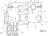
- FIG.2 A further embodiment of the invention is described in Fig.2 This differs from the version according to Fig.1 by the fact that the heat pump 2 ⁇ is supplemented by an additional heat transfer circuit 2c'.
- This heat transfer circuit 2c' is connected between a gas cooler 2d' and the heat output side 2a' of the heat pump 2 ⁇ .
- the high temperatures that necessarily occur at the gas cooler 2d' in a heat pump 2 ⁇ operated with a transcritical process can be cooled down in this way.
- the heat output side 2a' and the heat absorption side 2b' are as in the embodiment according to Fig.1 integrated into the otherwise identically structured heating network.
Landscapes
- Engineering & Computer Science (AREA)
- Physics & Mathematics (AREA)
- Thermal Sciences (AREA)
- Mechanical Engineering (AREA)
- General Engineering & Computer Science (AREA)
- Chemical & Material Sciences (AREA)
- Combustion & Propulsion (AREA)
- Central Heating Systems (AREA)
Applications Claiming Priority (1)
| Application Number | Priority Date | Filing Date | Title |
|---|---|---|---|
| DE102023106013.9A DE102023106013A1 (de) | 2023-03-10 | 2023-03-10 | Verfahren zum Wärme- und Strommanagement in einem Wärmenetz |
Publications (1)
| Publication Number | Publication Date |
|---|---|
| EP4428451A1 true EP4428451A1 (fr) | 2024-09-11 |
Family
ID=90363401
Family Applications (1)
| Application Number | Title | Priority Date | Filing Date |
|---|---|---|---|
| EP24162329.7A Pending EP4428451A1 (fr) | 2023-03-10 | 2024-03-08 | Procédé de gestion de chaleur et d'énergie dans un réseau thermique |
Country Status (2)
| Country | Link |
|---|---|
| EP (1) | EP4428451A1 (fr) |
| DE (1) | DE102023106013A1 (fr) |
Citations (6)
| Publication number | Priority date | Publication date | Assignee | Title |
|---|---|---|---|---|
| WO2010102626A2 (fr) * | 2009-03-10 | 2010-09-16 | Danfoss A/S | Système de chauffage |
| US20120000236A1 (en) * | 2009-04-13 | 2012-01-05 | Panasonic Corporation | Heat pump heating system |
| EP3214377A1 (fr) * | 2016-02-27 | 2017-09-06 | Wolfgang Jaske | Procédé de fonctionnement d'une installation de chauffage comprenant une chaudière à condensation et installation de chauffage |
| WO2019087037A1 (fr) * | 2017-10-30 | 2019-05-09 | Frigel Firenze S.P.A. | Système thermodynamique pour équilibrer des charges thermiques dans des installations et procédés industriels, et méthode associé |
| WO2020245304A1 (fr) * | 2019-06-07 | 2020-12-10 | Peter Wolf | Procédé pour faire fonctionner une installation de chauffage comprenant une pompe de chaleur et installation de chauffage |
| EP3835666A1 (fr) * | 2019-12-13 | 2021-06-16 | Wolfgang Jaske und Dr. Peter Wolf GbR | Système de bâtiment destiné à la climatisation et à l'approvisionnement en chaleur |
-
2023
- 2023-03-10 DE DE102023106013.9A patent/DE102023106013A1/de active Pending
-
2024
- 2024-03-08 EP EP24162329.7A patent/EP4428451A1/fr active Pending
Patent Citations (6)
| Publication number | Priority date | Publication date | Assignee | Title |
|---|---|---|---|---|
| WO2010102626A2 (fr) * | 2009-03-10 | 2010-09-16 | Danfoss A/S | Système de chauffage |
| US20120000236A1 (en) * | 2009-04-13 | 2012-01-05 | Panasonic Corporation | Heat pump heating system |
| EP3214377A1 (fr) * | 2016-02-27 | 2017-09-06 | Wolfgang Jaske | Procédé de fonctionnement d'une installation de chauffage comprenant une chaudière à condensation et installation de chauffage |
| WO2019087037A1 (fr) * | 2017-10-30 | 2019-05-09 | Frigel Firenze S.P.A. | Système thermodynamique pour équilibrer des charges thermiques dans des installations et procédés industriels, et méthode associé |
| WO2020245304A1 (fr) * | 2019-06-07 | 2020-12-10 | Peter Wolf | Procédé pour faire fonctionner une installation de chauffage comprenant une pompe de chaleur et installation de chauffage |
| EP3835666A1 (fr) * | 2019-12-13 | 2021-06-16 | Wolfgang Jaske und Dr. Peter Wolf GbR | Système de bâtiment destiné à la climatisation et à l'approvisionnement en chaleur |
Also Published As
| Publication number | Publication date |
|---|---|
| DE102023106013A1 (de) | 2024-09-12 |
Similar Documents
| Publication | Publication Date | Title |
|---|---|---|
| EP3269002B1 (fr) | Dispositiv de refroidissement pour refroidir une pile à combustible | |
| DE112008003700B4 (de) | Vorrichtung zur Steigerung der Heiz- und Kühlleistung einer Wärmepumpe in der Wärmerückgewinnung in Lüftungsgeräten | |
| EP2784400B1 (fr) | Procédé et dispositif d'injection de chaleur depuis un réseau de chaleur | |
| DE102021127770A1 (de) | Thermomanagementsystem für ein Kraftfahrzeug und Kraftfahrzeug mit einem solchen | |
| WO2019215240A1 (fr) | Système de chauffage et/ou de production d'eau chaude sanitaire | |
| DE102004005935B4 (de) | Verfahren zum Kaltstarten eines Brennstoffzellensystems bei Minustemperaturen | |
| EP2458304A2 (fr) | Installation de pompe à chaleur comprenant une pompe à chaleur et procédé de fonctionnement d'une telle installation de pompe à chaleur | |
| EP4249813A1 (fr) | Procédé de gestion d'énergie d'un réseau thermique | |
| DE102012014110A1 (de) | Brennstoffzellensystem | |
| EP0893872A2 (fr) | Système de refroidissement pour générateur | |
| DE10155508C5 (de) | Verfahren und Vorrichtung zur Erzeugung von elektrischer Energie | |
| DE102020201455A1 (de) | System sowie Verfahren zur Klimatisierung eines Fahrzeuginnenraums und gleichzeitigen Kühlung einer Fahrzeugbatterie für ein elektrisches Fahrzeug | |
| EP4428451A1 (fr) | Procédé de gestion de chaleur et d'énergie dans un réseau thermique | |
| DE102021118975B4 (de) | Kühlsystem, Brennstoffzellenfahrzeug und Verfahren zum Betreiben eines Kühlsystems | |
| EP3586072B1 (fr) | Dispositif et procédé pour accroître le rendement thermique d'une source de chaleur | |
| WO2024056343A1 (fr) | Procédé et dispositif d'intégration de chaleur dans un réseau de chauffage urbain | |
| DE102011053322A1 (de) | Verfahren und Vorrichtung zur Speicherung und Rückgewinnung von thermischer Energie | |
| WO2003052853A2 (fr) | Systeme de cellule electrochimique comportant un dispositif de recuperation d'eau d'echappement | |
| WO2018029371A1 (fr) | Échangeur de chaleur destiné à être utilisé dans une partie chaude d'une centrale de stockage d'énergie par air liquide, partie chaude et procédé permettant de faire fonctionner ledit échangeur de chaleur dans ladite partie chaude | |
| WO2022174869A1 (fr) | Procédé pour charger un accumulateur d'eau chaude au niveau d'une connexion de chauffage urbain, et agencement pour charger un accumulateur d'eau chaude, et pompe à chaleur pour charger un accumulateur d'eau chaude | |
| DE102012209480B4 (de) | Hochdruck-Pumpsystem zur Förderung heißer Medien | |
| AT524304B1 (de) | Verdampfervorrichtung für ein Brennstoffzellensystem | |
| DE102008035897A1 (de) | Brennstoffzellensystem und Verfahren zum Betreiben eines solchen | |
| DE102022209850A1 (de) | Wärmepumpenanordnung, Verfahren zu deren Betrieb und damit ausgestattetes Gebäude | |
| DE102023209936A1 (de) | Verfahren und Vorrichtung zum Speichern von Brenngas, insbesondere von Wasserstoff |
Legal Events
| Date | Code | Title | Description |
|---|---|---|---|
| PUAI | Public reference made under article 153(3) epc to a published international application that has entered the european phase |
Free format text: ORIGINAL CODE: 0009012 |
|
| STAA | Information on the status of an ep patent application or granted ep patent |
Free format text: STATUS: THE APPLICATION HAS BEEN PUBLISHED |
|
| AK | Designated contracting states |
Kind code of ref document: A1 Designated state(s): AL AT BE BG CH CY CZ DE DK EE ES FI FR GB GR HR HU IE IS IT LI LT LU LV MC ME MK MT NL NO PL PT RO RS SE SI SK SM TR |
|
| STAA | Information on the status of an ep patent application or granted ep patent |
Free format text: STATUS: REQUEST FOR EXAMINATION WAS MADE |
|
| 17P | Request for examination filed |
Effective date: 20250219 |