EP4428501B1 - Dispositif de mesure de débit - Google Patents
Dispositif de mesure de débit Download PDFInfo
- Publication number
- EP4428501B1 EP4428501B1 EP23161323.3A EP23161323A EP4428501B1 EP 4428501 B1 EP4428501 B1 EP 4428501B1 EP 23161323 A EP23161323 A EP 23161323A EP 4428501 B1 EP4428501 B1 EP 4428501B1
- Authority
- EP
- European Patent Office
- Prior art keywords
- flow
- section
- transport direction
- fluid
- measurement apparatus
- Prior art date
- Legal status (The legal status is an assumption and is not a legal conclusion. Google has not performed a legal analysis and makes no representation as to the accuracy of the status listed.)
- Active
Links
Images

Classifications
-
- G—PHYSICS
- G01—MEASURING; TESTING
- G01F—MEASURING VOLUME, VOLUME FLOW, MASS FLOW OR LIQUID LEVEL; METERING BY VOLUME
- G01F1/00—Measuring the volume flow or mass flow of fluid or fluent solid material wherein the fluid passes through a meter in a continuous flow
- G01F1/66—Measuring the volume flow or mass flow of fluid or fluent solid material wherein the fluid passes through a meter in a continuous flow by measuring frequency, phase shift or propagation time of electromagnetic or other waves, e.g. using ultrasonic flowmeters
- G01F1/662—Constructional details
-
- G—PHYSICS
- G01—MEASURING; TESTING
- G01F—MEASURING VOLUME, VOLUME FLOW, MASS FLOW OR LIQUID LEVEL; METERING BY VOLUME
- G01F1/00—Measuring the volume flow or mass flow of fluid or fluent solid material wherein the fluid passes through a meter in a continuous flow
- G01F1/05—Measuring the volume flow or mass flow of fluid or fluent solid material wherein the fluid passes through a meter in a continuous flow by using mechanical effects
- G01F1/20—Measuring the volume flow or mass flow of fluid or fluent solid material wherein the fluid passes through a meter in a continuous flow by using mechanical effects by detection of dynamic effects of the flow
- G01F1/32—Measuring the volume flow or mass flow of fluid or fluent solid material wherein the fluid passes through a meter in a continuous flow by using mechanical effects by detection of dynamic effects of the flow using swirl flowmeters
- G01F1/325—Means for detecting quantities used as proxy variables for swirl
- G01F1/3282—Means for detecting quantities used as proxy variables for swirl for detecting variations in infrasonic, sonic or ultrasonic waves, due to modulation by passing through the swirling fluid
-
- G—PHYSICS
- G01—MEASURING; TESTING
- G01F—MEASURING VOLUME, VOLUME FLOW, MASS FLOW OR LIQUID LEVEL; METERING BY VOLUME
- G01F1/00—Measuring the volume flow or mass flow of fluid or fluent solid material wherein the fluid passes through a meter in a continuous flow
- G01F1/66—Measuring the volume flow or mass flow of fluid or fluent solid material wherein the fluid passes through a meter in a continuous flow by measuring frequency, phase shift or propagation time of electromagnetic or other waves, e.g. using ultrasonic flowmeters
- G01F1/667—Arrangements of transducers for ultrasonic flowmeters; Circuits for operating ultrasonic flowmeters
Definitions
- the present invention relates to a flow measuring device for measuring a parameter, in particular to determine a flow rate from the parameter.
- the parameter is measured on a flow formed from a fluid, wherein the flow measuring device comprises a flow space with an inflow section and an outflow section and a measuring section arranged between the inflow section and the outflow section.
- the measuring section defines a transport direction, wherein at least one ultrasonic device for emitting and/or receiving ultrasonic waves is arranged in the measuring section.
- Such flow measuring devices are used, for example, in pipelines to determine the volume flowing through the pipeline (i.e. the flow rate) of the fluid transported in the pipeline.
- the fluid can be a liquid such as water, but also a gas such as natural gas.
- the flow measuring devices described here use the emission of ultrasonic waves through the fluid as a measuring principle. It is known to send the ultrasonic waves through the fluid at an angle to the direction of flow of the fluid and to determine a transit time difference between the outward and return paths along the same path. The transit time difference can then be used to determine the Determine the flow rate of the fluid.
- the measuring effect is based on the phenomenon that an ultrasonic signal sent in the direction of flow has a shorter transit time than a signal sent in the opposite direction to the flow. Based on the known cross-section of the flow measuring device, the volume flowing through the flow measuring device per unit of time can ultimately be determined from the flow rate.
- the transducers for sending and receiving the ultrasonic signals must also be arranged at an angle to the direction of flow and also spaced apart from each other along the direction of flow. This results in a relatively long flow measuring device, which must be present.
- a homogeneous flow is usually necessary to achieve the required high accuracy of the measurement.
- Homogenization of the flow can be achieved, for example, by so-called “flow conditioners” that reduce or completely prevent turbulence or flows that run diagonally to the flow direction.
- flow conditioners are usually integrated into the inlet of the flow measuring device, which increases the length of the inlet and also further increases the overall length required by the flow measuring device.
- DE 11 2017 006 535 T5 describes a method and a device for measuring the flow, wherein a fluid flowing linearly along the axial direction of the measuring tube passes the tangential flow generator through a tangential flow generator arranged in a measuring tube and generates a direction variation in order to generate a fluid flowing rotatingly in the circumferential direction.
- the US 5 136 882 A relates to a device with a Spiral tube, whereby the spiral tube is intended to keep the inner surface of the device clean.
- the CN 102 322 906 A teaches a device with a flow deflection means and mirrors for deflecting an ultrasonic signal.
- the US 10 845 224 B2 discloses a device for measuring the composition of multiphase fluids, e.g. mixtures of water, oil and gas, wherein several sound paths lead through a central point of the device.
- the flow measuring device is characterized in that a flow deflection means is arranged (preferably at least in the inflow section), which is designed to deflect the flow in such a way that the flow in the measuring section runs at least partially obliquely to the transport direction.
- the ultrasound device is designed to emit the ultrasound waves through the fluid in several sound paths that are at least substantially perpendicular to the transport direction and/or to receive the ultrasound waves from the fluid from several sound paths that are at least substantially perpendicular to the transport direction.
- the invention takes a completely new approach. Instead of generating a flow through the measuring device that is as homogeneous and straight as possible and slanting the transducer/sound path relative to the flow direction, the invention uses a Cross flow is generated, which can then be detected with non-oblique sound paths.
- the invention thus completely abandons the commonly used basic principle according to which the flow in the flow measuring device should be as homogeneous and straight as possible. Instead, according to the invention, a flow is deliberately created that runs at least partially obliquely to the transport direction. This component running transversely to the transport direction can then be detected with the sound paths that are perpendicular to the transport direction or with the ultrasonic waves emitted along the sound paths (since the sound paths can be used to detect the flow component that runs perpendicular to the transport direction).
- the transport direction is in particular the direction in which the fluid is transported and/or in which the fluid would flow if the flow measuring device did not have any flow deflection means.
- the transducers used to generate the ultrasonic waves can also be mounted perpendicular to the transport direction and therefore no longer have to be spaced apart from each other along the transport direction.
- the length of the flow measuring device along the transport direction can be greatly reduced in this way, which was not previously possible with flow measuring devices according to the state of the art.
- the invention therefore completely abandons the previously untouched way of thinking that the flow to be measured should be as uniform as possible and run along the transport direction, for which flow straighteners and long inlet sections, etc. are required. are required, and that the flow to be measured should have only axial components if possible, so that sufficiently accurate measurement results can be obtained using the existing angled measurement paths.
- the flow is deliberately given a swirl, for example, and thus generally speaking a non-axial component, which can then be measured using the vertical sound paths.
- the flow measuring device according to the invention is very robust against pre-disturbances (i.e. inhomogeneities in the flow of the fluid), since the pre-disturbances are at least significantly reduced by the flow deflection means.
- the fluid to be measured first flows through the flow section, is then guided from the flow section into the measuring section and finally passes from the measuring section into the outflow section.
- the inflow section and the outflow section can, for example, be coupled with pipes from which the fluid flows into the inflow section and into which the fluid from the outflow section is introduced.
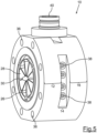
- the inflow and outflow sections can, for example, have connecting means for connecting the flow measuring device to the pipe (e.g. a pipeline), in particular in the form of a flange with screw holes.
- the pipe e.g. a pipeline
- the inflow section, the measuring section and the outflow section together form the flow space, i.e. the area of space in the measuring device through which the fluid flows.
- the transport direction is determined in particular by the shape of the measuring section, i.e. by the shape of the flow space in the measuring section (but possibly also together with the inflow and outflow sections).
- the transport direction is in particular the direction in which the fluid is transported and/or in which the fluid would flow if the flow measuring device did not have any flow deflection means.
- the measuring section or the entire flow space can be formed by a straight pipe.
- the transport direction is then the longitudinal direction of the pipe.
- the transport direction can accordingly be the direction in which the fluid mainly flows in the flow measuring device, for example to get from the inflow section to the outflow section.
- the transport direction could accordingly also be referred to as the main flow direction, i.e. as the flow direction that would exist without the flow deflection means.
- the flow deflection means give the fluid or the flow of the fluid a component that does not run along the transport direction, but at least partially at an angle to the transport direction.
- the angle between the transport direction and the deflected flow can be at least 25°, 30° or 40°.
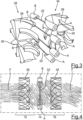
- the flow deflection means can, for example, have vanes arranged in the flow space that deflect the fluid sideways and thus introduce a type of rotation or swirl into the flow.
- the component of the flow that does not only run along the transport direction can then be measured using the ultrasound device arranged according to the invention.
- the deflected flow can describe an arc or a partial circle, particularly along the transport direction.
- a flow is the directed movement of a fluid.
- the ultrasound device comprises at least one ultrasound transmitter and one ultrasound receiver, which are arranged at opposite ends of one of the sound paths.
- units which combine ultrasound transmitters and ultrasound receivers i.e. so-called transducers, are arranged at opposite ends of a sound path.
- the ultrasound unit can accordingly comprise one or more pairs of transducers.
- the transducers make it easy to measure the transit time of ultrasonic waves through the sound path once in the forward direction and once in the reverse direction in order to determine a transit time difference, as will be explained in more detail later.
- the sound path is at least substantially perpendicular to the transport direction, so that two transducers belonging to a sound path are each arranged at the same location along the transport direction. Spacing the transducers along the transport direction is not necessary.
- several sound paths are formed, which are in particular parallel to one another and preferably lie in the same plane, with the transport direction forming a normal to this plane. An even more precise measurement result can be achieved by using several sound paths.
- the travel time through the sound path is shortened in one direction and the travel time is extended in the opposite direction.
- the actual measurement value of the travel time difference that is created in this way accumulates over the forward and backward signal of ultrasonic waves.
- the evaluation can be carried out with a single angle (e.g. determined experimentally), whereby the flow velocity and thus the flow rate can still be determined very precisely.
- the invention there are several sound paths parallel to one another. Multiple sound paths allow measurements to be taken at different positions in the cross-section of the measuring section. In addition, measurements can be carried out simultaneously using multiple sound paths. Both aspects allow the overall flow rate to be determined with greater accuracy. In particular, the accuracy increases with an increasing number of sound paths with the square root of the number of sound paths.
- a flow redirection means is provided, which is preferably arranged in the discharge section, wherein the The flow redirection means is designed to redirect the diverted flow (coming from the measuring section) so that the flow runs at least essentially parallel to the transport direction or is at least diverted in the direction of a flow parallel to the transport direction.
- the flow redirection means can therefore serve to ensure that a homogeneous and straight flow is present again after the outflow section. It goes without saying that the flow after the outflow section does not have to run parallel and straight in the mathematical sense. Small turbulences or small cross flows can also still be present.
Landscapes
- Physics & Mathematics (AREA)
- Fluid Mechanics (AREA)
- General Physics & Mathematics (AREA)
- Electromagnetism (AREA)
- Measuring Volume Flow (AREA)
Claims (15)
- Dispositif de mesure de débit (10) pour mesurer un paramètre, en particulier pour déterminer une quantité du débit d'un flux formé d'un fluide (F), le dispositif de mesure de débit (10) comprenant un espace d'écoulement (20) ayant une portion d'entrée (12) et une portion de sortie (16) ainsi qu'une portion de mesure (14) disposée entre la portion d'entrée (12) et la portion de sortie (16), la portion de mesure (14) définissant une direction de transport (24), au moins un dispositif à ultrasons (A, B) destiné à émettre et/ou à recevoir des ondes ultrasonores étant disposé dans la portion de mesure (14), et
comprenant un moyen de déviation de flux (26, 42, 44) disposé de préférence au moins dans la portion d'entrée (12), lequel est conçu pour dévier le flux de telle sorte que le flux dans la portion de mesure (14) s'écoule au moins localement en oblique par rapport à la direction de transport (24), caractérisé en ce que le dispositif à ultrasons (A, B) est conçu pour émettre les ondes ultrasonores à travers le fluide (F) sur plusieurs chemins sonores (22) au moins sensiblement perpendiculaires à la direction de transport (24) et/ou pour recevoir les ondes ultrasonores depuis le fluide (F) sur plusieurs chemins sonores (22) au moins sensiblement perpendiculaires à la direction de transport (24), sachant qu'il existe plusieurs chemins sonores (22) parallèles entre eux et que des transducteurs (A, B) sont disposés à des extrémités opposées des chemins sonores. - Dispositif de mesure de débit (10) selon la revendication 1,
dans lequel l'un au moins des chemins sonores (22) ou tous les chemins sonores (22) s'étend(ent) de manière excentrée dans la portion de mesure (14). - Dispositif de mesure de débit (10) selon la revendication 1 ou 2,
dans lequel sont prévus au moins deux chemins sonores (22) perpendiculaires entre eux. - Dispositif de mesure de débit (10) selon l'une des revendications précédentes,
dans lequel le moyen de déviation de flux (26, 42, 44) présente des surfaces de déviation (28) disposées dans l'espace d'écoulement (20). - Dispositif de mesure de débit (10) selon l'une des revendications précédentes,
dans lequel le moyen de déviation de flux comprend au moins un générateur de tourbillon (26) comportant une pluralité d'ailettes (28) qui s'étendent depuis une portion centrale de liaison (30) vers la paroi de l'espace d'écoulement (20). - Dispositif de mesure de débit (10) selon la revendication 5,
dans lequel les ailettes (28) partent de la même position et se terminent à la même position, vues le long de la direction de transport (24), les ailettes (28) ayant de préférence respectivement des géométries qui se correspondent. - Dispositif de mesure de débit (10) selon l'une des revendications précédentes,
dans lequel le moyen de déviation de flux (26, 42, 44) réduit, à sa position, la section transversale d'écoulement de moins de 15 %, de préférence de moins de 10 %. - Dispositif de mesure de débit (10) selon l'une des revendications précédentes,
dans lequel le moyen de déviation de flux (26, 42, 44) est conçu pour dévier le flux de telle sorte que le flux dévié soit axisymétrique autour d'un axe s'étendant le long de la direction de transport (24). - Dispositif de mesure de débit (10) selon l'une des revendications précédentes,
dans lequel est prévu un moyen de renvoi de flux (34), disposé de préférence dans la portion de sortie (16), qui est conçu pour dévier à nouveau le flux dévié, de telle sorte que le flux soit parallèle à la direction de transport (24). - Dispositif de mesure de débit (10) selon la revendication 9,
dans lequel le moyen de renvoi du flux (34) correspond au moyen de déviation de flux (26, 42, 44), le moyen de renvoi de flux (34) et le moyen de déviation de flux (26, 42, 44) étant de préférence des pièces identiques. - Dispositif de mesure de débit (10) selon l'une des revendications précédentes,
dans lequel le dispositif de mesure de débit (10) est symétrique au moins par rapport aux composants qui entrent en contact avec le fluide (F). - Dispositif de mesure de débit (10) selon l'une des revendications précédentes,
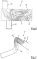
dans lequel le moyen de déviation de flux comprend au moins une conduite d'alimentation (42) qui débouche dans l'espace d'écoulement (20) de manière oblique ou transversale par rapport à la direction de transport (24) et qui permet d'introduire un fluide (F) dans l'espace d'écoulement (20). - Dispositif de mesure de débit (10) selon l'une des revendications précédentes,
dans lequel la portion d'entrée (12), la portion de mesure (14) et la portion de sortie (16) forment ensemble un tube (18), en particulier droit, et présentent ensemble une longueur inférieure à 1,5 fois, de préférence inférieure à 1,2 fois, le diamètre du tube. - Dispositif de mesure de débit (10) selon l'une des revendications précédentes,
dans lequel le dispositif de mesure de débit (10) comprend une unité d'évaluation qui est couplée au dispositif à ultrasons (A, B) et qui est conçue pour effectuer une mesure de la différence des temps de transit et pour déterminer le paramètre. - Procédé pour mesurer un paramètre, en particulier pour déterminer une quantité du débit d'un flux formé d'un fluide (F),le fluide (F) s'écoulant dans une direction de transport (24), etle flux étant dévié à l'aide d'un moyen de déviation de flux (26, 42, 44) de telle sorte que le flux dans une portion de mesure (14) s'écoule au moins localement en oblique par rapport à la direction de transport (24), caractérisé en ce quedes ondes ultrasonores sont émises à travers le fluide (F) sur plusieurs chemins sonores (22) au moins sensiblement perpendiculaires à la direction de transport (24) et/ou sont reçues depuis le fluide (F) sur plusieurs chemins sonores (22) au moins sensiblement perpendiculaires à la direction de transport (24), sachant qu'il existe plusieurs chemins sonores (22) parallèles entre eux et que des transducteurs (A, B) sont disposés à des extrémités opposées des chemins sonores.
Priority Applications (3)
| Application Number | Priority Date | Filing Date | Title |
|---|---|---|---|
| EP23161323.3A EP4428501B1 (fr) | 2023-03-10 | 2023-03-10 | Dispositif de mesure de débit |
| US18/600,346 US20240302194A1 (en) | 2023-03-10 | 2024-03-08 | Flow measurement apparatus |
| CN202410272699.0A CN118623960A (zh) | 2023-03-10 | 2024-03-11 | 测流设备 |
Applications Claiming Priority (1)
| Application Number | Priority Date | Filing Date | Title |
|---|---|---|---|
| EP23161323.3A EP4428501B1 (fr) | 2023-03-10 | 2023-03-10 | Dispositif de mesure de débit |
Publications (2)
| Publication Number | Publication Date |
|---|---|
| EP4428501A1 EP4428501A1 (fr) | 2024-09-11 |
| EP4428501B1 true EP4428501B1 (fr) | 2025-02-26 |
Family
ID=85571272
Family Applications (1)
| Application Number | Title | Priority Date | Filing Date |
|---|---|---|---|
| EP23161323.3A Active EP4428501B1 (fr) | 2023-03-10 | 2023-03-10 | Dispositif de mesure de débit |
Country Status (3)
| Country | Link |
|---|---|
| US (1) | US20240302194A1 (fr) |
| EP (1) | EP4428501B1 (fr) |
| CN (1) | CN118623960A (fr) |
Family Cites Families (11)
| Publication number | Priority date | Publication date | Assignee | Title |
|---|---|---|---|---|
| JP2567097B2 (ja) * | 1987-12-11 | 1996-12-25 | 株式会社東芝 | 流量測定装置 |
| GB2238615A (en) * | 1989-12-01 | 1991-06-05 | Ws Atkins Engineering Sciences | Swirl flowmeter for multiphase fluid streams |
| DE59611269D1 (de) * | 1996-02-16 | 2005-10-13 | Landis & Gyr Gmbh | Ultraschall-Messwertgeber zur Bestimmung der Durchflussmenge einer strömenden Flüssigkeit |
| EP1182431A4 (fr) * | 1999-03-17 | 2006-06-14 | Matsushita Electric Industrial Co Ltd | Debitmetre a ultrasons |
| CN101639371B (zh) * | 2009-09-09 | 2012-05-09 | 南京西奥仪表测控有限公司 | 可冗余测量的智控涡轮流量计 |
| EP2375224B1 (fr) * | 2010-03-18 | 2016-02-10 | SICK Engineering GmbH | Dispositif de mesure des ultrasons et procédé de mesure de la vitesse d'écoulement d'un liquide |
| CN102322906A (zh) * | 2011-09-08 | 2012-01-18 | 威海市天罡仪表有限公司 | 旋转式稳流器 |
| CN106768105B (zh) * | 2016-12-26 | 2019-12-31 | 威海市天罡仪表股份有限公司 | 采集切向速度测量流量的方法及装置 |
| GB201808918D0 (en) * | 2018-05-31 | 2018-07-18 | Sentec Ltd | Flow measurement improvement |
| US10845224B2 (en) * | 2018-12-03 | 2020-11-24 | Saudi Arabian Oil Company | Ultrasonic flow measurement for multiphase fluids using swirl blade section causing vortical flow for central gas flow region |
| WO2023274557A1 (fr) * | 2021-07-02 | 2023-01-05 | SONOTEC GmbH | Cellule de mesure à ultrasons et procédé de mesure du débit volumique d'un liquide dans un tube |
-
2023
- 2023-03-10 EP EP23161323.3A patent/EP4428501B1/fr active Active
-
2024
- 2024-03-08 US US18/600,346 patent/US20240302194A1/en active Pending
- 2024-03-11 CN CN202410272699.0A patent/CN118623960A/zh active Pending
Also Published As
| Publication number | Publication date |
|---|---|
| CN118623960A (zh) | 2024-09-10 |
| US20240302194A1 (en) | 2024-09-12 |
| EP4428501A1 (fr) | 2024-09-11 |
Similar Documents
| Publication | Publication Date | Title |
|---|---|---|
| EP2375224B1 (fr) | Dispositif de mesure des ultrasons et procédé de mesure de la vitesse d'écoulement d'un liquide | |
| DE69429994T2 (de) | Verfahren und vorrichtung zur bestimmung der eigenschaften einer fluidumströmung | |
| EP2607718B1 (fr) | Tranquilliseur de débit | |
| DE19509858A1 (de) | Strömungsgleichrichter für einen Turbinenlaufrad-Gaszähler | |
| EP3006903B1 (fr) | Débitmètre destiné à mesurer un paramètre d'un flux formé par un fluide | |
| DE102013105922A1 (de) | Ultraschall-Durchflussmessgerät | |
| EP2103911B1 (fr) | Mesure de l'écoulement à ultrasons | |
| EP2172657A2 (fr) | Guide d'écoulement pour un appareil de mesure du débit, notamment un appareil de mesure à ultrasons | |
| DE2212746B2 (de) | Stroemungsrichter | |
| DE102004053142A1 (de) | Flanschwirbeldurchflußmesser mit unitären zulaufenden Erweiterungsstücken | |
| EP3388794B1 (fr) | Dispositif de mesure du débit destiné à mesurer le débit d'un fluide | |
| EP3762686B1 (fr) | Débitmètre d'écoulement fluide | |
| EP3273205B1 (fr) | Procédé et système de débitmetre à ultrasons clamp-on et corps destiné à réaliser la mesure | |
| EP0715155B1 (fr) | Débitmètre à ultrason | |
| EP3403057B1 (fr) | Compteur de fluide à ultrasons et procédé de détermination de débit et/ou de volume d'un milieu en écoulement | |
| DE102010053261B4 (de) | Messkapsel zur Durchflussmessung | |
| EP2146189B1 (fr) | Mesure par ultra-sons de la vitesse d'écoulement | |
| EP4182703B1 (fr) | Débitmètre et procédé de mesure du débit d'un fluide | |
| DE19503714A1 (de) | Anordnung zur Bestimmung der Strömungsgeschwindigkeit eines Fluides in Rohren mit kreisförmigem Querschnitt mittels Ultraschall | |
| EP3599446A1 (fr) | Compteur à ultrasons | |
| EP4428501B1 (fr) | Dispositif de mesure de débit | |
| EP3748309B1 (fr) | Débitmètre à ultrasons, utilisation d'un débitmètre à ultrasons dans un organe d'arrêt et organe d'arrêt | |
| EP4356012A1 (fr) | Rectificateur d'écoulement | |
| DE102017009393B3 (de) | Einrichtung zur Steuerung des Verbrennungsprozesses in einer Kraftwerksfeuerungsanlage | |
| DE102020126021A1 (de) | Fluidmesseinrichtung |
Legal Events
| Date | Code | Title | Description |
|---|---|---|---|
| PUAI | Public reference made under article 153(3) epc to a published international application that has entered the european phase |
Free format text: ORIGINAL CODE: 0009012 |
|
| STAA | Information on the status of an ep patent application or granted ep patent |
Free format text: STATUS: REQUEST FOR EXAMINATION WAS MADE |
|
| 17P | Request for examination filed |
Effective date: 20240521 |
|
| AK | Designated contracting states |
Kind code of ref document: A1 Designated state(s): AL AT BE BG CH CY CZ DE DK EE ES FI FR GB GR HR HU IE IS IT LI LT LU LV MC ME MK MT NL NO PL PT RO RS SE SI SK SM TR |
|
| GRAP | Despatch of communication of intention to grant a patent |
Free format text: ORIGINAL CODE: EPIDOSNIGR1 |
|
| STAA | Information on the status of an ep patent application or granted ep patent |
Free format text: STATUS: GRANT OF PATENT IS INTENDED |
|
| INTG | Intention to grant announced |
Effective date: 20241001 |
|
| RBV | Designated contracting states (corrected) |
Designated state(s): AL AT BE BG CH CY CZ DE DK EE ES FI FR GB GR HR HU IE IS IT LI LT LU LV MC ME MK MT NL NO PL PT RO RS SE SI SK SM TR |
|
| GRAS | Grant fee paid |
Free format text: ORIGINAL CODE: EPIDOSNIGR3 |
|
| GRAA | (expected) grant |
Free format text: ORIGINAL CODE: 0009210 |
|
| STAA | Information on the status of an ep patent application or granted ep patent |
Free format text: STATUS: THE PATENT HAS BEEN GRANTED |
|
| AK | Designated contracting states |
Kind code of ref document: B1 Designated state(s): AL AT BE BG CH CY CZ DE DK EE ES FI FR GB GR HR HU IE IS IT LI LT LU LV MC ME MK MT NL NO PL PT RO RS SE SI SK SM TR |
|
| REG | Reference to a national code |
Ref country code: GB Ref legal event code: FG4D Free format text: NOT ENGLISH |
|
| REG | Reference to a national code |
Ref country code: CH Ref legal event code: EP |
|
| REG | Reference to a national code |
Ref country code: DE Ref legal event code: R081 Ref document number: 502023000599 Country of ref document: DE Owner name: ENDRESS+HAUSER SICK GMBH+CO. KG, DE Free format text: FORMER OWNER: ANMELDERANGABEN UNKLAR / UNVOLLSTAENDIG, 80297 MUENCHEN, DE Ref country code: DE Ref legal event code: R081 Ref document number: 502023000599 Country of ref document: DE Owner name: SICK ENGINEERING GMBH, DE Free format text: FORMER OWNER: ANMELDERANGABEN UNKLAR / UNVOLLSTAENDIG, 80297 MUENCHEN, DE |
|
| REG | Reference to a national code |
Ref country code: NL Ref legal event code: FP |
|
| REG | Reference to a national code |
Ref country code: DE Ref legal event code: R096 Ref document number: 502023000599 Country of ref document: DE |
|
| REG | Reference to a national code |
Ref country code: DE Ref legal event code: R081 Ref document number: 502023000599 Country of ref document: DE Owner name: ENDRESS+HAUSER SICK GMBH+CO. KG, DE Free format text: FORMER OWNER: SICK ENGINEERING GMBH, 01458 OTTENDORF-OKRILLA, DE |
|
| REG | Reference to a national code |
Ref country code: IE Ref legal event code: FG4D Free format text: LANGUAGE OF EP DOCUMENT: GERMAN |
|
| PG25 | Lapsed in a contracting state [announced via postgrant information from national office to epo] |
Ref country code: RS Free format text: LAPSE BECAUSE OF FAILURE TO SUBMIT A TRANSLATION OF THE DESCRIPTION OR TO PAY THE FEE WITHIN THE PRESCRIBED TIME-LIMIT Effective date: 20250526 |
|
| PG25 | Lapsed in a contracting state [announced via postgrant information from national office to epo] |
Ref country code: FI Free format text: LAPSE BECAUSE OF FAILURE TO SUBMIT A TRANSLATION OF THE DESCRIPTION OR TO PAY THE FEE WITHIN THE PRESCRIBED TIME-LIMIT Effective date: 20250226 |
|
| PG25 | Lapsed in a contracting state [announced via postgrant information from national office to epo] |
Ref country code: PL Free format text: LAPSE BECAUSE OF FAILURE TO SUBMIT A TRANSLATION OF THE DESCRIPTION OR TO PAY THE FEE WITHIN THE PRESCRIBED TIME-LIMIT Effective date: 20250226 |
|
| PG25 | Lapsed in a contracting state [announced via postgrant information from national office to epo] |
Ref country code: ES Free format text: LAPSE BECAUSE OF FAILURE TO SUBMIT A TRANSLATION OF THE DESCRIPTION OR TO PAY THE FEE WITHIN THE PRESCRIBED TIME-LIMIT Effective date: 20250226 |
|
| REG | Reference to a national code |
Ref country code: LT Ref legal event code: MG9D |
|
| PG25 | Lapsed in a contracting state [announced via postgrant information from national office to epo] |
Ref country code: IS Free format text: LAPSE BECAUSE OF FAILURE TO SUBMIT A TRANSLATION OF THE DESCRIPTION OR TO PAY THE FEE WITHIN THE PRESCRIBED TIME-LIMIT Effective date: 20250626 |
|
| PGFP | Annual fee paid to national office [announced via postgrant information from national office to epo] |
Ref country code: IT Payment date: 20250331 Year of fee payment: 3 |
|
| PG25 | Lapsed in a contracting state [announced via postgrant information from national office to epo] |
Ref country code: HR Free format text: LAPSE BECAUSE OF FAILURE TO SUBMIT A TRANSLATION OF THE DESCRIPTION OR TO PAY THE FEE WITHIN THE PRESCRIBED TIME-LIMIT Effective date: 20250226 |
|
| PG25 | Lapsed in a contracting state [announced via postgrant information from national office to epo] |
Ref country code: LV Free format text: LAPSE BECAUSE OF FAILURE TO SUBMIT A TRANSLATION OF THE DESCRIPTION OR TO PAY THE FEE WITHIN THE PRESCRIBED TIME-LIMIT Effective date: 20250226 Ref country code: PT Free format text: LAPSE BECAUSE OF FAILURE TO SUBMIT A TRANSLATION OF THE DESCRIPTION OR TO PAY THE FEE WITHIN THE PRESCRIBED TIME-LIMIT Effective date: 20250626 |
|
| PG25 | Lapsed in a contracting state [announced via postgrant information from national office to epo] |
Ref country code: BG Free format text: LAPSE BECAUSE OF FAILURE TO SUBMIT A TRANSLATION OF THE DESCRIPTION OR TO PAY THE FEE WITHIN THE PRESCRIBED TIME-LIMIT Effective date: 20250226 Ref country code: GR Free format text: LAPSE BECAUSE OF FAILURE TO SUBMIT A TRANSLATION OF THE DESCRIPTION OR TO PAY THE FEE WITHIN THE PRESCRIBED TIME-LIMIT Effective date: 20250527 |
|
| PG25 | Lapsed in a contracting state [announced via postgrant information from national office to epo] |
Ref country code: SE Free format text: LAPSE BECAUSE OF FAILURE TO SUBMIT A TRANSLATION OF THE DESCRIPTION OR TO PAY THE FEE WITHIN THE PRESCRIBED TIME-LIMIT Effective date: 20250226 |
|
| PG25 | Lapsed in a contracting state [announced via postgrant information from national office to epo] |
Ref country code: SM Free format text: LAPSE BECAUSE OF FAILURE TO SUBMIT A TRANSLATION OF THE DESCRIPTION OR TO PAY THE FEE WITHIN THE PRESCRIBED TIME-LIMIT Effective date: 20250226 |
|
| PG25 | Lapsed in a contracting state [announced via postgrant information from national office to epo] |
Ref country code: DK Free format text: LAPSE BECAUSE OF FAILURE TO SUBMIT A TRANSLATION OF THE DESCRIPTION OR TO PAY THE FEE WITHIN THE PRESCRIBED TIME-LIMIT Effective date: 20250226 |
|
| PG25 | Lapsed in a contracting state [announced via postgrant information from national office to epo] |
Ref country code: CZ Free format text: LAPSE BECAUSE OF FAILURE TO SUBMIT A TRANSLATION OF THE DESCRIPTION OR TO PAY THE FEE WITHIN THE PRESCRIBED TIME-LIMIT Effective date: 20250226 Ref country code: EE Free format text: LAPSE BECAUSE OF FAILURE TO SUBMIT A TRANSLATION OF THE DESCRIPTION OR TO PAY THE FEE WITHIN THE PRESCRIBED TIME-LIMIT Effective date: 20250226 |
|
| PG25 | Lapsed in a contracting state [announced via postgrant information from national office to epo] |
Ref country code: RO Free format text: LAPSE BECAUSE OF FAILURE TO SUBMIT A TRANSLATION OF THE DESCRIPTION OR TO PAY THE FEE WITHIN THE PRESCRIBED TIME-LIMIT Effective date: 20250226 |
|
| PG25 | Lapsed in a contracting state [announced via postgrant information from national office to epo] |
Ref country code: SK Free format text: LAPSE BECAUSE OF FAILURE TO SUBMIT A TRANSLATION OF THE DESCRIPTION OR TO PAY THE FEE WITHIN THE PRESCRIBED TIME-LIMIT Effective date: 20250226 |
|
| PG25 | Lapsed in a contracting state [announced via postgrant information from national office to epo] |
Ref country code: LU Free format text: LAPSE BECAUSE OF NON-PAYMENT OF DUE FEES Effective date: 20250310 |
|
| REG | Reference to a national code |
Ref country code: DE Ref legal event code: R097 Ref document number: 502023000599 Country of ref document: DE |
|
| REG | Reference to a national code |
Ref country code: BE Ref legal event code: MM Effective date: 20250331 |
|
| PG25 | Lapsed in a contracting state [announced via postgrant information from national office to epo] |
Ref country code: MC Free format text: LAPSE BECAUSE OF FAILURE TO SUBMIT A TRANSLATION OF THE DESCRIPTION OR TO PAY THE FEE WITHIN THE PRESCRIBED TIME-LIMIT Effective date: 20250226 |
|
| PLBE | No opposition filed within time limit |
Free format text: ORIGINAL CODE: 0009261 |
|
| STAA | Information on the status of an ep patent application or granted ep patent |
Free format text: STATUS: NO OPPOSITION FILED WITHIN TIME LIMIT |
|
| PG25 | Lapsed in a contracting state [announced via postgrant information from national office to epo] |
Ref country code: BE Free format text: LAPSE BECAUSE OF NON-PAYMENT OF DUE FEES Effective date: 20250331 |
|
| PG25 | Lapsed in a contracting state [announced via postgrant information from national office to epo] |
Ref country code: IE Free format text: LAPSE BECAUSE OF NON-PAYMENT OF DUE FEES Effective date: 20250310 |
|
| 26N | No opposition filed |
Effective date: 20251127 |
|
| REG | Reference to a national code |
Ref country code: NL Ref legal event code: HC Owner name: ENDRESS+HAUSER SICK GMBH+CO. KG; DE Free format text: DETAILS ASSIGNMENT: CHANGE OF OWNER(S), CHANGE OF OWNER(S) NAME; FORMER OWNER NAME: SICK ENGINEERING GMBH Effective date: 20260327 |
|
| PGFP | Annual fee paid to national office [announced via postgrant information from national office to epo] |
Ref country code: NO Payment date: 20260320 Year of fee payment: 4 Ref country code: DE Payment date: 20260320 Year of fee payment: 4 |
|
| PGFP | Annual fee paid to national office [announced via postgrant information from national office to epo] |
Ref country code: AT Payment date: 20260301 Year of fee payment: 4 |
|
| PGFP | Annual fee paid to national office [announced via postgrant information from national office to epo] |
Ref country code: NL Payment date: 20260323 Year of fee payment: 4 |
|
| PGFP | Annual fee paid to national office [announced via postgrant information from national office to epo] |
Ref country code: FR Payment date: 20260325 Year of fee payment: 4 |