EP4428505A1 - Appareil et procédé - Google Patents
Appareil et procédé Download PDFInfo
- Publication number
- EP4428505A1 EP4428505A1 EP23275039.8A EP23275039A EP4428505A1 EP 4428505 A1 EP4428505 A1 EP 4428505A1 EP 23275039 A EP23275039 A EP 23275039A EP 4428505 A1 EP4428505 A1 EP 4428505A1
- Authority
- EP
- European Patent Office
- Prior art keywords
- optical
- das
- multiplexer
- section
- circuit
- Prior art date
- Legal status (The legal status is an assumption and is not a legal conclusion. Google has not performed a legal analysis and makes no representation as to the accuracy of the status listed.)
- Pending
Links
- 238000000034 method Methods 0.000 title claims description 13
- 230000003287 optical effect Effects 0.000 claims abstract description 553
- 239000013307 optical fiber Substances 0.000 claims abstract description 131
- 238000004891 communication Methods 0.000 claims abstract description 44
- 238000012544 monitoring process Methods 0.000 claims description 10
- 238000011144 upstream manufacturing Methods 0.000 claims description 9
- 239000000835 fiber Substances 0.000 description 20
- 230000003321 amplification Effects 0.000 description 6
- 238000003199 nucleic acid amplification method Methods 0.000 description 6
- 230000005540 biological transmission Effects 0.000 description 4
- 238000001514 detection method Methods 0.000 description 4
- 238000012546 transfer Methods 0.000 description 4
- 238000013461 design Methods 0.000 description 3
- 238000000253 optical time-domain reflectometry Methods 0.000 description 3
- 230000011664 signaling Effects 0.000 description 3
- 229910052691 Erbium Inorganic materials 0.000 description 2
- 238000013459 approach Methods 0.000 description 2
- 230000002457 bidirectional effect Effects 0.000 description 2
- 230000000694 effects Effects 0.000 description 2
- UYAHIZSMUZPPFV-UHFFFAOYSA-N erbium Chemical compound [Er] UYAHIZSMUZPPFV-UHFFFAOYSA-N 0.000 description 2
- 239000000463 material Substances 0.000 description 2
- 230000007246 mechanism Effects 0.000 description 2
- 238000005192 partition Methods 0.000 description 2
- 238000011084 recovery Methods 0.000 description 2
- 238000000926 separation method Methods 0.000 description 2
- 238000005516 engineering process Methods 0.000 description 1
- 230000007717 exclusion Effects 0.000 description 1
- 238000000605 extraction Methods 0.000 description 1
- 239000012535 impurity Substances 0.000 description 1
- 230000002452 interceptive effect Effects 0.000 description 1
- 230000004807 localization Effects 0.000 description 1
- 230000000644 propagated effect Effects 0.000 description 1
- 230000035945 sensitivity Effects 0.000 description 1
Images



Classifications
-
- H—ELECTRICITY
- H04—ELECTRIC COMMUNICATION TECHNIQUE
- H04B—TRANSMISSION
- H04B10/00—Transmission systems employing electromagnetic waves other than radio-waves, e.g. infrared, visible or ultraviolet light, or employing corpuscular radiation, e.g. quantum communication
- H04B10/07—Arrangements for monitoring or testing transmission systems; Arrangements for fault measurement of transmission systems
- H04B10/075—Arrangements for monitoring or testing transmission systems; Arrangements for fault measurement of transmission systems using an in-service signal
- H04B10/077—Arrangements for monitoring or testing transmission systems; Arrangements for fault measurement of transmission systems using an in-service signal using a supervisory or additional signal
-
- G—PHYSICS
- G01—MEASURING; TESTING
- G01H—MEASUREMENT OF MECHANICAL VIBRATIONS OR ULTRASONIC, SONIC OR INFRASONIC WAVES
- G01H9/00—Measuring mechanical vibrations or ultrasonic, sonic or infrasonic waves by using radiation-sensitive means, e.g. optical means
- G01H9/004—Measuring mechanical vibrations or ultrasonic, sonic or infrasonic waves by using radiation-sensitive means, e.g. optical means using fibre optic sensors
Definitions
- the present invention relates to optical cables.
- undersea fibre optic cables also known as optical fibre cables.
- 2017 2017 was estimated that 97% of all internet and telecommunication traffic moved through undersea fibre optic cables.
- an optical communication system comprising:
- an optical circuit comprising an optical isolator and a distributed acoustic sensing, DAS, circuit comprising a DAS optical transmitter and/or a DAS optical receiver and a DAS multiplexer / de-multiplexer and/or a DAS circulator.
- a method of monitoring an optical fibre cable assembly comprising:
- an optical communication system comprising:
- distributed acoustic sensing is provided along the along the first section or the second section of the optical fibre cable.
- distributed acoustic sensing may be provided along the full length (i.e. all the sections) of the optical fibre cable, by including DAS circuits for every section, for example.
- monitoring, by distributed acoustic sensing may be provided for amplified optical fibre cables used for international telecommunications.
- conventional DAS solutions for distributed sensing in optical fibre cables depend on the detection of backscattered light which is blocked or corrupted by components in the optical fibre cables, such as optical isolators.
- the magnitude of the DAS signals diminishes due to attenuation and other loss mechanisms, limiting the effective usable range of conventional DAS solutions to about 50 km from the terminal.
- optical communication systems also known as optical telecommunication systems or optical network systems
- optical network systems optical network systems
- the optical communication system comprises the optical transmitter and the optical receiver mutually optically coupled via (i.e. by) the optical fibre cable assembly.
- an optical communication system uses an optical transmitter to encode a message into an optical signal and transmit the optical signal, a channel (e.g. an optical fibre cable) to carry the optical signal and an optical receiver to receive and decode the message from the received optical signal.
- a channel e.g. an optical fibre cable
- the optical transmitter is configured to transmit the optical signal to the optical receiver via (i.e. though) the optical fibre cable assembly.
- the optical receiver is configured to receive the optical signal transmitted by the optical transmitter via the optical fibre cable assembly.
- the optical transmitter and the optical receiver are unidirectionally mutually optically coupled via the optical fibre cable assembly.
- the optical transmitter and the optical receiver are bidirectionally mutually optically coupled via the optical fibre cable assembly. It should be understood that the optical transmitter and the optical receiver may be bidirectionally mutually optically coupled via the optical fibre cable assembly even though the optical fibre cable assembly includes the first optical isolator, as described below in more detail.
- a wavelength of the optical signal is in the S-band (i.e. in a wavelength range from 1460 nm to 1530 nm), C-band (i.e. in a wavelength range from 1530 nm to 1565 nm) or L-band (i.e. in a wavelength range from 1565 nm to 1625 nm).
- the optical fibre cable assembly comprises the optical fibre cable and the set of optical circuits (also known as nodes). Suitable optical fibre cables are known.
- the set of optical circuits is disposed to section (i.e. partition, divide) the optical fibre cable into the series of optical fibre cable sections (i.e. partitions, divisions), including the first section and the second section. It should be understood that the first section and the second section are disposed in series (i.e. serially disposed, arranged in tandem, adjacent end to end c.f. disposed in parallel). In one example, the first section and the second section are mutually optically coupled via the first optical circuit. That is, the first section and the second section are in optical communication via the first optical circuit.
- the series of optical fibre cable sections are mutually optically coupled via the set of optical circuits.
- the set of optical circuits includes M optical circuits, including the first optical circuit, wherein M is a natural number greater than or equal to 1, for example 1, 2, 3, 4, 5, 6, 7, 8, 9, 10, 20, 30, 40, 50, 60, 70, 80, 90, 100 or more, disposed to section the optical fibre cable into the series of N optical fibre cable sections, including the first section and the second section, wherein N is a natural number greater than or equal to 2, for example 2, 3, 4, 5, 6, 7, 8, 9, 10, 20, 30, 40, 50, 60, 70, 80, 90, 100 or more.
- N is greater than M.
- N M + 1.
- M is in a range from 1 to 1,000, preferably in a range from 2 to 750, more preferably in a range from 3 to 500.
- N is in a range from 2 to 1,001, preferably in a range from 3 to 751, more preferably in a range from 4 to 501.
- the first section has a length in a range from 10 km to 100 km, preferably in a range from 25 km to 75 km, more preferably in a range from 40 km to 60 km, for example 50 km.
- the second section (more generally each section) may be as described with respect to the first section.
- the set of optical circuits includes the first optical circuit comprising the first optical isolator (also known as an optical diode).
- the first optical isolator allows transmission of optical signals in only one direction (i.e. unidirectionally).
- an optical isolator is used to prevent unwanted feedback, such as back reflections or signals that may occur after the optical isolator, into an optical oscillator, such as a laser cavity. Back reflections can damage a laser source or cause the laser source to mode hop, amplitude modulate, or frequency shift, for example. Back reflections can additionally and/or alternatively provide amplification wavelength sensitivity in the amplifiers or even cause them to oscillate (turn them into lasers), preventing their amplifying signals correctly.
- optical isolator are passive magneto-optic devices. That is, the first optical isolator would preclude use of conventional DAS, since the first optical isolator would otherwise prevent backscattering of the DAS optical signal, that is required for DAS.
- the optical communication system comprises the set of distributed acoustic sensing, DAS, circuits, including the first DAS circuit, wherein the first DAS circuit comprises the first DAS optical transmitter, the first DAS multiplexer / de-multiplexer and/or a first DAS circulator and the first DAS optical receiver.
- Suitable DAS optical transmitters, DAS multiplexer / de-multiplexers, DAS circulators and DAS optical receivers are known.
- the first DAS multiplexer / de-multiplexer comprises and/or is a dichroic filter, an arrayed waveguide grating (AWGN), a chromatic prism or a simple optical filter arrangement.
- AWGN arrayed waveguide grating
- Other DAS multiplexer / de-multiplexers are known.
- the first DAS optical transmitter is configured to transmit the first DAS optical signal to the first DAS optical receiver via (i.e. through) the first section or the second section of the optical fibre cable and via the first DAS multiplexer / de-multiplexer and/or the first DAS circulator.
- the first DAS optical signal is transmitted by the first DAS optical transmitter through the first section or the second section of the optical fibre (i.e. upstream or downstream of the first optical circuit) to the first DAS optical receiver, for monitoring of the respective section using DAS.
- respective wavelengths of the first optical signal and of the first DAS optical signal are mutually different. In this way, the first optical signal and the first DAS optical signal may be mutually discriminated.
- a wavelength of the first optical signal is inside the S-band, the C-band or the L-band and a wavelength of the first DAS optical signal is outside the S-band, the C-band or the L-band, respectively, for example 1480 nm, 1510 nm or 1610 nm.
- respective polarisations of the first optical signal and of the first DAS optical signal are mutually different, for example mutually orthogonal. In this way, the first optical signal and the first DAS optical signal may be mutually discriminated.
- the first transmitter and the first DAS transmitter are configured to transmit the first optical signal and the first DAS optical signal asynchronously, for example at different times such as during scheduled gaps in data transfer using the optical signal.
- the first DAS optical transmitter is configured to transmit the first DAS optical signal to the first DAS optical receiver unidirectionally via the first section or the second section of the optical fibre cable and via the first DAS multiplexer / de-multiplexer and/or the first DAS circulator.
- the first section or the second section of the optical fibre may be monitored unidirectionally by DAS.
- the DAS optical transmitter may be disposed with the optical transmitter and the DAS optical receiver may be disposed with and/or included in the first optical circuit or vice versa.
- the DAS optical transmitter may be disposed with the optical receiver and the DAS optical receiver may be disposed with and/or included in the first optical circuit or vice versa.
- the DAS optical transmitter may be disposed with and/or included in the first optical circuit and the DAS optical receiver may be disposed with and/or included in a second optical circuit or vice versa.
- the first DAS optical transmitter is configured to transmit the first DAS optical signal to the first DAS optical receiver bidirectionally via the first section or the second section of the optical fibre cable and via the first DAS multiplexer / de-multiplexer and/or the first DAS circulator.
- the first DAS optical transmitter and the first DAS optical receiver may be disposed with the optical transmitter, the optical transmitter or with and/or included in the first optical circuit. In this way, the first section or the second section of the optical fibre may be monitored bidirectionally by DAS.
- the first DAS circuit comprises a first retroreflector (also known as a retroflector or a cataphote), configured to reflect the first DAS optical signal, transmitted by the first DAS optical transmitter via (i.e. through) the first section or the second section of the optical fibre cable, to the first DAS optical receiver via the first section or the second section of the optical fibre cable.
- a first retroreflector also known as a retroflector or a cataphote
- the first DAS optical transmitter and the first DAS optical receiver may be disposed with the optical transmitter or with the optical transmitter and the first retroflector disposed with and/or included in the first optical circuit or vice versa.
- the first DAS optical transmitter and the first DAS optical receiver may be disposed with and/or included in the first optical circuit and the first retroflector disposed with and/or included in a second optical circuit or vice versa.
- the first section or the second section of the optical fibre may be monitored bidirectionally by DAS.
- the first optical circuit comprises the first DAS multiplexer / de-multiplexer and/or the first DAS circulator.
- the first DAS multiplexer / de-multiplexer and/or the first DAS circulator is comprised in the first optical circuit, between the first section and the second section of the optical cable.
- the first DAS multiplexer / de-multiplexer comprises and/or is a wavelength-division multiplexer / de-multiplexer. Suitable wavelength-division multiplexers / de-multiplexers are known.
- the first DAS multiplexer / de-multiplexer comprises and/or is a polarization-division multiplexer / de-multiplexer. Suitable polarization-division multiplexers / de-multiplexers are known.
- the first DAS multiplexer / de-multiplexer comprises and/or is a time-division multiplexer / de-multiplexer. Suitable time-division multiplexers / de-multiplexers are known.
- the first optical circuit comprises the first DAS optical transmitter and/or the first DAS optical receiver.
- the first DAS optical transmitter and/or the first DAS optical receiver is comprised in the first optical circuit, between the first section and the second section of the optical cable.
- the first optical circuit comprises a first DAS retroreflector.
- the first DAS retroreflector is comprised in the first optical circuit, between the first section and the second section of the optical cable.
- the first optical circuit comprises a first optical amplifier. Suitable optical amplifiers are known.
- the first optical isolator is disposed (i.e. arranged or used) to protect the first optical amplifier (such as upstream or downstream thereof appropriately), as understood by the skilled person.
- the first optical circuit comprises a first multiplexer / de-multiplexer disposed upstream or downstream of the first optical isolator, for example for multiplexing / de-multiplexing the first optical signal for optical amplification by a first optical amplifier.
- the first multiplexer / de-multiplexer comprises and/or is a dichroic filter, an arrayed waveguide grating (AWGN), a chromatic prism or a simple optical filter arrangement.
- AWGN arrayed waveguide grating
- Other multiplexer / de-multiplexers are known.
- the first DAS optical transmitter is configured to transmit the first DAS optical signal, for example only the first DAS optical signal (i.e. excluding the first optical signal), to the first DAS optical receiver via the first section or the second section of the optical fibre cable, via the first multiplexer / de-multiplexer and via the first DAS multiplexer / de-multiplexer and/or the first DAS circulator.
- the first DAS optical signal may be transmitted through the first multiplexer / de-multiplexer and subsequently through the first DAS multiplexer / de-multiplexer and/or the first DAS circulator to the first DAS receiver.
- the first DAS optical signal may be transmitted through the first multiplexer / de-multiplexer and subsequently through the first DAS multiplexer / de-multiplexer and/or the first DAS circulator to a first DAS retroreflector and then back through the first DAS multiplexer / de-multiplexer and subsequently back through the first multiplexer / de-multiplexer to the first DAS receiver.
- the first optical circuit comprises a first supervisory circuit or part thereof. Suitable supervisory circuits are known.
- the first supervisory circuit comprises a first supervisory optical transmitter and/or a first supervisory optical receiver, wherein the first supervisory optical transmitter is configured to transmit a first supervisory optical signal to the first supervisory optical receiver via the first section or the second section and via the first multiplexer / de-multiplexer and optionally, via the first DAS multiplexer / de-multiplexer.
- supervisory optical signals may be communicated via the optical fibre cable assembly, as understood by the skilled person.
- respective wavelengths of the first DAS optical signal and of the first supervisory optical signal are mutually different.
- the first DAS optical signal and the first supervisory optical signal may be mutually discriminated.
- the first supervisory transmitter and the first DAS transmitter are configured to transmit the first supervisory signal and the first DAS optical signal asynchronously, for example at different times such as during scheduled gaps in the first supervisory optical signal.
- respective wavelengths of the first optical signal and of the first supervisory optical signal are mutually different. In this way, the first optical signal and the first supervisory optical signal may be mutually discriminated.
- a wavelength of the first optical signal is inside the S-band, the C-band or the L-band and a wavelength of the first supervisory signal is outside the S-band, the C-band or the L-band, respectively, for example 1480 nm, 1510 nm or 1610 nm.
- the first DAS multiplexer / de-multiplexer and/or the first DAS circulator is disposed upstream (for example, for the first section) or downstream (for example, for the second section) of the first supervisory circuit or part thereof.
- the first DAS multiplexer / de-multiplexer is disposed between the first multiplexer / de-multiplexer and the first supervisory receiver.
- the first de-multiplexer separates the communications channels (i.e. demultiplexes the first optical signal) and passes the first DAS optical signal and the first the first supervisory optical signal in the same direction while the first DAS de-multiplexer separates the first DAS optical signal from the first supervisory signal, which passes through the first DAS de-multiplexer while the first DAS optical signal is directed to the first DAS receiver or the first DAS retroreflector.
- the set of DAS circuits includes a second DAS circuit, wherein the second DAS circuit comprises a second DAS optical transmitter, a second DAS multiplexer / de-multiplexer and/or a second DAS circulator and a second DAS optical receiver;
- the second DAS circuit may be as described with respect to the first DAS circuit mutatis mutandis.
- Each DAS circuit may be as described with respect to the first DAS circuit mutatis mutandis.
- respective wavelengths of the first DAS optical signal and of the second DAS optical signal are mutually different. In this way, the first DAS optical signal and the second DAS optical signal may be mutually discriminated.
- an optical circuit comprising an optical isolator and a distributed acoustic sensing, DAS, circuit comprising a DAS optical transmitter and/or a DAS optical receiver and a DAS multiplexer / de-multiplexer and/or a DAS circulator.
- the optical isolator, the DAS circuit, the DAS optical transmitter, the DAS optical receiver, the DAS multiplexer / de-multiplexer and/or the DAS circulator may be as described with respect to the first aspect mutatis mutandis.
- the optical circuit comprises an optical amplifier, a multiplexer / de-multiplexer and/or a supervisory circuit or part thereof.
- the optical amplifier, the multiplexer / de-multiplexer and/or the supervisory circuit mutatis mutandis.
- a method of monitoring an optical fibre cable assembly comprising:
- the term “comprising” or “comprises” means including the component(s) specified but not to the exclusion of the presence of other components.
- the term “consisting essentially of” or “consists essentially of” means including the components specified but excluding other components except for materials present as impurities, unavoidable materials present as a result of processes used to provide the components, and components added for a purpose other than achieving the technical effect of the invention, such as colourants, and the like.
- Figure 1 is a schematic of a nominal long-range wavelength division multiplexed fibre optic cabled link. It incorporates a number of channels, each with different wavelengths and modulated with its own data stream. These are multiplexed together and launched into the fibre.
- the wavelengths are typically between 1525nm and 1565nm.
- the range is extended to include wavelengths from typically 1565nm and 1625nm.
- Each wavelength channel loses power at it travels along the fibre due to physical scattering and loss mechanisms in the fibre cable. For short links, this loss may be acceptable and enough power will be received at the far end to enable the recovery of the modulated signal.
- optical amplifiers are placed at intervals along the fibre to maintain the optical power. These intervals are typically no greater than 100km.
- the wavelengths are de-multiplexed and the signal detected.
- each cable may contain multiple fibres and amplifiers to increase the overall capacity of any link.
- a conventional optical communication system 1 comprises: an optical transmitter 11 and an optical receiver 12 mutually optically coupled via an optical fibre cable assembly 13 comprising an optical fibre cable 131 and a set of optical circuits 132, including a first optical circuit 132A comprising a first optical isolator 132A1 (not shown), wherein the optical transmitter 11 is configured to transmit an optical signal S to the optical receiver 12 via the optical fibre cable assembly 13, wherein the optical receiver 12 is configured to receive the optical signal S transmitted by the optical transmitter 11 via the optical fibre cable assembly 13 and wherein the set of optical circuits 132 is disposed to section the optical fibre cable 131 into a series of optical fibre cable sections 1311, including a first section 1311A and a second section 1311B.
- the optical transmitter 11 and the optical receiver 12 are unidirectionally mutually optically coupled via the optical fibre cable assembly 13.
- a wavelength of the optical signal S is in the S-band (i.e. in a wavelength range from 1460 nm to 1530 nm), C-band (i.e. in a wavelength range from 1530 nm to 1565 nm) or L-band (i.e. in a wavelength range from 1565 nm to 1625 nm).
- the first section 1311A and the second section 1311B are mutually optically coupled via the first optical circuit 132A.
- the first optical circuit 132A comprises a first optical amplifier 132A2 (not shown).
- the first optical isolator 132A1 is disposed to protect the first optical amplifier 132A2.
- N M + 1.
- Figure 2 is a schematic for the design for a simple amplifier 232A2, such as the first optical amplifier 132A2, as described previously. It will be appreciated that more complicated amplifier designs including those with a break in the middle to insert optical components exist. Architectures with separate C-band and L-band amplification and those allowing bidirectional transmission are envisaged. Some of these are described and illustrated in [1] for example.
- the signal S is received from the optical fibre cable fibre 231.
- a coupler C is used to tap off a small proportion of the energy so that the gain of the amplifier can be monitored.
- the signal next passes through an optical isolator which allows light to pass forward but not backward. This is needed so that the amplifier cannot oscillate due to stray reflections and to improve the noise figure of the amplifier and thus the overall system performance.
- the isolators block any signal reflected after them, and therefore prevent DAS from operating through an amplifier.
- the light passes into the active fibre (typically doped with erbium to provide gain) to which is coupled the pump laser light to activate the gain.
- the pump lasers are typically high-power lasers at 980nm or 1480nm (for erbium-based amplifiers).
- the pump laser can propagate forward (which is preferred for low noise), or backward (which is preferred for high output power). After passing through a backward pump laser coupler, and another isolator, a small proportion of the light is coupled out for the gain calculation. The signal(s) then pass on to the next section of transmission fibre.
- a conventional first optical circuit 232A of a conventional optical communication system 2, comprises a first optical isolator 232A1 (i.e. the isolator) and a first optical amplifier 232A2 (i.e. the pump laser).
- the first optical isolator 232A1 is disposed to protect the first optical amplifier 232A2.
- a conventional second optical circuit 232B comprises a second optical isolator 232B1 and a second optical amplifier 232B2.
- the second optical isolator 232B1 is disposed to protect the first optical amplifier 232B2.
- Control and monitoring of the amplifiers is desirable, and this is typically provided on a separate (supervisory) wavelength that is only allowed to propagate between neighbouring amplifiers.
- the optical structure of the amplifier allowing this is given in Figure 3 .
- the architecture i.e. optical circuits 232A, 232B
- the architecture is represented by the triangle 332 in Figure 3 for a conventional optical communication system 3.
- multiplexers or de-multiplexers 432A, 432B are provided. These could, for example, be dichroic filters, which reflect some wavelengths and transmit others.
- the supervisory wavelength sS of a first supervisory circuit or part thereof 332A4 is transmitted and the communications wavelength S are reflected by the dichroic mirror 432A.
- the opposite configuration can provide the same function.
- the supervisory wavelength sS transmitted at the previous amplifier is detected and its signals received e.g. to configure the amplifier or to pass on to later amplifiers.
- a modulated supervisory wavelength is transmitted to the next amplifier to provide information about the amplifier or to pass on information from earlier in the chain.
- the communications channels may have wavelengths in C-band (1526 to 1565nm) and/or L-band (1565 to 1625nm).
- the supervisory wavelength is typically outside this band to enable its separation, and could be for example 1480nm, 1510nm, or 1610nm.
- More complex amplifier structures can use a similar approach to drop and add this wavelength as disclosed in [1].
- This invention provides for an architecture that allows for the provision of OTDR and DAS signals through the amplifiers.
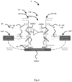
- An embodiment of this is shown schematically in Figure 4 .
- the inventive step here is provide an additional multiplexer / de-multiplexer, for example in the section between the first de-multiplexer and the supervisory channel detector.
- This separates out the DAS channel which could for example be any of the wavelengths 1480 nm, 1510 nm, or 1610 nm, or at another wavelength that is not used for the supervisory channel, or another wavelength which would otherwise transmit data.
- the first de-multiplexer separates the communications channels and passes the DAS channel in the same direction as the supervisory channel.
- the second stage separates the DAS and supervisory channels.
- an optical communication system 4 is generally as described with respect to the optical communication system 1 of Figure 1 , the first optical circuit 232A of Figure 2 and the first supervisory circuit 332A4 of Figure 3 .
- the optical communication system 4 comprises a set of distributed acoustic sensing, DAS, circuits 44, as described below.
- the optical communication system 4 comprising:
- the optical transmitter 41 and the optical receiver 42 are unidirectionally mutually optically coupled via the optical fibre cable assembly 43.
- a wavelength of the optical signal S is in the S-band (i.e. in a wavelength range from 1460 nm to 1530 nm), C-band (i.e. in a wavelength range from 1530 nm to 1565 nm) or L-band (i.e. in a wavelength range from 1565 nm to 1625 nm).
- the first section 4311A and the second section 4311B are mutually optically coupled via the first optical circuit 432A.
- the first DAS multiplexer / de-multiplexer 44A2 comprises and/or is a dichroic filter.
- respective wavelengths of the first optical signal S and of the first DAS optical signal s1 are mutually different.
- the first DAS optical transmitter 44A1 is configured to transmit the first DAS optical signal s1 to the first DAS optical receiver 44A3 bidirectionally via the first section 4311A of the optical fibre cable 431 and via the first DAS multiplexer / de-multiplexer 44A2.
- the first DAS circuit 44A comprises a first retroreflector 44A4 (not shown), configured to reflect the first DAS optical signal s1, transmitted by the first DAS optical transmitter 44A1 via the first section 4311A of the optical fibre cable, to the first DAS optical receiver 44A3 via the first section 4311A of the optical fibre cable.
- the first DAS optical transmitter 44A1 and the first DAS optical receiver 44A3 may be disposed with the optical transmitter 41 or with the optical transmitter 41 and the first retroflector disposed with and/or included in the first optical circuit 432A or vice versa.
- the first DAS optical transmitter 44A1 and the first DAS optical receiver 44A3 may be disposed with and/or included in the first optical circuit 432A and the first retroflector disposed with and/or included in a second optical circuit or vice versa.
- the first optical circuit 432A comprises the first DAS multiplexer / de-multiplexer 44A2.
- the first DAS multiplexer / de-multiplexer 44A2 comprises and/or is a wavelength-division multiplexer / de-multiplexer.
- the first optical circuit 432A comprises the first DAS optical transmitter 44A1 and/or the first DAS optical receiver 44A3.
- the first optical circuit 432A comprises the first DAS retroreflector 44A4.
- the first optical circuit 432A comprises a first optical amplifier 432A2 (not shown).
- the first optical isolator 432A1 is disposed to protect the first optical amplifier 432A2.
- the first optical circuit 432A comprises a first multiplexer / de-multiplexer 432A3 disposed upstream of the first optical isolator 432A1, for example for multiplexing / de-multiplexing the first optical signal S for optical amplification by a first optical amplifier.
- the first multiplexer / de-multiplexer 432A3 comprises and/or is a dichroic filter, an arrayed waveguide grating (AWGN), a chromatic prism or a simple optical filter arrangement.
- AWGN arrayed waveguide grating
- Other multiplexer / de-multiplexers are known.
- the first DAS optical transmitter 44A1 is configured to transmit the first DAS optical signal s1, for example only the first DAS optical signal s1 (i.e. excluding the first optical signal S), to the first DAS optical receiver 44A3 via the first section 4311A of the optical fibre cable, via the first multiplexer / de-multiplexer 432A3 and via the first DAS multiplexer / de-multiplexer 44A2.
- the first optical circuit 432A comprises a first supervisory circuit or part thereof 432A4.
- the first supervisory circuit 432A4 comprises a first supervisory optical transmitter and/or a first supervisory optical receiver, wherein the first supervisory optical transmitter is configured to transmit a first supervisory optical signal sS (red arrows) to the first supervisory optical receiver via the first section 4311A and via the first multiplexer / de-multiplexer 432A3 and via the first DAS multiplexer / de-multiplexer 44A2.
- respective wavelengths of the first DAS optical signal s1 and of the first supervisory optical signal S are mutually different.
- a wavelength of the first optical signal S is inside the S-band, the C-band or the L-band and a wavelength of the first supervisory signal is outside the S-band, the C-band or the L-band, respectively, for example 1480 nm, 1510 nm or 1610 nm.
- the first DAS multiplexer / de-multiplexer is disposed upstream (for example, for the first section 4311A) of the first supervisory circuit 432A4 or part thereof.
- the first DAS multiplexer / de-multiplexer 44A2 is disposed between the first multiplexer / de-multiplexer 432A4 and the first supervisory receiver.
- the set of DAS circuits 44 includes a second DAS circuit 44B, wherein the second DAS circuit 44B comprises a second DAS optical transmitter 44B1, a second DAS multiplexer / de-multiplexer 44B2 and a second DAS optical receiver 44B3;
- separate DAS detectors may operate in both the upstream and downstream directions along the same fibre. To effectively separate these, they will preferably use different wavelengths to avoid the signals from interfering along the fibre and to ensure that the reflected DAS signals may be readily distinguished from the transmitted DAS power from the neighbouring amplifier.
- the DAS / OTDR signal i.e. the first DAS optical signal
- the communications i.e. the optical signal
- supervisory channels i.e. the supervisory optical signal
- the DAS channels i.e. the first DAS optical signal
- the DAS channels could be transmitted during scheduled gaps in data transfer on one or more data transfer wavelengths (i.e. the optical signal).
- the DAS electronics processes the signals at the location of the in-line amplifiers, so that the bandwidth required for signalling information to the terminals can be reduced.
- signalling could be via the supervisory channel, although additional signalling channels on additional wavelengths could be provided using additional multiplexers and de-multiplexers.
- the typical distance between optical amplifiers is lower than 100km and existing DAS systems can operate over ranges of 50km, therefore detection over the whole fibre is possible with this invention.
- supervisory channel is not required and alternative embodiments may include the DAS, as described, without a supervisory channel.
- a DAS wavelength is propagated in the forward direction (downstream) from the terminal that is within the gain bandwidth of the amplifier.
- a circulator is placed after the output multiplexer in each amplifier. This device passes light travelling forward from port 1 (amplifier) to port 2 (downstream). Light travelling backward passes from port 2 to port 3. Downstream port 3 passes light onto a filter or similar to separate the DAS wavelength for detection.
- DAS in a forward direction can be achieved at each amplifier with a single source at the terminal. Note the DAS wavelength's power is amplified at each amplifier as it is within the amplifier bandwidth.
- an optical communication system 5 is generally as described with respect to the optical communication system 4.
- the optical communication system 5 additionally and/or alternatively includes a DAS circulator, as described below.
- the optical communication system 5 comprising:
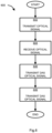
- Figure 6 shows a method 600 according to an exemplary embodiment.
- the method 600 is of monitoring an optical fibre cable assembly, the method comprising:
Landscapes
- Physics & Mathematics (AREA)
- General Physics & Mathematics (AREA)
- Electromagnetism (AREA)
- Engineering & Computer Science (AREA)
- Computer Networks & Wireless Communication (AREA)
- Signal Processing (AREA)
- Optical Communication System (AREA)
Priority Applications (4)
| Application Number | Priority Date | Filing Date | Title |
|---|---|---|---|
| EP23275039.8A EP4428505A1 (fr) | 2023-03-10 | 2023-03-10 | Appareil et procédé |
| EP24710479.7A EP4677776A1 (fr) | 2023-03-10 | 2024-02-27 | Appareil et procédé |
| GB2402720.3A GB2628710A (en) | 2023-03-10 | 2024-02-27 | Apparatus and method |
| PCT/GB2024/050521 WO2024189309A1 (fr) | 2023-03-10 | 2024-02-27 | Appareil et procédé |
Applications Claiming Priority (1)
| Application Number | Priority Date | Filing Date | Title |
|---|---|---|---|
| EP23275039.8A EP4428505A1 (fr) | 2023-03-10 | 2023-03-10 | Appareil et procédé |
Publications (1)
| Publication Number | Publication Date |
|---|---|
| EP4428505A1 true EP4428505A1 (fr) | 2024-09-11 |
Family
ID=85571294
Family Applications (1)
| Application Number | Title | Priority Date | Filing Date |
|---|---|---|---|
| EP23275039.8A Pending EP4428505A1 (fr) | 2023-03-10 | 2023-03-10 | Appareil et procédé |
Country Status (1)
| Country | Link |
|---|---|
| EP (1) | EP4428505A1 (fr) |
Citations (5)
| Publication number | Priority date | Publication date | Assignee | Title |
|---|---|---|---|---|
| EP1065811A2 (fr) | 1999-06-30 | 2001-01-03 | Nortel Networks Limited | Amplificateurs optiques |
| US8311409B2 (en) * | 2009-06-12 | 2012-11-13 | National Taiwan University Of Science And Technology | Signal switching module for optical network monitoring and fault locating |
| EP3361225A1 (fr) * | 2017-02-09 | 2018-08-15 | Aragon Photonics Labs, S.L.U. | Module, système et procédé de détection de vibration répartie |
| US20210266065A1 (en) * | 2020-02-24 | 2021-08-26 | Nec Laboratories America, Inc | Distributed sensing over switched optical fiber networks |
| US20220146287A1 (en) * | 2020-11-11 | 2022-05-12 | Alibaba Group Holding Limited | System and method for fiber sensing |
-
2023
- 2023-03-10 EP EP23275039.8A patent/EP4428505A1/fr active Pending
Patent Citations (5)
| Publication number | Priority date | Publication date | Assignee | Title |
|---|---|---|---|---|
| EP1065811A2 (fr) | 1999-06-30 | 2001-01-03 | Nortel Networks Limited | Amplificateurs optiques |
| US8311409B2 (en) * | 2009-06-12 | 2012-11-13 | National Taiwan University Of Science And Technology | Signal switching module for optical network monitoring and fault locating |
| EP3361225A1 (fr) * | 2017-02-09 | 2018-08-15 | Aragon Photonics Labs, S.L.U. | Module, système et procédé de détection de vibration répartie |
| US20210266065A1 (en) * | 2020-02-24 | 2021-08-26 | Nec Laboratories America, Inc | Distributed sensing over switched optical fiber networks |
| US20220146287A1 (en) * | 2020-11-11 | 2022-05-12 | Alibaba Group Holding Limited | System and method for fiber sensing |
Non-Patent Citations (1)
| Title |
|---|
| IP EZRA ET AL: "Distributed fiber sensor network using telecom cables as sensing media: technology advancements and applications", JOURNAL OF OPTICAL COMMUNICATIONS AND NETWORKING, IEEE, USA, vol. 14, no. 1, 1 January 2022 (2022-01-01), XP011886622, ISSN: 1943-0620, [retrieved on 20211102], DOI: 10.1364/JOCN.439175 * |
Similar Documents
| Publication | Publication Date | Title |
|---|---|---|
| US11463171B2 (en) | Bidirectional optical communication and sensing WDM architecture using same fiber transmission band | |
| EP1564913A2 (fr) | Procédé et dispositif actif de surveillance de pertes de fibre optique | |
| US6493133B1 (en) | System and method for increasing capacity of undersea cables | |
| EP1156607B1 (fr) | Egaliseur de puissance de rayonnement | |
| US20020131116A1 (en) | Optical add-drop multiplexer | |
| KR20010075159A (ko) | 파장 분할 다중화 시스템에서 신호 손실을 검출하기 위한방법 및 시스템 | |
| EP0964536A2 (fr) | Système détecteur d'erreur pour un système optique de transmission amplifié | |
| US20120248287A1 (en) | Optical amplification apparatus, method for controlling same, optical receiver station, and optical transmission system | |
| JPH09191291A (ja) | 光伝送路監視方法および波長多重光伝送装置 | |
| JPH09116492A (ja) | 波長多重光増幅中継伝送方法およびその装置 | |
| JPH10135549A (ja) | 波長多重光伝送用光増幅装置 | |
| US10567081B2 (en) | Transmission system and transmission method | |
| EP2685641A1 (fr) | Étage d'amplification optique pour surveillance otdr et procédé associé et système de surveillance otdr d'une liaison de communication optique | |
| EP3614581A1 (fr) | Système de transmission optique bidirectionnelle et procédé de transmission optique bidirectionnelle | |
| KR20010034668A (ko) | Wdm 전송 중계기, wdm 전송 시스템, 및 wdm 전송방법 | |
| EP4428505A1 (fr) | Appareil et procédé | |
| JP4588257B2 (ja) | ラマン増幅を用いる光増幅システム | |
| WO2024189309A1 (fr) | Appareil et procédé | |
| US11128380B2 (en) | Signal light interruption detection device, optical amplifier, optical wavelength multiplex transmission device, and optical wavelength multiplex transmission system | |
| US12571673B2 (en) | Multi-span optical fiber das system with amplified-filtered loopback (AFLB) | |
| KR100317133B1 (ko) | 양방향애드/드롭다중화기를구비한양방향파장분할다중방식자기치유광통신망 | |
| JP3967198B2 (ja) | 伝送装置及び伝送システム及び伝送方法及び伝送プログラム及び伝送プログラムを記録したコンピュータ読み取り可能な記録媒体 | |
| JP4405250B2 (ja) | 信号光反射阻止回路および光伝送システム | |
| KR102930798B1 (ko) | 분리 필터 및 이를 이용한 양자 통신 시스템 | |
| JP3149915B2 (ja) | 波長多重光監視方式および波長多重光監視装置 |
Legal Events
| Date | Code | Title | Description |
|---|---|---|---|
| PUAI | Public reference made under article 153(3) epc to a published international application that has entered the european phase |
Free format text: ORIGINAL CODE: 0009012 |
|
| STAA | Information on the status of an ep patent application or granted ep patent |
Free format text: STATUS: THE APPLICATION HAS BEEN PUBLISHED |
|
| AK | Designated contracting states |
Kind code of ref document: A1 Designated state(s): AL AT BE BG CH CY CZ DE DK EE ES FI FR GB GR HR HU IE IS IT LI LT LU LV MC ME MK MT NL NO PL PT RO RS SE SI SK SM TR |