EP4428622A1 - Tourbillonmechanismus für uhrwerk - Google Patents
Tourbillonmechanismus für uhrwerk Download PDFInfo
- Publication number
- EP4428622A1 EP4428622A1 EP23160313.5A EP23160313A EP4428622A1 EP 4428622 A1 EP4428622 A1 EP 4428622A1 EP 23160313 A EP23160313 A EP 23160313A EP 4428622 A1 EP4428622 A1 EP 4428622A1
- Authority
- EP
- European Patent Office
- Prior art keywords
- cage
- wheel
- tourbillon mechanism
- time division
- fractions
- Prior art date
- Legal status (The legal status is an assumption and is not a legal conclusion. Google has not performed a legal analysis and makes no representation as to the accuracy of the status listed.)
- Withdrawn
Links
Images




Classifications
-
- G—PHYSICS
- G04—HOROLOGY
- G04B—MECHANICALLY-DRIVEN CLOCKS OR WATCHES; MECHANICAL PARTS OF CLOCKS OR WATCHES IN GENERAL; TIME PIECES USING THE POSITION OF THE SUN, MOON OR STARS
- G04B17/00—Mechanisms for stabilising frequency
- G04B17/20—Compensation of mechanisms for stabilising frequency
- G04B17/28—Compensation of mechanisms for stabilising frequency for the effect of imbalance of the weights, e.g. tourbillon
- G04B17/285—Tourbillons or carrousels
Definitions
- the present invention relates to the field of watchmaking. It concerns, more particularly, a tourbillon mechanism for a watch movement.
- the document EP0973076 reveals a tourbillon mechanism in which the cage carries a small seconds hand. This hand is driven by a setting wheel which meshes with the fixed wheel, and to this end, when the cage pivots, the hand pivots relative to the latter since the setting wheel rolls on the fixed wheel.
- the aim of the invention is therefore to provide a tourbillon mechanism for a timepiece in which the aforementioned defects are at least partially overcome.
- said tourbillon mechanism further comprises a member for indicating the fractions of a time division, such as a hand, a disc, a segment or the like, which is kinematically connected to said escapement wheel and is thus driven by the latter via an ad hoc kinematic chain.
- Said time division may be seconds (in which case the member for indicating the fractions of a time division is a member for indicating fractions of seconds), but other time divisions such as minutes or hours are also possible.
- a drive wheel is provided, integral in rotation with said escapement wheel and arranged to drive said member for indicating the fractions of a time division.
- said member for indicating the fractions of a time division is pivotally mounted on a frame element provided for this purpose, its pivot axis typically being coaxial with that of the cage, but this is not obligatory.
- said member for indicating the fractions of a time division is pivotally mounted on said rotating cage. This arrangement is particularly advantageous when the cage is mounted in a flying manner, i.e. supported exclusively on the bottom side, but conventional pivoting between bearings is also possible.
- said organ for indicating the fractions of a time division is superimposed on a dial carried by said rotating cage, which makes the indication particularly clear.
- said dial is integral in rotation with said rotating cage and consequently pivots with the latter.
- said dial is pivotally mounted on said rotating cage and is arranged so as to have a constant orientation relative to a fixed and therefore non-rotating frame element.
- This dial is therefore of the “orbital dial” type, the origin of its scale or its markings of which keeps the same orientation relative to the 12 o’clock-6 o’clock axis of the timepiece in which the tourbillon mechanism is integrated. It should be noted that the main dial of the timepiece can be oriented along the 12 o’clock-6 o’clock axis, but also according to any desired orientation.
- said constant orientation is ensured by means of a gear train carried by said rotating cage and driven from a pinion which is driven by a drive wheel which is integral in rotation with said escapement wheel, said pinion being kinematically connected to a wheel integral in rotation with said dial.
- said constant orientation can be ensured by means of fixed teeth carried by a frame element which is kinematically connected to a wheel integral in rotation with said dial.
- the kinematic connection between said escape wheel and said member for indicating the fractions of a time division is formed by a chain of gears comprising mobiles all having teeth having a module of less than 0.05 mm, but it goes without saying that any suitable module can alternatively be used.
- THE figures 1 And 2 illustrate a first embodiment of a tourbillon mechanism 1 according to the invention.
- the term “tourbillon” is to be understood in its broad sense, encompassing carousels, multi-axis tourbillons, flying tourbillons, pivoted tourbillons, etc.
- the tourbillon mechanism 1 is provided with a rotating cage 3, arranged to be pivotally mounted on a frame element (not shown) and rotated by means of a drive source M of any known type (typically a barrel housing a mainspring), which cooperates with a cage toothing 5 by means of an ad hoc gear train.
- the cage toothing 5 is a pinion located on the bottom side of the cage 3, but other toothings are possible, such as, for example, a peripheral toothing (internal or external).
- the cage 3 is pivoted in a flying manner, but a conventional pivoting between bearings is also possible.
- the cage 3 can alternatively be formed of a board.
- cage 3 houses a balance-spring oscillator 7, here pivoted inside cage 3, but one, the other or all of its pivots can be positioned on a frame element alternatively.
- a conventional balance-spring oscillator 7 is illustrated here, any type of balance and balance spring can be used.
- balance-spring 7 is illustrated as having an axis of rotation coaxial with that of the cage 3, but this can alternatively be off-center and therefore not confused with the axis of rotation of the cage 3.
- the angle formed by the axis of the display member 23 and that of the cage 3 are parallel in this case, but they could also be non-parallel, in the case where one of the two (or both) is inclined relative to the vertical (i.e. relative to a direction perpendicular to the plane of movement).
- the cage also carries an escapement 9, comprising an escapement wheel 11 and an anchor 13, which cooperate with each other and with the sprung balance in a known manner, in order to maintain the oscillations of the latter.
- the escapement 9 is of the Swiss anchor type in the illustrated embodiment, but can take any known form (detent, Omega-Daniels, etc.)
- the escape wheel 11 is rotationally secured to an escape pinion 15, in order to form an escape wheel.
- Said pinion 15 meshes directly with a toothing 17 mounted on a frame element (not shown) in order to pivot the escape wheel about its axis of rotation when the cage 3 pivots.
- the toothing 17 is fixed relative to the frame, but can alternatively be arranged to be driven by rotation.
- the rotation speed of cage 3 can be chosen at will, but is typically one revolution per minute, in order to be able to indicate the seconds by means of an index 19.
- the escapement wheel also carries a drive wheel 21, which is also rotationally integral with the escapement wheel 11 and the escapement pinion 15.
- This drive wheel rotates a member for indicating the fractions of a time division 23, pivotally mounted on the cage 3.
- said time division is seconds
- the member for indicating a fraction of a time division 23 is a member for fractions of seconds 23 (i.e. which indicates fractions of a second)
- this specific terminology being used in the detailed description in order to simplify the reading in connection with the illustrated embodiments.
- fractions of other time divisions such as minutes, hours, or the like, indicating fractions of a minute, hour, or the like
- the gear ratios being, of course, adapted accordingly. This adaptation is within the abilities of those skilled in the art and therefore does not need to be described in detail.
- a transmission wheel 25, also pivotally mounted on the cage 3, serves to transmit rotation from the drive wheel 21 to the fraction-second indicating member 23, which takes the form of a needle here, but which could alternatively take the form of a disk, a segment or any other suitable form.
- This fraction-second indicating member 23 moves in front of markings, indexes or the like 29 carried by the cage 3, but this is not obligatory.
- the gear ratio between the drive wheel 21 and the fractional second display member 23 can be chosen at will in order to animate the latter with a desired rotation speed around its axis of rotation.
- the position of the axis of rotation of the fractional second display member 23 can also be chosen at will, by being off-centered relative to the cage 3 as illustrated in the figures 1 And 2 , or by being coaxial with it.
- the fraction-of-second display member 23 can simply be integral in rotation with the escape wheel 21.
- the drive wheel 21, the toothed members of the transmission wheel set 25 and the wheel 27 which is integral in rotation with the fraction-of-seconds indicator member 23 can all have a tooth module of less than 0.05 mm, which allows for smoother and less jerky drive.
- the fraction-second indicator member 23 pivots around its own axis of rotation relative to the cage 3, under the drive of the escapement wheel 11, 15 and as a function of the rotations of the latter.
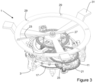
- THE figures 3 And 4 illustrate a second embodiment of a tourbillon mechanism 1 according to the invention, which differs from that of figures 1 And 2 in that the fractional second indicating member 23 is not carried by the cage 3, but by a support 31 which is integral in rotation with the frame and/or the dial, the axis of rotation of the fractional second indicating member 23 being coaxial with that of the cage 3.
- FIG 5 further illustrates an embodiment of a tourbillon mechanism 1 according to the invention, which differs from that of the figures 1 And 2 in that the markings or indexes 29 are carried by an orbital dial 33, off-center with respect to the axis of rotation of the cage 3 and arranged to pivot about its own axis of rotation so as to maintain the same orientation with respect to the frame and/or the main dial of the timepiece in which said tourbillon mechanism is integrated.
- the orbital dial 33 is mounted so as to be able to rotate on said cage 3 and is integral in rotation with a wheel 35 which is driven in rotation by means of a pinion 37 integral in rotation with the transmission mobile 25 by means of a return 39, also pivotally mounted on said cage by means of an axis and pivots not illustrated.
- a pinion 37 integral in rotation with the transmission mobile 25 by means of a return 39
- the pinion 37, the return 39 and the wheel 35 have been represented by their pitch circles, their teeth not having been drawn.
- the gear ratio between said pinion 37 and said wheel 35 is chosen such that said orbital dial 33 completes one revolution around its own axis of rotation in the same period, but in the opposite direction to said cage 3 to maintain its orientation relative to the frame and/or the main dial.
- FIG. 6 further illustrates an embodiment of a tourbillon mechanism according to the invention, also with orbital dial 33. This embodiment differs from that of the figure 5 with regard to the drive of the pivoting of the orbital dial 33 around its own axis of rotation.
- a pair of references kinematically connect the wheel 39 to a fixed toothing 45 mounted integral in rotation with a frame element (not illustrated).
- the elements 39, 41, 43 and 45 have been represented by their pitch circles, and the axes of the references 41, 43 have not been represented.
- the gear ratio between the fixed teeth and the wheel 39 is chosen such that said orbital dial 33 completes a revolution around its own axis of rotation in the same period, but in the opposite direction to said cage 3 to maintain its orientation relative to the frame and/or the main dial.
- the entire range of materials used in contemporary watchmaking can be considered (metals, non-metals such as silicon, silicon compounds, synthetic diamond, sapphire, structurable glasses, ceramics, glass-ceramics, metallic glasses, polymers, composites, materials that can be manufactured additively, etc.).
- metals non-metals such as silicon, silicon compounds, synthetic diamond, sapphire, structurable glasses, ceramics, glass-ceramics, metallic glasses, polymers, composites, materials that can be manufactured additively, etc.
- flexible pivots can be used for elements where this makes technical sense.
Landscapes
- Physics & Mathematics (AREA)
- General Physics & Mathematics (AREA)
- Toys (AREA)
- Transmission Devices (AREA)
Priority Applications (4)
| Application Number | Priority Date | Filing Date | Title |
|---|---|---|---|
| EP23160313.5A EP4428622A1 (de) | 2023-03-07 | 2023-03-07 | Tourbillonmechanismus für uhrwerk |
| JP2025546270A JP2026506916A (ja) | 2023-03-07 | 2024-03-04 | 時計用ムーブメントのためのトゥールビヨンまたはカルーセル機構 |
| PCT/EP2024/055601 WO2024184310A1 (fr) | 2023-03-07 | 2024-03-04 | Mecanisme de tourbillon ou de carrousel pour mouvement horloger |
| EP24708215.9A EP4677419A1 (de) | 2023-03-07 | 2024-03-04 | Tourbillon- oder karussellmechanismus für uhrwerk |
Applications Claiming Priority (1)
| Application Number | Priority Date | Filing Date | Title |
|---|---|---|---|
| EP23160313.5A EP4428622A1 (de) | 2023-03-07 | 2023-03-07 | Tourbillonmechanismus für uhrwerk |
Publications (1)
| Publication Number | Publication Date |
|---|---|
| EP4428622A1 true EP4428622A1 (de) | 2024-09-11 |
Family
ID=85511191
Family Applications (2)
| Application Number | Title | Priority Date | Filing Date |
|---|---|---|---|
| EP23160313.5A Withdrawn EP4428622A1 (de) | 2023-03-07 | 2023-03-07 | Tourbillonmechanismus für uhrwerk |
| EP24708215.9A Pending EP4677419A1 (de) | 2023-03-07 | 2024-03-04 | Tourbillon- oder karussellmechanismus für uhrwerk |
Family Applications After (1)
| Application Number | Title | Priority Date | Filing Date |
|---|---|---|---|
| EP24708215.9A Pending EP4677419A1 (de) | 2023-03-07 | 2024-03-04 | Tourbillon- oder karussellmechanismus für uhrwerk |
Country Status (3)
| Country | Link |
|---|---|
| EP (2) | EP4428622A1 (de) |
| JP (1) | JP2026506916A (de) |
| WO (1) | WO2024184310A1 (de) |
Citations (3)
| Publication number | Priority date | Publication date | Assignee | Title |
|---|---|---|---|---|
| EP0973076A1 (de) | 1998-07-16 | 2000-01-19 | Eta SA Fabriques d'Ebauches | Uhr mit Tourbillon |
| CH711774B1 (de) * | 2011-05-23 | 2017-05-15 | Bessem & Handl Sàrl | Stellvorrichtung für ein Uhrwerk. |
| CH711477B1 (de) * | 2015-08-31 | 2021-11-15 | Glashuetter Uhrenbetrieb Gmbh | Mechanisches Uhrwerk mit einem einstellbaren Tourbillon. |
-
2023
- 2023-03-07 EP EP23160313.5A patent/EP4428622A1/de not_active Withdrawn
-
2024
- 2024-03-04 EP EP24708215.9A patent/EP4677419A1/de active Pending
- 2024-03-04 JP JP2025546270A patent/JP2026506916A/ja active Pending
- 2024-03-04 WO PCT/EP2024/055601 patent/WO2024184310A1/fr not_active Ceased
Patent Citations (3)
| Publication number | Priority date | Publication date | Assignee | Title |
|---|---|---|---|---|
| EP0973076A1 (de) | 1998-07-16 | 2000-01-19 | Eta SA Fabriques d'Ebauches | Uhr mit Tourbillon |
| CH711774B1 (de) * | 2011-05-23 | 2017-05-15 | Bessem & Handl Sàrl | Stellvorrichtung für ein Uhrwerk. |
| CH711477B1 (de) * | 2015-08-31 | 2021-11-15 | Glashuetter Uhrenbetrieb Gmbh | Mechanisches Uhrwerk mit einem einstellbaren Tourbillon. |
Also Published As
| Publication number | Publication date |
|---|---|
| EP4677419A1 (de) | 2026-01-14 |
| JP2026506916A (ja) | 2026-02-27 |
| WO2024184310A1 (fr) | 2024-09-12 |
Similar Documents
| Publication | Publication Date | Title |
|---|---|---|
| EP2275880A1 (de) | Uhrwerk | |
| CH687795B5 (fr) | Piece d'horlogerie mecanique pourvue d'un tourbillon. | |
| WO2013004782A1 (fr) | Piece d'horlogerie | |
| EP2906996A1 (de) | Uhr | |
| EP2376986B1 (de) | Uhrwerk mit automatischer aufzugvorrichtung und bewegungshemmung | |
| EP1706796A1 (de) | Uhr mit zwei tourbillon uhrwerken | |
| WO2021023710A1 (fr) | Piece de joaillerie ou bijouterie comprenant un mecanisme d'animation d'un objet | |
| EP4113221A1 (de) | Armbanduhr, die ein zifferblatt mit einem festen teil und einem beweglichen teil umfasst | |
| EP3671363B1 (de) | Uhrwerk und uhr, die ein solches uhrwerk umfasst | |
| WO2014177290A1 (fr) | Piece d'horlogerie comprenant un dispositif d'affichage de quantieme | |
| EP3772674B1 (de) | Schmuck- oder juwelier-artikel umfassend einen animationsmechanismus eines objekts | |
| EP3764171B1 (de) | Anzeigemechanismus eines uhranzeigewerts | |
| CH718392A1 (fr) | Pièce d'horlogerie avec un rouage comprenant un train d'engrenage différentiel à satellite. | |
| CH720585A2 (fr) | Mécanisme de tourbillon pour mouvement horloger | |
| WO2024184310A1 (fr) | Mecanisme de tourbillon ou de carrousel pour mouvement horloger | |
| CH700958A2 (fr) | Montre a mouvement mobile. | |
| CH716486A2 (fr) | Mécanisme d'animation d'un objet pour pièce de joaillerie ou de bijouterie. | |
| EP3501842A1 (de) | Anzeigevorrichtung mit rollen | |
| EP4202573B1 (de) | Mechanismus zur animation eines objekts für uhr | |
| EP3798741B1 (de) | Uhrwerk | |
| EP0504623A1 (de) | Doppelzeitzone mit durchquerender Achse und Zeiteinstellung über die Krone | |
| WO2021063953A1 (fr) | Mouvement horloger | |
| CH719288A2 (fr) | Mécanisme d'animation d'un objet pour pièce d'horlogerie. | |
| CH720191A2 (fr) | Pièce d'horlogerie mécanique à tourbillon surélevé | |
| WO2023285101A1 (fr) | Mecanisme d'affichage pour piece d'horlogerie |
Legal Events
| Date | Code | Title | Description |
|---|---|---|---|
| PUAI | Public reference made under article 153(3) epc to a published international application that has entered the european phase |
Free format text: ORIGINAL CODE: 0009012 |
|
| STAA | Information on the status of an ep patent application or granted ep patent |
Free format text: STATUS: THE APPLICATION HAS BEEN PUBLISHED |
|
| AK | Designated contracting states |
Kind code of ref document: A1 Designated state(s): AL AT BE BG CH CY CZ DE DK EE ES FI FR GB GR HR HU IE IS IT LI LT LU LV MC ME MK MT NL NO PL PT RO RS SE SI SK SM TR |
|
| STAA | Information on the status of an ep patent application or granted ep patent |
Free format text: STATUS: THE APPLICATION IS DEEMED TO BE WITHDRAWN |
|
| 18D | Application deemed to be withdrawn |
Effective date: 20250312 |