EP4428633A1 - Procédé de fonctionnement d'un système d'automatisation redondant et système d'automatisation redondant - Google Patents
Procédé de fonctionnement d'un système d'automatisation redondant et système d'automatisation redondant Download PDFInfo
- Publication number
- EP4428633A1 EP4428633A1 EP23160779.7A EP23160779A EP4428633A1 EP 4428633 A1 EP4428633 A1 EP 4428633A1 EP 23160779 A EP23160779 A EP 23160779A EP 4428633 A1 EP4428633 A1 EP 4428633A1
- Authority
- EP
- European Patent Office
- Prior art keywords
- group
- tasks
- processor unit
- automation system
- unit
- Prior art date
- Legal status (The legal status is an assumption and is not a legal conclusion. Google has not performed a legal analysis and makes no representation as to the accuracy of the status listed.)
- Withdrawn
Links
Images
Classifications
-
- G—PHYSICS
- G05—CONTROLLING; REGULATING
- G05B—CONTROL OR REGULATING SYSTEMS IN GENERAL; FUNCTIONAL ELEMENTS OF SUCH SYSTEMS; MONITORING OR TESTING ARRANGEMENTS FOR SUCH SYSTEMS OR ELEMENTS
- G05B9/00—Safety arrangements
- G05B9/02—Safety arrangements electric
- G05B9/03—Safety arrangements electric with multiple-channel loop, i.e. redundant control systems
-
- G—PHYSICS
- G05—CONTROLLING; REGULATING
- G05B—CONTROL OR REGULATING SYSTEMS IN GENERAL; FUNCTIONAL ELEMENTS OF SUCH SYSTEMS; MONITORING OR TESTING ARRANGEMENTS FOR SUCH SYSTEMS OR ELEMENTS
- G05B19/00—Program-control systems
- G05B19/02—Program-control systems electric
- G05B19/04—Program control other than numerical control, i.e. in sequence controllers or logic controllers
- G05B19/042—Program control other than numerical control, i.e. in sequence controllers or logic controllers using digital processors
- G05B19/0428—Safety, monitoring
-
- G—PHYSICS
- G05—CONTROLLING; REGULATING
- G05B—CONTROL OR REGULATING SYSTEMS IN GENERAL; FUNCTIONAL ELEMENTS OF SUCH SYSTEMS; MONITORING OR TESTING ARRANGEMENTS FOR SUCH SYSTEMS OR ELEMENTS
- G05B2219/00—Program-control systems
- G05B2219/20—Pc systems
- G05B2219/24—Pc safety
- G05B2219/24186—Redundant processors are synchronised
Definitions
- the invention relates to a redundant automation system which comprises at least a first hardware unit and a second hardware unit, wherein the first hardware unit comprises a first processor unit and a second processor unit, and the second hardware unit comprises a third processor unit and a fourth processor unit, wherein the first hardware unit is designed to execute a first group of tasks by means of the first processor unit and a second group of tasks by means of the second processor unit and to output corresponding output signals to an industrial process controlled by the redundant automation system, wherein the second hardware unit is designed to execute a third group of tasks by means of the third processor unit and a fourth group of tasks by means of the fourth processor unit and to output corresponding output signals to an industrial process controlled by the redundant automation system or to receive the corresponding sensor signals from the industrial process, wherein the redundant automation system is designed to execute the tasks of the third group and the fourth group in the event of a failure of the first hardware unit and to output the corresponding output signals to an industrial process controlled by the redundant automation system or to receive the corresponding sensor signals from the industrial process, and wherein the redundant Automation
- the invention relates to a system which comprises a system for operating and monitoring the industrial process and a redundant automation system.
- the invention relates to a method for operating a redundantly designed automation system.
- H systems highly available solutions
- a synchronization connection In principle, both subsystems can read and/or write to the peripheral units connected to this H system.
- One of the two subsystems is the leader in terms of the peripherals connected to the system.
- the peripherals are connected in accordance with standardized communication protocols for redundant field buses.
- the EP 2 667 269 A1 discloses an operating method for a redundant automation system.
- Redundant automation systems generally face the problem of processing incoming and outgoing data streams in a synchronized manner. This essentially means that incoming data streams are duplicated on both redundant subsystems and outgoing data streams that arise in both redundant subsystems must be separated. With previously known redundancy solutions, this is associated with a correspondingly high computing time load on the two subsystems.
- H systems are characterized by the fact that one and the same automation task is carried out redundantly on several different hardware units, but only the output signals of one of the hardware units are actually used to control the industrial process. This makes it possible for the other hardware unit used to control the industrial process to take over control of the process without delay or at least almost without delay if the hardware unit used to control the industrial process fails.
- the hardware units that each process the automation task must be synchronized. It must be ensured that the hardware units work with the same data and process the same data in the same way.
- a highly available connection to a communication partner such as an operator station is used in known redundant automation systems. If one transport connection fails, the other can be switched over immediately, as the data storage in both modules of the automation system is synchronized. This means, for example, that the order can be received via one partial connection, but the acknowledgement can be sent back via the other partial connection of the highly available connection.
- the required synchronization of the highly synchronized data storage represents a throughput brake, which is typically a factor of 3.
- the invention is therefore based on the object of specifying a method for operating a redundantly designed automation system and a corresponding redundant automation system, which reduce the resource expenditure caused by the automation system.
- the respective hardware unit can be divided into two processor units in terms of hardware or software.
- the division is therefore generally seen as a "logical" division.
- the automation system according to the invention is designed in a manner known per se to enable redundant operation, whereby the two hardware units can each take over the tasks of the other hardware unit if the latter is temporarily or no longer functional. In order to synchronize the two hardware units, they are connected via a first and a second synchronization connection.
- the redundant design of the components of the automation system is intended to ensure continuous operation of the automation system, even in the event of a fault.
- the automation system is characterized in that the first synchronization connection is designed for a time-delayed comparison of the tasks of the first group and the third group, and the second synchronization connection is designed for a highly synchronous comparison of the tasks of the second group and the fourth group.
- the first processor unit and third processor unit are preferably intended for tasks of communication with external systems such as an operator station.
- the first group of tasks and the third group of tasks are therefore preferably communication tasks that do not result in output signals to the controlled industrial process.
- the second processor unit and the fourth processor unit are preferably intended to carry out tasks for controlling the industrial process and to output corresponding output signals to the industrial process controlled by the redundant automation system.
- the second and fourth (control) processor units are synchronized in a highly synchronous manner to implement the necessary redundancy functionality.
- the term "highly synchronous" means that the processing status of the second and fourth (control) processor units is identical at all times with a relatively low latency.
- the highly synchronous synchronization of the tasks of the second group and the fourth group via the second synchronization connection can have a time delay of less than 1 millisecond. This means that the two processor units process the identical tasks with a delay/latency of less than 1 millisecond.
- the highly synchronous synchronization of the second synchronization connection is advantageously initiated by the occurrence of a new task of the second or fourth group. In this context, one speaks of an event-synchronous coupling of the two second and fourth (control) processor units.
- the first and third (communication) processor units for example, have a time delay of more than 10 milliseconds when synchronizing tasks at different times.
- the synchronization of the first and third (communication) processor units is not event-synchronized. Rather, the synchronization can be delayed until there is capacity for the synchronization on the synchronization connection.
- the adjustment between the first and third (communication) processor units within the scope of the invention is carried out by orders of magnitude, preferably at least one order of magnitude, less frequently than the adjustment/synchronization between the second and fourth (control) processor units.
- This allows the necessary communication effort of the automation system to be significantly reduced without, however, causing a loss of quality in the redundancy functionality.
- a further advantage of the modeling is that the probability that both first and third (communication) processor units will switch to the DEFECTIVE operating state at the same time (quasi-synchronized) is reduced; the availability of the first and third (communication) processor units increases.
- the first synchronization connection and the second synchronization connection use a common synchronization medium, in particular an optical fiber.
- a common synchronization medium in particular an optical fiber.
- Such an optical fiber is common for implementing a highly synchronous adjustment and can also be used in a particularly advantageous manner for the non-highly synchronous (time-delayed) adjustment of the first and third (communication) processor units.
- an additional synchronization medium is not necessary.
- a system which comprises a system for operating and monitoring the industrial process and a redundant automation system according to one of the preceding claims, wherein the system for operating and monitoring the industrial process is connected to the first processor unit of the first hardware unit via a system bus, which is in particular designed as Industrial Ethernet, and wherein the system for operating and monitoring the industrial process is connected to the third processor unit of the second hardware unit via the system bus, and wherein the second processor unit of the first hardware unit and the fourth processor unit of the second hardware unit are connectable to the industrial process.
- connection methods are used for the connection between the system for operating and monitoring (operator station). These standardized connection methods are characterized by the fact that they do not have to be designed to be highly available. To do this, the system for operating and monitoring must establish two standard connections to the first and third (communication) processor units in order to be able to switch to the other standard connection in the event of a failure. The communication tasks may have to be repeated. It is particularly preferred that the system for operating and monitoring the industrial process is communicatively connected to the first processor unit and the third processor unit of the redundant automation system using a communication connection based on TCP/IP or TLS.
- a method for operating a redundantly designed automation system which comprises at least a first hardware unit and a second hardware unit, wherein the first hardware unit comprises a first processor unit and a second processor unit, and the second hardware unit comprises a third processor unit and a fourth processor unit, wherein the first hardware unit is designed to carry out a first group of tasks by means of the first processor unit and a second group of tasks by means of the second processor unit, wherein the second hardware unit is designed to carry out a third group of tasks by means of the third processor unit and a fourth group of tasks by means of the fourth processor unit, wherein the redundant automation system is designed to carry out the tasks of the third group and the fourth group in the event of a failure of the first hardware unit and to output corresponding output signals to an industrial process controlled by the redundant automation system, and wherein the redundant automation system is designed to carry out the tasks of the first and the second group in the event of a failure of the second hardware unit and to output corresponding To output output signals to the controlled industrial process, wherein the redundant automation system
- the method is characterized in that a time-delayed comparison of the tasks of the first group and the third group is carried out via the first synchronization connection, and a highly synchronous comparison of the tasks of the second group and the fourth group is carried out via the second synchronization connection.
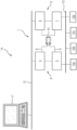
- the figure shows a system 14 with an operator station server 11 as a system for operating and monitoring an industrial process 10a, 10b, 10c, 10d and a redundant automation system 1.
- the automation system 1 has a first hardware unit 2 and a second hardware unit 3.
- the first hardware unit 2 comprises a first processor unit 4 and a second processor unit 5.
- the second hardware unit 3 comprises a third processor unit 6 and a fourth processor unit 7.
- the first processor unit 4 of the first hardware unit 4 is connected to the operator station server 11 via a system bus 12 (Industrial Ethernet).
- the third processor unit 6 is also connected to the operator station server 11 via the system bus 12.
- the second processor unit 5 and the fourth processor unit 7 are each connected to the industrial Process 10a, 10b, 10c, 10d are connected via a field bus 13.
- the first processor unit 4 and the second processor unit 5, and the third processor unit 6 and the fourth processor unit 7 are connected to one another.
- the first processor unit 4 is connected to the third processor unit via a first synchronization connection 8.
- the second processor unit 5 is connected to the fourth processor unit 7 via a second synchronization connection 9.
- the two synchronization connections 8, 9 jointly use an optical fiber 15 as a connection medium.
- the first and third processor units 4, 6 act as communication processors that implement communication between the automation system 1 and the operating and monitoring system 11.
- the second and fourth processor units 5, 7 act as control processors that control the industrial process 10a, 10b, 10c, 10d in a manner known per se.
- the two communication processor units 4, 6 automatically carry out a data comparison via the non-highly synchronous (time-delayed) coupling of the first synchronization connection 8 as soon as the coupling is available. There is no need to wait until the first hardware unit 2 and the second hardware unit 3 are in a synchronized state, which was previously necessary with known redundant automation systems.
- the data synchronization refers to projected data (if already loaded) and to dynamic data, e.g. system diagnostics. This data synchronization takes place continuously, e.g. when a project is loaded onto one of the communication processor units 4, 6.
- the system for operating and monitoring 11 then starts the previously loaded user program in the first control processor unit 5, e.g. using communication services using a standardized connection (for example using TCP/IP) via the first communication processor unit 4.
- communication jobs are executed in the first communication processor unit 4 or forwarded via an "Application Programming Interface" (API) to the second control processor unit 5 for reading or writing data access.
- API Application Programming Interface
- the result is returned via the API of the first communication processor unit 4 and a communication acknowledgment is created there.
- the acknowledgment is then returned via the system bus 12 to the system for operating and monitoring (operator station) 11.
- the automation system 1 or the control processor unit 5 is then in the RUN_SOLO operating state.
- the control processor unit 7 is in the STOP operating state.
- this event is made available to the first communication processor unit 4 via the API.
- the first communication processor unit 4 forwards the event to the third communication processor unit 6 via the non-highly synchronous (time-delayed) coupling 8.
- the event is then further processed locally in both communication processor units 4, 6 and, if necessary, the system for operating and monitoring (operator station) is informed via the standard connections of the communication processor units 4, 6.
- the results of the processing of the two control processor units 5, 7 are made available (highly synchronously) at the interfaces (APIs) in the direction of the first and third communication processor units 4, 6. Since this information provided contains the original requester, i.e. the first communication processor unit 4, only the corresponding first communication processor unit 4 is informed of the result, the event in the other API (here the third communication processor unit 6) is discarded.
- the further processing of the communication technology thus takes place only in the first communication processor unit 4, which sends the acknowledgment back to the system for operating and monitoring (operator station) 11 via the corresponding standard connection.
- An important advantage of the present invention is that read access can be carried out without a highly synchronous connection on the two control processor units 4, 6. Since read access represents a high proportion of the communication services (typically around 90%), a significant increase in performance can be achieved with an appropriate load distribution on the part of the system for operating and monitoring (operator station) 11 via the standard connections. In other words, with the present invention, only one of the two hardware units 2, 3 can be addressed by the system for operating and monitoring (operator station) 11 during a read operation, since the two communication processor units 4, 6 are not synchronized in a highly synchronous manner (with a time delay). It is sufficient for the system for operating and monitoring (operator station) 11 to address one of the two communication processor units 4, 6 for a read operation. This represents a significant advantage over known redundant automation systems.
- the system for operating and monitoring (operator station) 11 wants to read data that is only located on the two communication processor units 4, 6, e.g. system diagnostic data
- the corresponding job of the system for operating and monitoring (operator station) 11 can be processed without a data comparison and acknowledged by the respective communication processor unit 4, 6 of the system for operating and monitoring (operator station) 11.
- the system for operating and monitoring (operator station) 11 can also write data that is to be stored on both communication processor units 4, 6.
- the first communication processor unit 4 sends the received order to the third communication processor unit 6 via the non-highly synchronous (time-delayed) coupling 8.
- the date is then written to both communication processor units 4, 6.
- the acknowledgement of the third communication processor unit 6 is sent via the non-highly synchronous (time-delayed) coupling 8 to the first communication processor unit 4 and discarded there.
- the forwarded communication requests can receive suitable connection identifiers in order to be able to supply the acknowledgment to the corresponding communication processor unit 4, 6.
- the data structures are designed in such a way that they are identical on both communication processor units 4, 6.
- Events on a communication processor unit 4, 6 always occur on one side. These are generally system diagnostics events because, for example, a wire break in a peripheral module has been detected and reported.
- This one-sided event on a communication processor unit 4, 6 is communicated to the other communication processor unit 4, 6 via the non-highly synchronous (time-delayed) connection 8. In this way, the one-sided event can be processed promptly and locally by both communication processor units 4, 6.
- the duplicated event can be communicated to the system diagnostics as an alarm via all standard connections to the connected system for operating and monitoring (operator station) 11.
- the standard connections that end, for example, at the second hardware unit 3 are aborted, since the third control processor unit 6 changes to the STOP operating state.
- the standard connections can then be re-established and used.
- the connection termination can be limited, for example, to the standard connections with the identifier "M&C”.
- the system for operating and monitoring (operator station) 11 re-establishes these connections to the third communication processor unit 6.
- the communication services are transferred to the first via the non-highly synchronous (time-delayed) coupling 8.
- the data is forwarded to the communication processor unit 4 for processing as long as the fourth control processor unit 7 is in the STOP operating state.
- the other standard connections that do not have the "M&C" identifier could continue to run (e.g. "engineering" connections).
- the communication processor units 4, 6 and the control processor units 5, 7 can be combined (in pairs) in a single module, for example an industrial PC with a real-time operating system.
- the first (real) communication processor unit 4 can be assigned a second control processor unit 5, and the fourth control processor unit 7 to be assigned a virtual third communication processor unit 6, which runs on a high-performance server as a virtual machine.
- several virtual communication processor units 4, 6 can be instantiated on a high-performance computer, which are assigned to several real control processor units 5, 7.
- the real control processor units 5, 7 guarantee a high availability of the processing of the user program compared to the system process.
Landscapes
- Physics & Mathematics (AREA)
- General Physics & Mathematics (AREA)
- Engineering & Computer Science (AREA)
- Automation & Control Theory (AREA)
- Hardware Redundancy (AREA)
- Safety Devices In Control Systems (AREA)
Priority Applications (4)
| Application Number | Priority Date | Filing Date | Title |
|---|---|---|---|
| EP23160779.7A EP4428633A1 (fr) | 2023-03-08 | 2023-03-08 | Procédé de fonctionnement d'un système d'automatisation redondant et système d'automatisation redondant |
| EP24704343.3A EP4643188A1 (fr) | 2023-03-08 | 2024-02-05 | Procédé de fonctionnement d'un système d'automatisation redondant, et système d'automatisation redondant |
| CN202480017375.0A CN120858323A (zh) | 2023-03-08 | 2024-02-05 | 用于运行冗余自动化系统的方法和冗余自动化系统 |
| PCT/EP2024/052681 WO2024183992A1 (fr) | 2023-03-08 | 2024-02-05 | Procédé de fonctionnement d'un système d'automatisation redondant, et système d'automatisation redondant |
Applications Claiming Priority (1)
| Application Number | Priority Date | Filing Date | Title |
|---|---|---|---|
| EP23160779.7A EP4428633A1 (fr) | 2023-03-08 | 2023-03-08 | Procédé de fonctionnement d'un système d'automatisation redondant et système d'automatisation redondant |
Publications (1)
| Publication Number | Publication Date |
|---|---|
| EP4428633A1 true EP4428633A1 (fr) | 2024-09-11 |
Family
ID=85569549
Family Applications (2)
| Application Number | Title | Priority Date | Filing Date |
|---|---|---|---|
| EP23160779.7A Withdrawn EP4428633A1 (fr) | 2023-03-08 | 2023-03-08 | Procédé de fonctionnement d'un système d'automatisation redondant et système d'automatisation redondant |
| EP24704343.3A Pending EP4643188A1 (fr) | 2023-03-08 | 2024-02-05 | Procédé de fonctionnement d'un système d'automatisation redondant, et système d'automatisation redondant |
Family Applications After (1)
| Application Number | Title | Priority Date | Filing Date |
|---|---|---|---|
| EP24704343.3A Pending EP4643188A1 (fr) | 2023-03-08 | 2024-02-05 | Procédé de fonctionnement d'un système d'automatisation redondant, et système d'automatisation redondant |
Country Status (3)
| Country | Link |
|---|---|
| EP (2) | EP4428633A1 (fr) |
| CN (1) | CN120858323A (fr) |
| WO (1) | WO2024183992A1 (fr) |
Citations (5)
| Publication number | Priority date | Publication date | Assignee | Title |
|---|---|---|---|---|
| EP0907912B1 (fr) | 1996-06-24 | 2000-05-03 | Siemens Aktiengesellschaft | Procede de synchronisation |
| EP2657797A1 (fr) | 2012-04-27 | 2013-10-30 | Siemens Aktiengesellschaft | Procédé de fonctionnement d'un système d'automatisation redondant |
| EP2667269A1 (fr) | 2012-05-25 | 2013-11-27 | Siemens Aktiengesellschaft | Procédé de fonctionnement d'un système d'automatisation redondant |
| EP3872582A1 (fr) * | 2020-02-26 | 2021-09-01 | Siemens Aktiengesellschaft | Système d'automatisation conçu de manière redondante |
| EP3872583A1 (fr) * | 2020-02-26 | 2021-09-01 | Siemens Aktiengesellschaft | Système d'automatisation conçu de manière redondante |
-
2023
- 2023-03-08 EP EP23160779.7A patent/EP4428633A1/fr not_active Withdrawn
-
2024
- 2024-02-05 CN CN202480017375.0A patent/CN120858323A/zh active Pending
- 2024-02-05 EP EP24704343.3A patent/EP4643188A1/fr active Pending
- 2024-02-05 WO PCT/EP2024/052681 patent/WO2024183992A1/fr not_active Ceased
Patent Citations (5)
| Publication number | Priority date | Publication date | Assignee | Title |
|---|---|---|---|---|
| EP0907912B1 (fr) | 1996-06-24 | 2000-05-03 | Siemens Aktiengesellschaft | Procede de synchronisation |
| EP2657797A1 (fr) | 2012-04-27 | 2013-10-30 | Siemens Aktiengesellschaft | Procédé de fonctionnement d'un système d'automatisation redondant |
| EP2667269A1 (fr) | 2012-05-25 | 2013-11-27 | Siemens Aktiengesellschaft | Procédé de fonctionnement d'un système d'automatisation redondant |
| EP3872582A1 (fr) * | 2020-02-26 | 2021-09-01 | Siemens Aktiengesellschaft | Système d'automatisation conçu de manière redondante |
| EP3872583A1 (fr) * | 2020-02-26 | 2021-09-01 | Siemens Aktiengesellschaft | Système d'automatisation conçu de manière redondante |
Non-Patent Citations (1)
| Title |
|---|
| "Siemens-Katalog ST 70", 2011 |
Also Published As
| Publication number | Publication date |
|---|---|
| EP4643188A1 (fr) | 2025-11-05 |
| CN120858323A (zh) | 2025-10-28 |
| WO2024183992A1 (fr) | 2024-09-12 |
Similar Documents
| Publication | Publication Date | Title |
|---|---|---|
| EP2657797B1 (fr) | Procédé de fonctionnement d'un système d'automatisation redondant | |
| EP2667269B1 (fr) | Procédé de fonctionnement d'un système d'automatisation redondant | |
| EP0898744B1 (fr) | Procede de synchronisation de programmes sur differents ordinateurs interconnectes en un systeme | |
| EP0394514B1 (fr) | Méthode de synchronisation d'équipements de traitement de données | |
| DE102008019277A1 (de) | Datenübertragungsvorrichtung | |
| EP2732347B1 (fr) | Procédé et système de répartition dynamique de fonctions de programme dans des systèmes de commande répartis | |
| EP0360135B1 (fr) | Méthode de traitement de signaux d'interruption dans un ordinateur | |
| EP4428633A1 (fr) | Procédé de fonctionnement d'un système d'automatisation redondant et système d'automatisation redondant | |
| DE102010027906A1 (de) | Datenverwaltungsverfahren und speicherprogrammierbare Steuerung | |
| EP3143506B1 (fr) | Procédé et système permettant d'attribuer une autorisation de commande à un ordinateur | |
| EP0113379A1 (fr) | Coupleur pour processeurs | |
| EP3770704A1 (fr) | Système d'automatisation décentralisée en nuage | |
| EP4068014B1 (fr) | Solution d'automatisation en nuage hautement disponible à temps de transmission optimisés | |
| EP3654121B1 (fr) | Système d'automatisation redondant pourvu d'une pluralité d'unités de processeur par unité matérielle | |
| DE2632561B2 (de) | Steuereinrichtung fuer eine echtzeitsteuerung, insbesondere fuer fernsprechvermittlungsanlagen | |
| DE2727983C2 (de) | Schaltungsanordnung mit mindestens doppelt vorgesehenen zentralen Steuerungen, insbesondere für Fernsprechvermittlungsanlagen | |
| EP2806316B1 (fr) | Procédé destiné au fonctionnement d'un système d'automatisation | |
| EP3751363B1 (fr) | Procédé de fonctionnement d'un système d'automatisation redondant | |
| EP4133343B1 (fr) | Procédé de fonctionnement d'un système d'automatisation redondant et système d'automatisation redondant | |
| EP3971662B1 (fr) | Procédé de fonctionnement d'un système d'automatisation redondant | |
| DE102005027435B4 (de) | Regelverfahren für eine Anzahl von in einem Regeltakt lagegeregelten Folgeachsen | |
| DE102006040417A1 (de) | Einrichtung zur Steuerung und/oder Regelung einer Maschine | |
| EP4495712A1 (fr) | Système d'automatisation redondant et procédé de fonctionnement | |
| DE102006042131B4 (de) | Rechnersystem | |
| DE10251912A1 (de) | Synchronisation der Datenverarbeitung in redundanten Datenverarbeitungseinheiten eines Datenverarbeitungssystems |
Legal Events
| Date | Code | Title | Description |
|---|---|---|---|
| PUAI | Public reference made under article 153(3) epc to a published international application that has entered the european phase |
Free format text: ORIGINAL CODE: 0009012 |
|
| STAA | Information on the status of an ep patent application or granted ep patent |
Free format text: STATUS: THE APPLICATION HAS BEEN PUBLISHED |
|
| AK | Designated contracting states |
Kind code of ref document: A1 Designated state(s): AL AT BE BG CH CY CZ DE DK EE ES FI FR GB GR HR HU IE IS IT LI LT LU LV MC ME MK MT NL NO PL PT RO RS SE SI SK SM TR |
|
| STAA | Information on the status of an ep patent application or granted ep patent |
Free format text: STATUS: THE APPLICATION IS DEEMED TO BE WITHDRAWN |
|
| 18D | Application deemed to be withdrawn |
Effective date: 20250312 |