EP4429074A2 - Machine à excitation électrique et agencement pour une machine à excitation électrique - Google Patents
Machine à excitation électrique et agencement pour une machine à excitation électrique Download PDFInfo
- Publication number
- EP4429074A2 EP4429074A2 EP24177412.4A EP24177412A EP4429074A2 EP 4429074 A2 EP4429074 A2 EP 4429074A2 EP 24177412 A EP24177412 A EP 24177412A EP 4429074 A2 EP4429074 A2 EP 4429074A2
- Authority
- EP
- European Patent Office
- Prior art keywords
- rotor
- energy transmission
- machine
- transmission system
- excitation
- Prior art date
- Legal status (The legal status is an assumption and is not a legal conclusion. Google has not performed a legal analysis and makes no representation as to the accuracy of the status listed.)
- Pending
Links
Images


Classifications
-
- H—ELECTRICITY
- H02—GENERATION; CONVERSION OR DISTRIBUTION OF ELECTRIC POWER
- H02K—DYNAMO-ELECTRIC MACHINES
- H02K11/00—Structural association of dynamo-electric machines with electric components or with devices for shielding, monitoring or protection
-
- H—ELECTRICITY
- H02—GENERATION; CONVERSION OR DISTRIBUTION OF ELECTRIC POWER
- H02K—DYNAMO-ELECTRIC MACHINES
- H02K19/00—Synchronous motors or generators
- H02K19/16—Synchronous generators
-
- H—ELECTRICITY
- H02—GENERATION; CONVERSION OR DISTRIBUTION OF ELECTRIC POWER
- H02J—ELECTRIC POWER NETWORKS; CIRCUIT ARRANGEMENTS OR SYSTEMS FOR SUPPLYING OR DISTRIBUTING ELECTRIC POWER; SYSTEMS FOR STORING ELECTRIC ENERGY
- H02J50/00—Circuit arrangements or systems for wireless supply or distribution of electric power
- H02J50/005—Mechanical details of housing or structure aiming to accommodate the power transfer means, e.g. mechanical integration of coils, antennas or transducers into emitting or receiving devices
-
- H—ELECTRICITY
- H02—GENERATION; CONVERSION OR DISTRIBUTION OF ELECTRIC POWER
- H02J—ELECTRIC POWER NETWORKS; CIRCUIT ARRANGEMENTS OR SYSTEMS FOR SUPPLYING OR DISTRIBUTING ELECTRIC POWER; SYSTEMS FOR STORING ELECTRIC ENERGY
- H02J50/00—Circuit arrangements or systems for wireless supply or distribution of electric power
- H02J50/10—Circuit arrangements or systems for wireless supply or distribution of electric power using inductive coupling
-
- H—ELECTRICITY
- H02—GENERATION; CONVERSION OR DISTRIBUTION OF ELECTRIC POWER
- H02J—ELECTRIC POWER NETWORKS; CIRCUIT ARRANGEMENTS OR SYSTEMS FOR SUPPLYING OR DISTRIBUTING ELECTRIC POWER; SYSTEMS FOR STORING ELECTRIC ENERGY
- H02J50/00—Circuit arrangements or systems for wireless supply or distribution of electric power
- H02J50/70—Circuit arrangements or systems for wireless supply or distribution of electric power involving the reduction of electric, magnetic or electromagnetic leakage fields
-
- H—ELECTRICITY
- H02—GENERATION; CONVERSION OR DISTRIBUTION OF ELECTRIC POWER
- H02K—DYNAMO-ELECTRIC MACHINES
- H02K11/00—Structural association of dynamo-electric machines with electric components or with devices for shielding, monitoring or protection
- H02K11/01—Structural association of dynamo-electric machines with electric components or with devices for shielding, monitoring or protection for shielding from electromagnetic fields, i.e. structural association with shields
- H02K11/012—Shields associated with rotating parts, e.g. rotor cores or rotary shafts
-
- H—ELECTRICITY
- H02—GENERATION; CONVERSION OR DISTRIBUTION OF ELECTRIC POWER
- H02K—DYNAMO-ELECTRIC MACHINES
- H02K11/00—Structural association of dynamo-electric machines with electric components or with devices for shielding, monitoring or protection
- H02K11/01—Structural association of dynamo-electric machines with electric components or with devices for shielding, monitoring or protection for shielding from electromagnetic fields, i.e. structural association with shields
- H02K11/014—Shields associated with stationary parts, e.g. stator cores
- H02K11/0141—Shields associated with casings, enclosures or brackets
-
- H—ELECTRICITY
- H02—GENERATION; CONVERSION OR DISTRIBUTION OF ELECTRIC POWER
- H02K—DYNAMO-ELECTRIC MACHINES
- H02K11/00—Structural association of dynamo-electric machines with electric components or with devices for shielding, monitoring or protection
- H02K11/04—Structural association of dynamo-electric machines with electric components or with devices for shielding, monitoring or protection for rectification
- H02K11/042—Rectifiers associated with rotating parts, e.g. rotor cores or rotary shafts
-
- H—ELECTRICITY
- H02—GENERATION; CONVERSION OR DISTRIBUTION OF ELECTRIC POWER
- H02K—DYNAMO-ELECTRIC MACHINES
- H02K11/00—Structural association of dynamo-electric machines with electric components or with devices for shielding, monitoring or protection
- H02K11/30—Structural association with control circuits or drive circuits
-
- H—ELECTRICITY
- H02—GENERATION; CONVERSION OR DISTRIBUTION OF ELECTRIC POWER
- H02K—DYNAMO-ELECTRIC MACHINES
- H02K19/00—Synchronous motors or generators
- H02K19/02—Synchronous motors
- H02K19/10—Synchronous motors for multi-phase current
- H02K19/12—Synchronous motors for multi-phase current characterised by the arrangement of exciting windings, e.g. for self-excitation, compounding or pole-changing
-
- H—ELECTRICITY
- H02—GENERATION; CONVERSION OR DISTRIBUTION OF ELECTRIC POWER
- H02K—DYNAMO-ELECTRIC MACHINES
- H02K19/00—Synchronous motors or generators
- H02K19/16—Synchronous generators
- H02K19/36—Structural association of synchronous generators with auxiliary electric devices influencing the characteristic of the generator or controlling the generator, e.g. with impedances or switches
-
- H—ELECTRICITY
- H02—GENERATION; CONVERSION OR DISTRIBUTION OF ELECTRIC POWER
- H02K—DYNAMO-ELECTRIC MACHINES
- H02K3/00—Details of windings
- H02K3/04—Windings characterised by the conductor shape, form or construction, e.g. with bar conductors
-
- H—ELECTRICITY
- H02—GENERATION; CONVERSION OR DISTRIBUTION OF ELECTRIC POWER
- H02K—DYNAMO-ELECTRIC MACHINES
- H02K5/00—Casings; Enclosures; Supports
- H02K5/04—Casings or enclosures characterised by the shape, form or construction thereof
- H02K5/20—Casings or enclosures characterised by the shape, form or construction thereof with channels or ducts for flow of cooling medium
-
- H—ELECTRICITY
- H02—GENERATION; CONVERSION OR DISTRIBUTION OF ELECTRIC POWER
- H02K—DYNAMO-ELECTRIC MACHINES
- H02K7/00—Arrangements for handling mechanical energy structurally associated with dynamo-electric machines, e.g. structural association with mechanical driving motors or auxiliary dynamo-electric machines
- H02K7/003—Couplings; Details of shafts
-
- H—ELECTRICITY
- H02—GENERATION; CONVERSION OR DISTRIBUTION OF ELECTRIC POWER
- H02K—DYNAMO-ELECTRIC MACHINES
- H02K9/00—Arrangements for cooling or ventilating
-
- H—ELECTRICITY
- H02—GENERATION; CONVERSION OR DISTRIBUTION OF ELECTRIC POWER
- H02K—DYNAMO-ELECTRIC MACHINES
- H02K19/00—Synchronous motors or generators
Definitions
- the invention relates to an arrangement for an electrically excited machine and an electrically excited machine, in particular an electrically excited synchronous machine.
- the synchronous machine is particularly established in the area of traction drives due to its high torque and power density.
- permanent magnet excited synchronous machines are characterized by a compact design and high performance.
- this compact design has to be paid for with expensive rare earths, which are required to produce high-energy permanent magnets.
- the permanent rotor field has a disadvantageous effect on efficiency at high rotational speeds or high speeds, as the magnetic field has to be actively weakened.
- An alternative to the permanent magnet excited rotor field is the electrically excited synchronous machine (EESM), which does not require permanent magnets and can therefore be manufactured more cost-effectively.
- the EESM also generally offers increased safety compared to a permanent magnet excited synchronous machine, as the rotor excitation can be switched off and no voltage is induced in the event of a fault.
- the rotor of the electrically excited synchronous machine can be fed from a DC voltage source via slip rings or via additional rotating transformers and rectifiers.
- the additional energy transfer system required is usually attached laterally in the axial direction to the active part of the synchronous machine, which increases the installation space in the axial direction.
- the additional energy transfer system required for energy transfer i.e. a slip ring system or a contactless energy transfer system (CET system)
- CCT system contactless energy transfer system
- a compact design especially in the axial direction, is of great importance.
- the installation space required in addition to the synchronous machine should be as small as possible in order not to reduce the power density due to the energy transfer system, for example compared to permanent magnet excited synchronous machines.
- energy transmission system is not understood to mean a generator or motor, but rather a device with which electrical energy is converted into electrical energy.
- energy transmission system is therefore understood to mean a device for transmitting electrical energy (into electrical energy) which itself cannot perform mechanical work and/or generate torque.
- the function of the energy transmission system described in the context of the invention is independent of the operation of the electrically excited machine, in particular of its speed. Operation is therefore possible both when the machine is at a standstill and when the machine is rotating clockwise or counterclockwise.
- the (contactless) energy transfer system can replace a conventional slip ring system for an electrically excited machine (e.g. a synchronous machine), which serves to excite a rotor of the machine. Similar to the slip ring, the energy transfer system can serve to energize or excite a rotor winding of the machine.
- an electrically excited machine e.g. a synchronous machine
- the energy transfer system can serve to energize or excite a rotor winding of the machine.
- the arrangement is particularly suitable for the realization or production of an electrically excited synchronous machine or can be used for the realization or production of an electrically excited synchronous machine.
- the arrangement can also be suitable for other electrically excited machines, such as a transverse flux machine.
- the arrangement can become or be a component of an electrically excited synchronous machine or a transverse flux machine.
- a “machine rotor” is understood to mean in particular a rotor of an electrically excited machine or a rotor for an electrically excited machine.
- a machine rotor is a rotor that is suitable for an electrical machine, can be used for an electrical machine and/or is intended for an electrical machine.
- the magnetic rotor field is generated at least partially (e.g. in combination with a permanent magnet) or completely by an electrical current.
- excitation device is particularly suitable for electrically exciting the machine rotor.
- the excitation device can be used to transfer energy from an energy source to the machine rotor.
- excitation is understood to mean in particular the supply of an excitation winding or excitation coil with electrical current and/or the generation of a magnetic field on the rotor (as a result of the current fed in).
- the at least one energy transmission system is a contactless or wireless, for example an inductive or capacitive, energy transmission system.
- the at least one energy transmission system is integrated in the rotor of the machine.
- the at least one energy transmission system is arranged in the machine rotor.
- the at least one energy transmission system is arranged within or inside the machine rotor.
- the energy transmission system has in particular a rotor winding or rotor coil and a stator winding or stator coil.
- the rotor coil and stator coil are in particular arranged so as to be rotatable relative to one another.
- the rotor coil and stator coil are arranged relative to one another in such a way that when the coils rotate relative to one another, no current is induced.
- both the rotor coil and the stator coil of the energy transmission system can be a primary coil or a secondary coil.
- the stator coil of the energy transmission system is a primary coil
- the rotor coil of the energy transmission system is a secondary coil.
- an alternating voltage is applied to the primary coil. Relative rotation between the primary coil and the secondary coil is not necessary.
- the primary and secondary coils can be cylindrical and/or arranged cylindrically to one another.
- the machine rotor has a machine rotor shaft and the at least one energy transmission system of the excitation device is arranged in a cavity of the machine rotor shaft.
- the machine rotor shaft is therefore designed as a hollow shaft. In other words, the machine rotor shaft is hollow-shaped.
- the machine rotor shaft has at least one cable feedthrough from the cavity to the outside or into an outer region of the machine rotor shaft.
- the machine rotor shaft has at least one opening for cooling the energy transmission system or the machine rotor.
- the machine rotor shaft preferably has several cooling openings. These cooling openings are preferably designed and arranged so that an air flow can form and/or spread within the machine rotor shaft and/or the at least one energy transmission system. In this way, heat build-up within the rotor can be reduced or avoided.
- the at least one energy transmission system of the excitation device is designed for contactless transmission of energy.
- Contactless energy transmission is understood to mean, for example, wireless, brushless, and in particular inductive or capacitive energy transmission.
- the energy transmission system of the excitation device is an inductive or capacitive energy transmission system. In the case of inductive energy transmission, the energy transmission takes place in particular with the aid of a magnetic field.
- a contactless energy transfer system offers a number of advantages.
- a contactless energy transfer system is wear-free. Because it is integrated into the rotor of the electric machine, access to the energy transfer system in an existing system, e.g. to change the slip rings, is difficult and therefore unsuitable for series products. Furthermore, (graphite) dust generated by the slip ring can hardly be removed.
- slip ring systems are typically very short axially, but require more space radially to accommodate the graphite rods. These are orthogonal to the rotating surface by design. In order to have the longest possible maintenance intervals, the graphite rods are usually relatively long.
- An alternative would be an axial slip ring system that has a type of disk-shaped sliding contact on the rotor. This allows the graphite rods to be attached axially and also enables a radially short and axially elongated slip ring system. In a typical design without integration into the rotor, the axial space required for such a system would be greatly increased.
- the energy transfer system By integrating the energy transfer system into the rotor, it is thermally encapsulated so that hardly any heat can be dissipated from the inside of the rotor. In addition, there is hardly any space for a cooling system. Therefore, the integration of classic slip ring contacts into the rotor is possible, but thermally speaking it is a challenge. In addition, the efficiency of a contactless energy transfer system can be higher. In particular, by using highly electrically conductive materials for flux shielding, efficiencies of around 90% can be achieved over the entire operating range, meaning that a contactless energy transfer system has no disadvantages in terms of efficiency compared to slip ring systems. The losses in a contactless energy transfer system are independent of the speed of the machine. A contactless energy transfer system is particularly advantageous for large shaft diameters because it can avoid increased heat generation and increased abrasion, such as would occur in the case of a slip ring system at high angular velocities.
- the at least one energy transmission system comprises a rotating energy transmission device or a rotating energy exchanger.
- the at least one energy transmission system of the excitation device comprises a stationary primary side (hereinafter also referred to as “exciter stator”) and a rotatable or rotating secondary side (hereinafter also referred to as “exciter rotor”).
- the energy transmission system is preferably designed as an external rotor, i.e. the exciter stator is arranged inside the exciter rotor. In other words, the exciter stator and exciter rotor are arranged such that the exciter rotor can rotate around the exciter stator.
- the exciter stator is preferably made of a material that is non-conductive, both magnetically and electrically.
- the exciter stator is particularly preferably made of a plastic (in particular a thermoplastic plastic) such as POM or PEEK.
- the exciter stator (or a round rod of the exciter stator), which projects into the exciter rotor, can have a bore (in particular along the longitudinal axis of the exciter stator, i.e. a longitudinal bore or a channel) in order to fill the exciter stator from the inside, in particular with air, water and/or oil as a coolant. This type of cooling can prevent overheating of the energy transfer device inside the synchronous machine rotor or in the cavity of the machine rotor shaft and increase efficiency.
- the at least one energy transmission system is arranged in the machine rotor such that the exciter rotor is connected in a rotationally fixed manner to the machine rotor or the rotor shaft of the machine rotor.
- the exciter stator is an inner stator and the exciter rotor is an outer rotor or external rotor.
- the exciter stator is arranged inside the exciter rotor.
- the machine rotor has an excitation winding
- the excitation device is designed to transfer electrical energy contactlessly from a (stationary) primary side of the energy transmission system (or an "excitation stator") to a (rotatable or rotating) secondary side of the energy transmission system (or an “excitation rotor”), and finally from the secondary side of the energy transmission system (or from the excitation rotor) to the excitation winding of the machine rotor.
- the energy is transferred from the excitation rotor to the excitation winding of the machine rotor, in particular via a cable, via interposed electronics (in particular via a reactive power compensation or reactive power compensation unit and/or a rectifier).
- the excitation device further comprises at least one electronic device (in particular comprising a primary-side and/or secondary-side electronic device).
- the electronic device in particular comprises at least one compensation unit, an inverter and/or a rectifier.
- the excitation device preferably comprises a primary-side electronic device with an inverter (in particular single-phase) and/or a secondary-side electronic device with a rectifier.
- the primary-side electronic device also preferably has a primary-side compensation unit, in particular a primary-side reactive power compensation unit.
- the secondary-side electronic device also preferably has a secondary-side compensation unit, in particular a secondary reactive power compensation unit.
- the secondary-side electronic device is preferably arranged on and/or outside the machine rotor shaft (or outside the cavity of the machine rotor shaft).
- the secondary-side electronic device can be arranged in the area of a bearing of the machine rotor shaft and/or in the area of the excitation winding of the machine rotor.
- the arrangement further comprises an energy or voltage source (in particular a battery) and/or a converter.
- the converter can in particular be connected to the energy source and/or a stator winding of the electrically excited machine (or be connected thereto) and serves to control the electrically excited machine.
- the converter for the electrically excited machine is in particular a multi-phase converter (e.g. a 3-phase converter).
- an operating frequency of the energy transmission system is independent of a rotational speed (of the machine electrically excited by the energy transmission system or the excitation device).
- an operating frequency of the energy transmission system is independent of an operating frequency of the electrically excited machine.
- the losses in a contactless energy transmission system are usually divided into copper losses in the conductor directly on the transmission path, losses in the shielding (especially eddy current losses), losses in other materials (such as magnetization losses in the flux guide (caused by the magnetic field), and losses in a downstream rectifier on the rotor. It is therefore advantageous to integrate only the transmission path itself into the machine rotor and to build or arrange the rectifier outside the machine rotor.
- the rectifier can be arranged in the area of the bearing or winding, through which air and/or oil mist (or finely atomized oil) flows. This means that the heat sources in the encapsulated system within the rotor of the machine can be reduced to a minimum, so that the temperature inside the rotor does not rise above a critical value even with only little ventilation.
- the excitation device comprises two or more energy transmission systems.
- the machine rotor can have two or more (divided or separate) rotor windings or rotor winding sections, with the excitation device preferably having an associated energy transmission system for each rotor winding or rotor winding section.
- This can have advantages in operation or control, for example. Furthermore, it can ensure reliability. And the installation space available in the hollow shaft can thus be used as effectively as possible.
- the excitation device further comprises at least one data transmission system, which is preferably integrated in the rotor of the machine.
- the data transmission system is preferably designed for contactless or wireless, in particular brushless, capacitive or inductive transmission of data (in particular with the aid of a magnetic field).
- the at least one data transmission system is preferably arranged in a cavity of the machine rotor shaft.
- the data transmission system is preferably designed to transmit data from the rotor (e.g. temperature and/or current of the rotor or the rotor winding), which is recorded e.g. by means of sensors and/or measuring devices.
- the data transmission system preferably comprises a data transmission stator and a data transmission rotor, wherein the data transmission rotor is preferably connected in a rotationally fixed manner to the machine rotor or the rotor shaft of the machine rotor.
- the data transmission preferably takes place contactlessly from the data transmission rotor to the data transmission stator of the data transmission system.
- an additional electrically conductive material layer is arranged on at least one active part of the energy transmission system, wherein an active part of the energy transmission system is a part of the energy transmission system which is at least partially exposed to a magnetic field used for energy transmission, and wherein the electrical conductivity of the additional material layer is greater than the electrical conductivity of the at least one active part.
- the efficiency of the energy transmission system can be increased.
- the efficiency of the energy transmission system can be increased and/or a reduction in the heat development in the energy transmission system can be achieved.
- Arranging an additional electrically conductive material layer on at least one active part of the energy transmission system comprises in particular applying an additional electrically conductive material layer to at least one active part of the energy transmission system.
- an additional electrically conductive material layer can be added to at least one active part of the energy transmission system.
- additional electrically conductive material layer means that an electrically conductive material layer is used in addition to the electrically conductive materials already present in the energy transmission system.
- An energy transmission system comprises a large number of electrically conductive components or materials which are used for the intended function of the energy transmission system. are necessary.
- the stator, rotor or a shaft of the energy transmission system comprises electrically conductive materials which enable the basic function of the energy transmission system, namely to transmit energy.
- an "additional electrically conductive material layer" in the sense of the present invention is not one of the materials provided or required for the basic operation of the energy transmission system.
- the "additional electrically conductive material layer” represents an additional component which is not absolutely necessary for operation, but can reduce heat development during operation of the energy transmission system and increase the efficiency of the energy transmission system.
- active part refers to a part, component or area of the energy transmission system which is at least partially exposed to the magnetic field used for energy transmission.
- active component refers to a part, component or area of the energy transmission system which is exposed to a magnetic field strength or magnetic flux density caused by the magnetic field used for energy transmission, which is at least 1%, preferably at least 0.1% and particularly preferably at least 0.01% of the magnetic field strength or magnetic flux density generated by the magnetic field used for energy transmission.
- an active part of the energy transmission system within the meaning of the present description is in particular a part, component or area of the energy transmission system which is at least 1%, preferably at least 0.1% and particularly preferably at least 0.01% exposed to the magnetic field used for energy transmission.
- An active part is in particular a part, a component or a region of the energy transmission system which is located at a point in the energy transmission system where more than 1%, preferably more than 0.1% and particularly preferably more than 0.01% of the maximum value of the magnetic flux density present in the energy transmission system is still present.
- the above values refer to the magnetic flux density which is generated or can be measured by the coils of the energy transmission system in an air space without metallic components.
- the additional electrically conductive material layer can, for example, be made entirely or partially of copper with an electrical conductivity of 58 ⁇ 10 6 S/m, and/or silver with an electrical conductivity of 61 ⁇ 10 6 S/m and/or gold with an electrical conductivity of 45 ⁇ 10 6 S/m.
- the additional electrically conductive material layer is arranged on a coil system of the energy transmission system.
- the arrangement takes place in the area of electrically poorly conductive (or electrically non-conductive) and simultaneously magnetically conductive materials, or in the area of electrically poorly conductive (or electrically non-conductive) and simultaneously magnetically non-conductive materials.
- Electrically poorly conductive is understood here in particular to mean that the electrical conductivity is lower, in particular significantly lower, than the electrical conductivity of the additionally arranged electrically conductive layer.
- an additional highly conductive material layer can be arranged or applied to a less conductive material of the energy transmission system which is exposed to the magnetic field generated for energy transmission. Due to the so-called skin effect, it can advantageously be achieved that the magnetic field or alternating magnetic field used for energy transmission penetrates less deeply into the material composite. This is because the so-called penetration depth ⁇ of the magnetic field and thus also of the eddy currents induced by the magnetic field into the material is smaller the smaller the specific electrical resistance, i.e. the greater the electrical conductivity, of the material. This is explained in more detail below.
- eddy currents arise mainly or exclusively in the additionally arranged electrically highly conductive material layer, which advantageously also contributes to reducing heating of the material composite by the eddy currents.
- material composite refers to a composite or a combination of the material to which the additional electrically conductive material layer is applied, and the additional electrically conductive material layer.
- Eddy currents only occur at high frequencies on the surface of the material. How far an alternating magnetic field penetrates into an electrically conductive material and thus causes eddy currents is determined by the penetration depth ⁇ (skin effect).
- the following table shows an example of the relationship between the drop in current and the penetration depth (drop to 1/e, i.e. to approx. 37%) at different frequencies for a round copper conductor: frequency Penetration depth frequency Penetration depth 5Hz 29.7mm 5MHz 29.7 ⁇ m 16Hz 16.6mm 16MHz 16.6 ⁇ m 50Hz 9.38mm 50MHz 9.38 ⁇ m 160Hz 5.24mm 160MHz 5.24 ⁇ m 500Hz 2.97mm 500MHz 2.97 ⁇ m 1.6kHz 1.66mm 1.6GHz 1.66 ⁇ m 5kHz 938 ⁇ m 5GHz 938nm 16kHz 524 ⁇ m 16GHz 524nm 50kHz 297 ⁇ m 50GHz 297nm 160kHz 166 ⁇ m 160GHz 166nm 500kHz 93.8 ⁇ m 500GHz 93.8nm 1.6MHz 52.4 ⁇ m 1.6GHz 52.4nm
- Typical operating frequencies for contactless inductive energy transfer are in the range of 50-500 kHz, which corresponds to a penetration depth of 297-93 ⁇ m for copper. Developments in power electronics now allow higher frequencies, so that a frequency of 500 kHz is considered below. Furthermore, the coil system can also be optimized for a higher frequency, and the size of the coil and capacitor can also be reduced. The present invention is even more advantageous with a smaller penetration depth ⁇ associated with a higher frequency.
- the at least one active part of the energy transmission device is a component of a stationary primary side or a stator of the energy transmission device.
- the at least one active part of the energy transmission device is a component of a rotatable and/or rotating secondary side or a rotor of the energy transmission device.
- the at least one active part of the energy transmission device comprises a stator and/or a rotor of the energy transmission device.
- the at least one active part of the energy transmission device is a stator and/or a rotor of the energy transmission device.
- stator of the energy transmission device is understood to mean in particular a stationary primary side of the energy transmission device.
- the term rotor of the energy transmission device is understood to mean in particular a rotatable or rotating secondary side of the energy transmission device.
- the secondary side (or the rotor) of the energy transmission device is rotatable about the stationary primary side (or the stator).
- the at least one active part of the energy transmission device comprises a shaft or rotor shaft and/or a heat sink and/or a ferrite plate and/or a housing and/or a ferrite disk and/or a cover and/or a stator winding and/or a rotor winding of the energy transmission system.
- the at least one active part of the energy transmission device is a shaft or rotor shaft and/or a heat sink and/or a ferrite plate and/or a housing and/or a ferrite disk and/or a cover and/or a stator winding and/or a rotor winding of the energy transmission device.
- the shaft or rotor shaft can be a steel shaft, for example.
- an electrically and magnetically non-conductive material in particular plastic.
- a non-conductive material such as plastic
- a non-conductive material can be arranged, for example in the form of a spacer element, between the additional electrically conductive material layer and a coil of the energy transmission device.
- the non-conductive material, in particular the spacer element made of non-conductive material can comprise plastic, for example, or consist entirely of plastic.
- the non-conductive material in particular the spacer element made of non-conductive material, can be ferrite-free, for example, i.e. contain no ferrite and preferably no composite material comprising ferrite.
- the non-conductive material, in particular the spacer element can differ from a ferrite mat because the non-conductive material is free of ferrite composites, i.e. does not contain any ferrite composites.
- it has been found that such a distance advantageously leads to losses that would occur if the coil were arranged or applied directly to the additional electrically conductive material layer being reduced or avoided.
- the material costs can be reduced by using a plastic instead of ferrite.
- the additional electrically conductive material layer is a copper layer
- the layer thickness of the arranged additional material layer is selected depending on a predetermined frequency of the magnetic field used for energy transmission or the associated magnetic flux density.
- the predetermined frequency corresponds in particular to the operating frequency at which the energy transmission device is operated or is intended to be operated.
- the layer thickness of the additional electrically conductive material layer is selected such that in the region of the arranged additional material layer at least 60%, in particular 63%, of the eddy currents induced by the magnetic field used for energy transfer are formed or occur in the additional material layer. More preferably, the layer thickness of the additional electrically conductive material layer is selected such that in the region of the arranged additional material layer by the magnetic field used for energy transfer at least 70%, even more preferably at least 80%, even more preferably at least 90%, most preferably at least 95% and in particular at least 99% of eddy currents induced are formed or occur in the additional material layer.
- the proportion of eddy currents generated by the magnetic field in the active part of the energy transfer system is a maximum of 40%, preferably a maximum of 20%, even more preferably a maximum of 10% and most preferably a maximum of 5%.
- the layer thickness of the arranged additional material layer corresponds to at least one penetration depth into the material of the additional material layer caused by the skin effect or caused as a result of the skin effect at a predetermined frequency of the magnetic field used for energy transmission.
- the predetermined frequency corresponds in particular to the operating frequency at which the energy transmission system is operated or is intended to be operated.
- the layer thickness of the arranged additional material layer is preferably at least twice, more preferably three to five times, i.e. e.g. at least three times, at least four times or at least five times, the penetration depth into the material of the additional material layer caused by the skin effect or caused as a result of the skin effect at a predetermined frequency of the magnetic field used for energy transmission.
- the additional electrically conductive material layer has a relative permeability ⁇ r of approximately 1.
- the additional electrically conductive material layer does not have any increasing magnetic conductivity.
- the additional electrically conductive material layer is arranged on or applied to a non-conductive material of the at least one active part, which is arranged in a region of the energy transmission system that is to be shielded from an outer region of the energy transmission device against the magnetic field used for the energy transmission.
- the at least one active part comprises a magnetic flux guide element with a ferrite polymer composite material, wherein the additional electrically conductive material layer is arranged directly on the magnetic flux guide element.
- the additional electrically conductive material layer is insulated from the at least one active part.
- the additional electrically conductive material layer is electrically insulated from the electrical machine.
- the additional electrically conductive material layer in the energy transmission device does not have to be electrically connected to an active part.
- the additional electrically conductive material layer can be electrically insulated from the at least one active part and/or with respect to the electrical machine or with respect to components (in particular all components) of the electrical machine.
- the additional electrically conductive material layer has a layer thickness such that the additional electrically conductive material layer, in particular exclusively, shields a high-frequency intrinsic magnetic field of the energy transmission device.
- the additional electrically conductive material layer has a layer thickness such that the additional electrically conductive material layer has no effect with respect to an extrinsic magnetic field of the electrical machine.
- the additional electrically conductive material layer is so pronounced in its layer thickness within the energy transmission device that the additional electrically conductive material layer only shields the high-frequency intrinsic magnetic field of the energy transmission device and/or has no effect on the extrinsic magnetic field of the electrical machine, in particular due to a changed penetration depth.
- the at least one externally arranged active part has a shielding effect against the extrinsic field of the electrical machine, and/or the extrinsic electrical field is of such a low frequency that it completely penetrates the materials in the energy transmission device, including the additional electrically conductive material layer, due to the penetration depth.
- the at least one active part comprises a magnetic flux guide element with a ferrite polymer composite material, wherein the additional electrically conductive material layer is arranged directly on the magnetic flux guide element.
- the energy transmission system has a stator and a rotor, wherein the at least one active part of the energy transmission device is a component of the stator and/or rotor of the energy transmission system.
- the at least one active part of the energy transmission system comprises or is a rotor shaft, in particular a steel shaft, and/or a stator winding.
- the layer thickness of the arranged additional material layer is selected depending on a predetermined frequency of the magnetic field used for energy transfer.
- the layer thickness of the additional material layer is selected such that eddy currents are formed by the magnetic field essentially only or exclusively in the additional material layer, and not in the active component.
- the electrically excited machine can be, for example, a synchronous machine or a transverse flux machine.
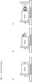
- FIGS 1a to 1c each show a schematic drawing of a conventional electrically excited synchronous machine (EESM).
- the electrically excited synchronous machine is arranged on a machine bed.
- a slip ring system has been used in most cases.
- contactless energy transfer systems CET
- CET contactless energy transfer systems
- this is usually attached laterally in the axial direction to the active part of the synchronous machine.
- the energy transfer system required for an EESM increases the installation space in the axial direction.
- Examples of the typical attachment of a contactless energy transfer system (CET) to an EESM are shown.
- a slip ring system can also be used.
- the abbreviation CET is therefore also intended to stand for a slip ring system.
- the Figures 1a to 1c The examples shown differ in the type of storage.
- the transmission system is Bearings of the synchronous machine are used, whereby the transmission system itself is not separately supported.
- the transmission system of Figure 1b is mounted on its own bearings and is therefore independent of the synchronous machine. In order to prevent the stator of the transmission system from rotating due to bearing friction, it is attached to the synchronous machine by means of a pin.
- a transmission system is shown which is mounted on its own bearings and is also separated from the synchronous machine by a coupling. Therefore, the transmission system must be mounted completely independently.
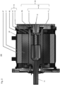
- the Figure 2 shows a schematic cross-sectional drawing (CAD drawing) of an electrically excited synchronous machine 100 according to a preferred embodiment of the present invention.
- the synchronous machine 100 comprises a synchronous machine rotor 10, a synchronous machine stator 40 and an excitation device 30.
- the synchronous machine 100 is designed as an internal rotor, ie the synchronous machine rotor 10 is spatially surrounded by the synchronous machine stator 40.
- the synchronous machine rotor 10 is arranged inside the synchronous machine 100, while the synchronous machine stator 40 is arranged outside the synchronous machine 100.
- the synchronous machine rotor 10 is arranged in a cavity of the synchronous machine stator 40.
- the synchronous machine rotor 10 has a synchronous machine rotor winding 15, which is also referred to as the excitation winding 15 due to its function within the electrically excited synchronous machine 100. Accordingly, the synchronous machine stator 40 has a synchronous machine stator winding 45.
- the excitation device 30 is used to electrically excite the synchronous machine 100 or the synchronous machine rotor 10 of the synchronous machine 100.
- the excitation device 30 comprises an energy transmission system 20 which is integrated in the synchronous machine rotor 10.
- the synchronous machine rotor 10 has a synchronous machine rotor shaft 13 and an excitation winding 15.
- the energy transmission system 20 of the excitation device 30 is arranged in a cavity of the synchronous machine rotor shaft 10.
- the energy transmission system 20 is designed in accordance with Figure 2 shown embodiment, a contactless or inductive energy transmission system.
- the energy transmission system 20 comprises or is a rotating energy transmission device.
- the energy transmission system 20 or the energy transmission device comprises an exciter stator 2 and an exciter rotor 4.
- the exciter rotor 4 spatially surrounds the exciter stator 2.
- the exciter stator is arranged inside the energy transmission system 20, while the exciter rotor is arranged outside the energy transmission system 20.
- the exciter stator 2 is arranged in a cavity of the exciter rotor 4.
- the energy transmission system 20 is thus designed as an external rotor.
- an alternating voltage generated by the energy transmission system 20 can be rectified in order to supply the excitation winding 15 of the synchronous machine rotor 10 with direct voltage or to feed direct current into the excitation winding 15 of the synchronous machine rotor 10 and thus generate a magnetic field.
- the synchronous machine rotor 10 further comprises a magnetic flux guide element 17.
- the synchronous machine stator 40 further comprises a magnetic flux guide element 47.
- the magnetic flux guide element 17 of the synchronous machine rotor 10 is arranged between the magnetic flux guide element 47 of the synchronous machine stator 40 and the synchronous machine rotor shaft 13.
- the magnetic flux guide element 17 serves to guide the magnetic flux on the synchronous machine rotor 10
- the magnetic flux guide element 47 serves to guide the magnetic flux on the synchronous machine stator 40.
- the exciter stator 2 is preferably made of a material that is both magnetically non-conductive and electrically non-conductive (in particular a plastic such as POM or PEEK). This is advantageously possible because the exciter stator 2 of the energy transmission system 20 no special stability requirements are imposed. It must only be possible to apply windings to the exciter stator 2. However, it is of course also possible to manufacture the exciter stator 2 from steel or aluminum. In this case, it is advantageous to apply an additional highly conductive electrical layer to the exciter stator 2.
- the exciter stator 2 has a bore along its longitudinal axis, which forms a cooling channel.
- the exciter stator 2 is hollow or tubular.
- a coolant such as air, water and/or oil can be let into the cooling channel via an inlet 12.
- the coolant can move through the cooling channel of the exciter stator 2 and thus effectively cool the exciter stator 2 from the inside.
- the synchronous machine rotor 10 is also cooled from the inside.
- the inlet 12 can also serve as an outlet for the coolant.
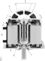
- the Figure 3 shows a schematic drawing of an electrically excited synchronous machine 100 according to another preferred embodiment of the present invention.
- the synchronous machine 100 of the Figure 3 a synchronous machine rotor 10, a synchronous machine stator 40 and an excitation device 30. Furthermore, a cover 50 of the synchronous machine 100 can also be seen.
- the excitation device 30 comprises the Figure 3 however, two energy transmission systems 20a and 20b, each of which is integrated in the synchronous machine rotor 10. Both energy transmission systems 20a and 20b are arranged in a cavity of the synchronous machine rotor shaft 13. Alternatively, for example, the second energy transmission system 20b could also be a data transmission system. It is understood that in general a plurality of energy transmission systems and/or a plurality of data transmission systems can also be integrated in the synchronous machine rotor 10 or in the cavity of the synchronous machine rotor shaft 13.
- a particular challenge in the design of the synchronous machine with integrated energy transmission system is the mechanical bearing of the non-drive side (right side in Figure 3 ) of the synchronous machine 100.
- a stationary element on which the bearing is mounted (such as the cover 50) preferably has one or more openings to enable the connection to the stationary part or to the exciter stator 2 of the energy transmission system 20 to be made, on the one hand, and to enable air circulation on the other hand, so that heat does not build up inside the rotor 10 or the rotor shaft 13 of the machine 100.
- the rotor shaft 13 also preferably has one or more openings for the passage of cables.
- the rotor shaft 13 may have one or more cooling openings for the passage of air and/or oil mist.
- the energy transmission system 20 comprises a primary side (stationary part or stator 2) and a secondary side (rotating part or rotor 4).
- the primary side of the energy transmission system 20 is arranged in extension of the rotation axis of the output shaft 13 of the synchronous machine 100 and is installed within the secondary side of the energy transmission system 20.
- the cable routing to the primary side can be through one or more openings of a (bearing) cover 50 of the non-output side (in the Figure 3 right).
- the primary-side electronics 6a for controlling the primary side is located in the Figures 7 to 9 This can be integrated outside the machine 100, in the power electronics of the machine 100 or in the casing of the machine 100.
- the windings are on the inside, followed by a magnetic flux guide (e.g. a deformable mat made of pressed ferrite composite) and a highly electrically conductive material (e.g. copper) for shielding radially outwards.
- the electronics 6b of the secondary side include in particular capacitors for reactive power compensation and a rectifier.
- the rectifier can be a passive full-bridge rectifier, an active half-bridge rectifier or a hybrid (comprising an active transistor and a passive diode per branch). Since the electronic components are the most thermally sensitive components, a circuit board containing the electronic components is preferably attached to the edge of the machine rotor 10.
- the secondary-side electronic device or circuit board 6b can be cooled by natural or forced convection.
- the secondary-side electronic device 6b can be thermally decoupled from the synchronous machine rotor shaft 13 by materials with poor thermal conductivity (e.g. plastic such as POM or PEEK), since in electrical machines this typically has temperatures that are unacceptable for the components.
- the connection from the secondary side to the secondary-side electronics is preferably made by means of feedthroughs or openings in the synchronous machine rotor shaft 13.
- Additional cooling openings offer the possibility of an air flow within the energy transmission system 20, so that the heat does not build up within the synchronous machine rotor 10 or the synchronous machine rotor shaft 13.
- an additional heat sink in particular in the form of a ring, is attached to the secondary-side electronic device 6b. This heat sink is preferably insulated from the rotor shaft 13 by poorly conductive or thermally insulating materials.
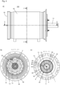
- the Figure 4a shows a side view of an electrically excited synchronous machine 100 with a synchronous machine rotor shaft 13, a synchronous machine stator 40 and a cover 50 according to a preferred embodiment of the present invention.
- the cover 50 preferably has openings (in the Figure 4a not visible), which serve to dissipate heat or to cool the synchronous machine 100.
- the dashed lines GG and JJ indicate cutting planes, which in the following Figures 4b to 5b be illustrated.
- the Figure 4b shows a schematic sectional drawing JJ of the electrically excited synchronous machine 100 of Figure 4a .
- grooves 42 in the synchronous machine stator 40 and individual poles of the synchronous machine rotor 10 can be seen.
- the rotor shaft 13 and the rotor winding 15 of the synchronous machine (excitation winding) can also be seen.
- Inside the rotor shaft 13 there is at least one energy transmitter 20, with an excitation stator 2 of the energy transmitter 20 being arranged in the center of the energy transmitter 20.
- the Figure 4c shows an enlargement of section K of Figure 4b .
- the at least one energy transmission system 20 arranged within the synchronous machine rotor shaft 13 has the following components from outside to inside: an additional electrically highly conductive layer 8 (in particular a copper layer), an adhesive 60, a plastic holder 62 with an integrated flux-conducting material (in particular a flux-conducting composite) and a recess 64 for the return of the excitation rotor winding 3, an adhesive 60, the excitation rotor winding 3, an air gap 22, a plastic sleeve 66, an adhesive 60, a bandage 68, the excitation stator winding 1, and the excitation stator 2 with a return element 70 for the return of the excitation stator winding 1.
- an additional electrically highly conductive layer 8 in particular a copper layer
- an adhesive 60 a plastic holder 62 with an integrated flux-conducting material (in particular a flux-conducting composite) and a recess 64 for the return of the excitation
- a cooling channel 5 (in particular a water channel) for actively cooling the stator 2 of the energy transmission system 20 can be seen. If two layers (back and forth) are wound, the return element 70 can be dispensed with. In this case, the cooling channel 5 can be made correspondingly larger,
- the Figure 5a shows a schematic sectional drawing GG of the electrically excited synchronous machine 100 of Figure 4a .
- the synchronous machine 100 has in particular a rotor winding 15, a laminated core 11 of the synchronous machine rotor and a synchronous machine stator 40 with a stator winding 45.
- the laminated core 11 is separated or spaced from the stator winding 45 by an air gap 16.
- the Figure 5b shows an enlarged view of section H of Figure 5a
- the Figure 5b a schematic sectional drawing of an exemplary excitation device 30, which comprises two energy transmission systems 20a and 20b. Both energy transmission systems 20a and 20b are arranged in a cavity of the synchronous machine rotor shaft 13.
- the energy transmission systems 20a and 20b have a common exciter stator 2 and a common exciter rotor 3 (or a common carrier on which all the exciter rotors, in this example two, are mounted).
- the common exciter rotor 3 (or the common carrier of the exciter rotors) is mechanically or rotationally fixedly connected to the synchronous machine rotor shaft 13.
- the first energy transmission system 20a has a first stator winding 1a and a first rotor winding 3a.
- the second energy transmission system 20b has a second stator winding 1b and a second rotor winding 3b.
- the first and second stator windings 1a and 1b are electrically separated from one another.
- the first and second rotor windings 3a and 3b are also electrically separated from one another.
- the secondary-side electronic device 6b of the excitation device 30 is preferably designed to control or monitor all energy transmission systems, in the example shown here the first energy transmission system 20a and the second energy transmission system 20a, as well as any existing data transmission systems.
- the secondary-side electronic device 6b is arranged on the synchronous machine rotor shaft 13, but outside the cavity of the synchronous machine rotor shaft 13 (in which the energy transmission systems 20a and 20b are located). In this way, the temperature in the cavity of the synchronous machine rotor shaft 13 can be kept as low as possible.
- the synchronous machine rotor shaft 13 has a cable feedthrough from the cavity of the synchronous machine rotor shaft 13 to the outside.
- an additional electrically conductive material layer 8 (in particular made of copper) at various points of the arrangement according to the invention or of the synchronous machine 100 according to the invention, in particular in the area of the excitation device 30, such as on at least one active part of the energy transmission system 20a or 20b.
- An active part of the energy transmission system is understood to be a part of the energy transmission system which is at least partially exposed to a magnetic field used for energy transmission.
- the electrical conductivity of the additional material layer 8 is greater than the electrical conductivity of the at least one active part. If the excitation stator 2 is made of steel, it is advantageous to arrange such an additional electrically conductive material layer 8, for example on the excitation stator 2.
- an additional electrically conductive material layer 8 can also be arranged on the excitation rotor 4 (see the Figures 2 , 3 and 6 ) and/or on magnetic flux-conducting elements or magnetic flux-conducting materials 7 of the synchronous machine 100 or the energy transmission system 20a, 20b. As in the Figures 5a and 5b As can be seen, the additional electrically conductive material layer 8 lines the entire cavity of the synchronous machine rotor shaft 13.
- the electrically excited synchronous machine 100 can also have an inlet and/or outlet 12 for a coolant (eg water), which is connected to a cooling channel 5 of the exciter stator 2.
- a coolant eg water
- the exciter stator 2 can thus be actively cooled from the inside.
- the synchronous machine rotor shaft 13 has several openings or air holes 14 for cooling the excitation device 30 or the energy transmission systems 20a and 20b with air.
- a bearing of the excitation device 30 in the synchronous machine rotor shaft 13 with the help of bearings 18 and 19 can be seen.
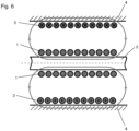
- the Figure 6 shows a schematic drawing of the principle of an inductive energy transmission path 20 integrated or integrable into the synchronous machine rotor or a synchronous machine rotor hollow shaft 13.
- Figure 6 an exemplary winding arrangement of stator winding 1 and rotor winding 3 of the energy transmission system 20 for generating a magnetic field used for energy transmission.
- the winding pattern is basically freely selectable.
- a particularly advantageous embodiment for a thin, elongated installation space, such as that found inside a rotor, is shown.
- the closed lines with the arrows indicate the magnetic flux.
- the Figure 7 shows a schematic drawing of an electrically excited machine 100 with a circuit according to a preferred embodiment of the present invention.
- the electrically excited machine 100 comprises a machine stator 40 with a stator winding 45 or stator windings 45a, 45b and 45c, and a machine rotor 10 with a rotor winding 15.
- An energy transmission system 20 or a coil system 28 of the energy transmission system 20 is arranged in the machine rotor 10 or in a cavity of the machine rotor 10.
- the energy transmission system 20 together with an inverter 24, an optional primary-side reactive power compensation circuit 25, a rectifier 26 and an optional secondary-side reactive power compensation circuit 27 form an excitation device 30 for electrically exciting the machine 100.
- the inverter 24 together with the optional primary-side reactive power compensation circuit 25 form a primary-side electronic device 6a.
- the rectifier 26, preferably an active rectifier, is connected to the rotor winding 15 of the machine 100 so that the rotor winding 15 can be supplied with a direct voltage or a direct current.
- the inverter 24 (single-phase), preferably a Full-bridge inverter, is connected to a battery 54.
- the battery 54 serves as an energy source and/or as an energy storage device.
- the battery 54 is also connected to a converter 52 for controlling the electrically excited machine 100, for example a 3-phase converter.
- the converter 52 is also connected to the stator winding 45 or the stator windings 45a, 45b and 45c of the machine 100.
- the inverter 24 can be combined with a primary-side compensation circuit 25 for the energy transmission system 20.
- the rectifier 26 can be combined with a secondary-side compensation circuit 27 for the energy transmission system 20.
- the inverter or converter 52 for the electrically excited machine 100 can be operated with an operating frequency A, while the inverter 26 for the energy transmission system 20 can be operated with an operating frequency B.
- the operating frequencies A and B can differ, which is usually the case.
- the operating frequency of the inverter 26 for the energy transmission system 20 is thus independent of the speed of the machine 100.
- the arrangement according to the invention is therefore used in particular for the rotor excitation of an electrical machine 100 in order to build up a static magnetic field and thus cause the machine rotor 10 to rotate.
- all four quadrants of an electrical machine can be started as a motor and generator without external forces.
- four-quadrant operation is possible with the arrangement described here.
- the electrical machine 100 which is excited with the aid of the excitation device 30, can therefore be used in particular both as a motor and as a generator.
- the coil system 28 is preferably single-phase and its operating frequency is independent of the speed of the machine 100.
- the Figure 8 shows an equivalent circuit diagram of an excitation device 30 according to a preferred embodiment of the present invention.
- the excitation device 30 comprises an energy transmission system with a coil system 28, wherein one coil of the coil system 28 belongs to a stationary primary side or a stationary primary system 2 of the excitation device 30 and another coil of the coil system 28 belongs to a rotatable primary side or a rotatable secondary system 4 of the excitation device 30.
- the primary system 2 comprises a voltage source 54, an inverter 24 and a primary-side compensation unit 25.
- the secondary system 2 comprises a secondary-side compensation unit 27 and a rectifier 26. In the embodiment shown, the inverter 24 and the primary-side compensation unit 25 form the primary-side electronic device 6a.
- the energy or voltage source 54 can also be part of the primary-side electronic device 6a.
- the secondary-side compensation unit 27 and the rectifier 26 form the secondary-side electronic device 6b.
- the rectifier 26 is connected to the rotor winding or rotor coil 15 of the electrically excited machine 100.
- the rotating energy transmission system 20, of which the coil system 28 is located in the cavity of the machine rotor 10 has the Figure 8 shown, electrically single-phase, structure.
- the coil system 28 is located within the cavity of the machine 100 or the machine rotor 10.
- the compensation unit can be arranged together with the inverter or rectifier on a circuit board.
- the circuit board of the rectifier 26 is preferably arranged outside the cavity of the machine rotor 10. Preferably, it is an active version of the rectifier 26.
- the compensation can be carried out in different forms.
- the Figure 9 shows various exemplary circuits for a primary-side compensation of the coil system 28.
- Figure 9a a serial circuit
- Figure 9b a parallel circuit
- Figure 9c an uncompensated circuit
- Figure 9d an LC circuit
- Figure 9e an LCC circuit.
- a resonant circuit is used for the excitation device or the energy transmission system, which is compensated in series on the primary side and in parallel on the secondary side.
- the circuit can be in series on the primary side and uncompensated on the secondary side.
- the circuit can be non-resonant and uncompensated on both sides.
- the present invention provides in particular a new solution for the construction of an electrically excited synchronous machine, wherein the electrical energy transfer to the rotor is preferably carried out without contact.
- the energy transfer system is integrated into the hollow rotor shaft of the electrical machine.
- the hollow shaft of the machine rotor can also be lined with a highly electrically conductive material in order to minimize losses when using an inductively contactless transmission system, in particular in the high frequency range.
- the transmission system is advantageously wear-free and a motor can take up less installation space (especially in the axial area).
- the electrically excited synchronous machine described in the context of the present invention offers greater reliability and less heat generation compared to conventional electrically excited synchronous machines, without the power density suffering as a result.
- One possible application of the present invention is, for example, in the field of electromobility.
Landscapes
- Engineering & Computer Science (AREA)
- Power Engineering (AREA)
- Computer Networks & Wireless Communication (AREA)
- Physics & Mathematics (AREA)
- Electromagnetism (AREA)
- Synchronous Machinery (AREA)
- Dynamo-Electric Clutches, Dynamo-Electric Brakes (AREA)
- Iron Core Of Rotating Electric Machines (AREA)
- Electric Propulsion And Braking For Vehicles (AREA)
- Connection Of Motors, Electrical Generators, Mechanical Devices, And The Like (AREA)
Applications Claiming Priority (3)
| Application Number | Priority Date | Filing Date | Title |
|---|---|---|---|
| DE102019004370 | 2019-06-19 | ||
| DE102020207000.8A DE102020207000B4 (de) | 2019-06-19 | 2020-06-04 | Elektrisch erregte Maschine und Anordnung für eine elektrisch erregte Maschine |
| EP21177864.2A EP3920385B1 (fr) | 2019-06-19 | 2021-06-04 | Machine à excitation électrique et agencement pour une machine à excitation électrique |
Related Parent Applications (2)
| Application Number | Title | Priority Date | Filing Date |
|---|---|---|---|
| EP21177864.2A Division-Into EP3920385B1 (fr) | 2019-06-19 | 2021-06-04 | Machine à excitation électrique et agencement pour une machine à excitation électrique |
| EP21177864.2A Division EP3920385B1 (fr) | 2019-06-19 | 2021-06-04 | Machine à excitation électrique et agencement pour une machine à excitation électrique |
Publications (2)
| Publication Number | Publication Date |
|---|---|
| EP4429074A2 true EP4429074A2 (fr) | 2024-09-11 |
| EP4429074A3 EP4429074A3 (fr) | 2024-12-11 |
Family
ID=73654099
Family Applications (3)
| Application Number | Title | Priority Date | Filing Date |
|---|---|---|---|
| EP21177864.2A Active EP3920385B1 (fr) | 2019-06-19 | 2021-06-04 | Machine à excitation électrique et agencement pour une machine à excitation électrique |
| EP21177858.4A Active EP3920372B1 (fr) | 2019-06-19 | 2021-06-04 | Procédé d'augmentation de l'efficacité d'un dispositif de transfert d'énergie, dispositif de transfert d'énergie et utilisation d'une matière électroconductrice |
| EP24177412.4A Pending EP4429074A3 (fr) | 2019-06-19 | 2021-06-04 | Machine à excitation électrique et agencement pour une machine à excitation électrique |
Family Applications Before (2)
| Application Number | Title | Priority Date | Filing Date |
|---|---|---|---|
| EP21177864.2A Active EP3920385B1 (fr) | 2019-06-19 | 2021-06-04 | Machine à excitation électrique et agencement pour une machine à excitation électrique |
| EP21177858.4A Active EP3920372B1 (fr) | 2019-06-19 | 2021-06-04 | Procédé d'augmentation de l'efficacité d'un dispositif de transfert d'énergie, dispositif de transfert d'énergie et utilisation d'une matière électroconductrice |
Country Status (3)
| Country | Link |
|---|---|
| US (3) | US11870307B2 (fr) |
| EP (3) | EP3920385B1 (fr) |
| DE (2) | DE102020207000B4 (fr) |
Families Citing this family (36)
| Publication number | Priority date | Publication date | Assignee | Title |
|---|---|---|---|---|
| DE102020207000B4 (de) | 2019-06-19 | 2023-02-23 | Universität Stuttgart, Körperschaft Des Öffentlichen Rechts | Elektrisch erregte Maschine und Anordnung für eine elektrisch erregte Maschine |
| DE102021210710A1 (de) | 2021-09-24 | 2023-03-30 | Mahle International Gmbh | Fremderregte elektrische Maschine |
| CN114665682B (zh) | 2020-12-22 | 2024-07-02 | 马勒国际有限公司 | 他励电机 |
| DE102021113453B4 (de) * | 2021-05-25 | 2023-09-28 | Eberhard Landau | Elektromotor |
| DE102021212012B3 (de) * | 2021-10-25 | 2023-04-06 | Mahle International Gmbh | Rotor für eine fremderregte Synchronmaschine |
| DE102021212549A1 (de) * | 2021-11-08 | 2023-05-11 | Mahle International Gmbh | Transformatoreinrichtung und Synchronmaschine |
| KR102684789B1 (ko) * | 2022-01-27 | 2024-07-11 | 이주열 | 비접촉식 회전 변압기 및 이를 포함하는 모터 |
| DE102022201589A1 (de) * | 2022-02-16 | 2023-08-17 | Zf Friedrichshafen Ag | Rotoranordnung für eine fremderregte Synchronmaschine |
| DE102022207340B3 (de) * | 2022-07-19 | 2024-01-25 | Zf Friedrichshafen Ag | Rotoranordnung für eine fremderregte Synchronmaschine |
| DE102022208028A1 (de) | 2022-08-03 | 2024-02-08 | Robert Bosch Gesellschaft mit beschränkter Haftung | Elektrische Maschine |
| DE102022124446A1 (de) * | 2022-09-23 | 2024-03-28 | Schaeffler Technologies AG & Co. KG | Kontaktlose Energieübertragungsvorrichtung, Kit-of-parts zur Herstellung einer kontaktlosen Energieübertragungsvorrichtung, Rotor einer elektrischen Maschine und elektrische Maschine sowie Verfahren zur Montage eines Rotors |
| DE102022124445A1 (de) * | 2022-09-23 | 2024-03-28 | Schaeffler Technologies AG & Co. KG | Kontaktlose Energieübertragungsvorrichtung, Verfahren zur Montage eines Rotors einer elektrischen Maschine, Rotor einer elektrischen Maschine und elektrische Maschine |
| DE102022124447A1 (de) * | 2022-09-23 | 2024-03-28 | Schaeffler Technologies AG & Co. KG | Kontaktlose Energieübertragungsvorrichtung, Kit-of-parts zur Herstellung einer kontaktlosen Energieübertragungsvorrichtung, Rotor einer elektrischen Maschine und elektrische Maschine sowie Verfahren zur Montage eines Rotors |
| DE102023203108A1 (de) * | 2023-04-04 | 2024-10-10 | Zf Friedrichshafen Ag | Rotorelement für einen Rotor einer elektrischen Maschine, Rotor und Verfahren zum Herstellen des Rotors |
| DE102023203358A1 (de) * | 2023-04-13 | 2024-10-17 | Zf Friedrichshafen Ag | Elektrische Antriebsachse für ein elektrisch angetriebenes Fahrzeug |
| DE102023203360A1 (de) * | 2023-04-13 | 2024-10-17 | Zf Friedrichshafen Ag | Antriebsachse für ein elektrisches Fahrzeug |
| DE102023203357A1 (de) * | 2023-04-13 | 2024-10-17 | Zf Friedrichshafen Ag | Elektrische Antriebsachse für ein elektrisch angetriebenes Fahrzeug |
| DE102023203491A1 (de) | 2023-04-18 | 2024-10-24 | Mahle International Gmbh | Rotor für eine fremderregte Synchronmaschine |
| DE102023203680A1 (de) * | 2023-04-21 | 2024-10-24 | Zf Friedrichshafen Ag | Elektrische Maschine mit einer fluidgekühlten Leistungsübertragungsvorrichtung sowie Fahrzeug mit der elektrischen Maschine |
| DE102023203683A1 (de) * | 2023-04-21 | 2024-10-24 | Zf Friedrichshafen Ag | Elektrische Maschine mit einer abgestützten Fluidlanze sowie Fahrzeug mit der elektrischen Maschine |
| EP4456387A1 (fr) * | 2023-04-24 | 2024-10-30 | Polestar Performance AB | Rotor, moteur électrique et véhicule électrique |
| DE102023207571A1 (de) * | 2023-08-07 | 2025-02-13 | Robert Bosch Gesellschaft mit beschränkter Haftung | Energieübertragersystem zur kontaktlosen Übertragung von elektrischer Energie in eine Erregerwicklung eines Rotors |
| DE102023124559A1 (de) | 2023-09-12 | 2025-03-13 | Universität Stuttgart (Körperschaft Des Öffentlichen Rechts) | Anordnung für eine elektrisch erregte Maschine |
| DE102023126454A1 (de) | 2023-09-28 | 2025-04-03 | Universität Stuttgart, Körperschaft Des Öffentlichen Rechts | Elektrische Leitung, Spule und induktive Energieübertragungsvorrichtung |
| EP4539312A1 (fr) * | 2023-10-11 | 2025-04-16 | Polestar Performance AB | Agencement à double excitation |
| WO2025105106A1 (fr) * | 2023-11-15 | 2025-05-22 | 株式会社アイシン | Dispositif d'entraînement de véhicule |
| DE102024200421A1 (de) * | 2024-01-17 | 2025-07-17 | Zf Friedrichshafen Ag | Leistungsübertragungsanordnung zur Leistungsübertragung auf eine Rotoranordnung einer fremderregten elektrischen Maschine, Rotoranordnung mit der Leistungsübertragungsanordnung sowie fremderregte elektrische Maschine mit der Rotoranordnung |
| DE102024201033A1 (de) * | 2024-02-06 | 2025-08-07 | Zf Friedrichshafen Ag | Leistungsübertragungsanordnung zur Leistungsübertragung auf eine Rotoranordnung einer fremderregten elektrischen Maschine, Verfahren zur Montage einer Leistungsübertragungsanordnung, Rotoranordnung mit der Leistungsübertragungsanordnung sowie fremderregte elektrische Maschine mit der Rotoranordnung |
| EP4604368A1 (fr) * | 2024-02-13 | 2025-08-20 | Polestar Performance AB | Rotor pour moteur électrique |
| DE102024202598B4 (de) * | 2024-03-19 | 2025-10-16 | Zf Friedrichshafen Ag | Rotoranordnung für eine fremderregte Synchronmaschine und fremderregte Synchronmaschine |
| DE102024203702B3 (de) * | 2024-04-22 | 2025-09-18 | Zf Friedrichshafen Ag | Rotorwelle mit integriertem Erreger, Rotorerdung und Rotorlagesensor |
| DE102024111680A1 (de) | 2024-04-25 | 2025-10-30 | Bayerische Motoren Werke Aktiengesellschaft | Rotorwelle mit integrierter, sekundärseitiger Kopplungseinrichtung einer induktiven Energieübertragungsvorrichtung |
| DE102024204441A1 (de) * | 2024-05-14 | 2025-11-20 | Contitech Vibration Control Gmbh | Gehäuseteil, vorzugsweise Motorgehäuseteil, zum zumindest abschnittsweisen Umschließen einer Vorrichtung, vorzugsweise eines Elektromotors |
| DE102024129543A1 (de) | 2024-10-11 | 2026-04-16 | Mahle International Gmbh | Befestigung eines Drehtransformators zur Bereitstellung eines DC-Erregerstroms für einen Rotor in einem extern erregten Synchronmotor |
| DE102024129483A1 (de) | 2024-10-11 | 2026-04-16 | Mahle International Gmbh | Elektrische Maschine |
| CN119891669B (zh) * | 2025-03-31 | 2025-06-27 | 常州锝莱电机有限公司 | 一种电机自动装配装置 |
Family Cites Families (31)
| Publication number | Priority date | Publication date | Assignee | Title |
|---|---|---|---|---|
| US3614593A (en) | 1970-05-06 | 1971-10-19 | Motorola Inc | Rotary transformer for alternator |
| DE2234472A1 (de) | 1972-07-13 | 1974-01-24 | Siemens Ag | Transformator mit relativ zueinander rotierenden koaxialen eisenkoerpern mit darin angeordneten ringspulen |
| DE7506469U (de) | 1975-01-17 | 1976-11-25 | Bbc Ag Brown, Boveri & Cie, Baden (Schweiz) | Messanordnung |
| US4647806A (en) | 1985-06-10 | 1987-03-03 | Giovanni Giuffrida | Brushless alternator |
| JPS6278072U (fr) | 1985-10-31 | 1987-05-19 | ||
| DE4333094A1 (de) | 1993-09-29 | 1995-03-30 | Abb Management Ag | Erregerstromleitung im Rotor einer elektrischen Maschine |
| US5519275A (en) | 1994-03-18 | 1996-05-21 | Coleman Powermate, Inc. | Electric machine with a transformer having a rotating component |
| DE19509264A1 (de) | 1995-03-15 | 1996-09-19 | Siemens Matsushita Components | Magnetischer und/oder magnetisierbarer Wickelträger |
| EP1042857A1 (fr) | 1998-07-30 | 2000-10-11 | Robert Bosch Gmbh | Moteur electrique, notamment alternateur triphase |
| GB2378586A (en) | 2001-07-31 | 2003-02-12 | Alstom | Rotor assembly with reduced heating due to eddy currents |
| DE10156212A1 (de) | 2001-11-15 | 2003-06-05 | Siemens Ag | Vorrichtung zur elektrischen Versorgung wenigstens eines Supraleiters |
| DE20204584U1 (de) | 2002-03-22 | 2003-08-14 | Walter Kraus GmbH, 86167 Augsburg | Übertrager für Windkraftanlage |
| US7412588B2 (en) | 2003-07-25 | 2008-08-12 | International Business Machines Corporation | Network processor system on chip with bridge coupling protocol converting multiprocessor macro core local bus to peripheral interfaces coupled system bus |
| US7230363B2 (en) | 2004-03-30 | 2007-06-12 | Honeywell International, Inc. | Low profile generator configuration |
| GB0422349D0 (en) | 2004-10-06 | 2004-11-10 | Zi Medical Plc | Electrical recharger unit |
| DE102004048961A1 (de) | 2004-10-07 | 2006-04-27 | Siemens Ag | Elektrische Maschine mit HTS-Läuferwicklung |
| DE102005047451A1 (de) | 2005-09-30 | 2007-04-12 | Siemens Ag | Synchronmaschine |
| US8052860B1 (en) * | 2007-04-26 | 2011-11-08 | The United States Of America As Represented By The Administrator Of The National Aeronautics And Space Administration | Electrochemical and mechanical polishing and shaping method and system |
| US20100295397A1 (en) * | 2009-05-20 | 2010-11-25 | Dowis William F | Electromechanical Machine |
| DE102011007247A1 (de) | 2011-04-13 | 2012-10-18 | Robert Bosch Gmbh | Wischblattadaptervorrichtung |
| SE537050C2 (sv) * | 2011-06-30 | 2014-12-16 | Atlas Copco Ind Tech Ab | Transformator innefattande en kontaktlös signalanslutning |
| ITTO20111113A1 (it) | 2011-12-05 | 2013-06-06 | Wilic Sarl | Impianto eolico per la generazione di energia elettrica |
| US9511855B2 (en) | 2014-01-22 | 2016-12-06 | Sikorsky Aircraft Corporation | Power and data transfer to hub sensors |
| US10305356B2 (en) | 2014-09-26 | 2019-05-28 | The Boeing Company | Synchronous machine with common motor/generator exciter stage |
| DE102016218819B4 (de) | 2016-09-29 | 2018-10-11 | Audi Ag | Kühlsystem |
| WO2018067148A1 (fr) * | 2016-10-05 | 2018-04-12 | Hewlett-Packard Development Company, L.P. | Substrat en alliage à revêtement extérieur |
| JP6945188B2 (ja) | 2016-11-30 | 2021-10-06 | パナソニックIpマネジメント株式会社 | 無線給電ユニット、送電モジュール、受電モジュールおよび無線電力伝送システム |
| DE102017214766B4 (de) | 2017-08-23 | 2023-02-02 | Vitesco Technologies GmbH | Elektrische Maschine mit einem Leistungsübertragungssystem zum Erzeugen eines Stroms in einer Erregerwicklung eines Rotors der elektrischen Maschine und Kraftfahrzeug |
| DE102020207000B4 (de) | 2019-06-19 | 2023-02-23 | Universität Stuttgart, Körperschaft Des Öffentlichen Rechts | Elektrisch erregte Maschine und Anordnung für eine elektrisch erregte Maschine |
| DE102019212406A1 (de) | 2019-08-20 | 2021-02-25 | Vitesco Technologies Germany Gmbh | Leistungsübertragungssystem zum Erzeugen eines Stroms in einer Erregerwicklung eines Rotors einer elektrischen Maschine sowie elektrische Maschine und Kraftfahrzeug |
| CN110635576A (zh) | 2019-11-12 | 2019-12-31 | 武汉理工大学 | 替代电励磁电机电刷滑环的旋转无线传能装置 |
-
2020
- 2020-06-04 DE DE102020207000.8A patent/DE102020207000B4/de active Active
- 2020-06-04 DE DE102020206998.0A patent/DE102020206998B4/de active Active
-
2021
- 2021-06-04 EP EP21177864.2A patent/EP3920385B1/fr active Active
- 2021-06-04 EP EP21177858.4A patent/EP3920372B1/fr active Active
- 2021-06-04 US US17/339,612 patent/US11870307B2/en active Active
- 2021-06-04 US US17/339,635 patent/US12166385B2/en active Active
- 2021-06-04 EP EP24177412.4A patent/EP4429074A3/fr active Pending
-
2024
- 2024-12-02 US US18/966,054 patent/US20250096651A1/en active Pending
Also Published As
| Publication number | Publication date |
|---|---|
| EP3920385B1 (fr) | 2024-07-31 |
| EP3920385C0 (fr) | 2024-07-31 |
| DE102020206998B4 (de) | 2023-02-23 |
| US11870307B2 (en) | 2024-01-09 |
| US20250096651A1 (en) | 2025-03-20 |
| EP3920372A1 (fr) | 2021-12-08 |
| DE102020207000B4 (de) | 2023-02-23 |
| US20210408875A1 (en) | 2021-12-30 |
| EP3920372B1 (fr) | 2023-10-11 |
| US12166385B2 (en) | 2024-12-10 |
| DE102020207000A1 (de) | 2020-12-24 |
| EP4429074A3 (fr) | 2024-12-11 |
| EP3920385A1 (fr) | 2021-12-08 |
| DE102020206998A1 (de) | 2020-12-24 |
| US20220060088A1 (en) | 2022-02-24 |
| EP3920372C0 (fr) | 2023-10-11 |
Similar Documents
| Publication | Publication Date | Title |
|---|---|---|
| EP3920385B1 (fr) | Machine à excitation électrique et agencement pour une machine à excitation électrique | |
| DE102017214766B4 (de) | Elektrische Maschine mit einem Leistungsübertragungssystem zum Erzeugen eines Stroms in einer Erregerwicklung eines Rotors der elektrischen Maschine und Kraftfahrzeug | |
| DE3923525C2 (de) | Computertomographie-(CT)-Scanner | |
| DE69310714T2 (de) | Elektromotorische leichtgewichtsvorrichtung von hoher leistung | |
| EP1481407B1 (fr) | Transformateur | |
| WO2023156396A1 (fr) | Agencement de rotor pour une machine synchrone à excitation séparée | |
| EP1938443B1 (fr) | Machine synchrone | |
| DE102016218741B4 (de) | Elektrische Maschine mit verbesserter Kühlung | |
| DE102021211992A1 (de) | Rotor für eine fremderregte Synchronmaschine | |
| EP2929622B1 (fr) | Machine asynchrone à répartition optimisée des pertes électriques entre le stator et le rotor | |
| DE3313747C2 (de) | Elektrische Maschine | |
| DE10147129A1 (de) | Hochspannungstransformatorwicklung und Verfahren zur Herstellung | |
| DE69221280T2 (de) | Röntgenröhre mit kapazitiv gekoppelter Glühwendelansteuerung | |
| WO2022136548A1 (fr) | Transformateur rotatif électrique destiné à la transmission inductive d'énergie | |
| WO2018024699A1 (fr) | Machine électrique à refroidissement plus efficace | |
| DE3629044A1 (de) | Statische erregervorrichtung fuer eine dynamoelektrische maschine | |
| EP4033859A1 (fr) | Générateur de chaleur tournante et à induction à excitation courant continu, à rendement électrique/cinétique extrêmement faible et à coefficient de performance thermique extrêmement élevé | |
| EP1725420B1 (fr) | Ensemble magnetique pour des systemes de portee, de guidage et/ou de freinage dans des vehicules a sustentation magnetique | |
| WO2023232487A1 (fr) | Transformateur rotatif électrique pour transmission d'énergie par induction | |
| EP2038983A1 (fr) | Machine synchrone avec paliers magnétiques excités par le rotor | |
| EP3672041A1 (fr) | Machine électrique à rotor à disque | |
| EP3211767B1 (fr) | Machine electrique comprenant un induit en cloche | |
| DE102023132921A1 (de) | Hybridrotor für synchronmaschine | |
| DE102023124559A1 (de) | Anordnung für eine elektrisch erregte Maschine | |
| DE102021100221A1 (de) | Stator |
Legal Events
| Date | Code | Title | Description |
|---|---|---|---|
| PUAI | Public reference made under article 153(3) epc to a published international application that has entered the european phase |
Free format text: ORIGINAL CODE: 0009012 |
|
| STAA | Information on the status of an ep patent application or granted ep patent |
Free format text: STATUS: REQUEST FOR EXAMINATION WAS MADE |
|
| 17P | Request for examination filed |
Effective date: 20240522 |
|
| AC | Divisional application: reference to earlier application |
Ref document number: 3920385 Country of ref document: EP Kind code of ref document: P |
|
| AK | Designated contracting states |
Kind code of ref document: A2 Designated state(s): AL AT BE BG CH CY CZ DE DK EE ES FI FR GB GR HR HU IE IS IT LI LT LU LV MC MK MT NL NO PL PT RO RS SE SI SK SM TR |
|
| REG | Reference to a national code |
Ref country code: DE Ref legal event code: R079 Free format text: PREVIOUS MAIN CLASS: H02J0050700000 Ipc: H02K0011042000 |
|
| PUAL | Search report despatched |
Free format text: ORIGINAL CODE: 0009013 |
|
| AK | Designated contracting states |
Kind code of ref document: A3 Designated state(s): AL AT BE BG CH CY CZ DE DK EE ES FI FR GB GR HR HU IE IS IT LI LT LU LV MC MK MT NL NO PL PT RO RS SE SI SK SM TR |
|
| RIC1 | Information provided on ipc code assigned before grant |
Ipc: H02J 50/70 20160101ALI20241105BHEP Ipc: H02J 50/00 20160101ALI20241105BHEP Ipc: H02J 50/10 20160101ALI20241105BHEP Ipc: H02K 11/01 20160101ALI20241105BHEP Ipc: H02K 19/36 20060101ALI20241105BHEP Ipc: H02K 19/12 20060101ALI20241105BHEP Ipc: H02K 11/042 20160101AFI20241105BHEP |