EP4429320A1 - Procédé de transmission/réception d'informations concernant une mesure prs dans un système de communication sans fil, et appareil associé - Google Patents
Procédé de transmission/réception d'informations concernant une mesure prs dans un système de communication sans fil, et appareil associé Download PDFInfo
- Publication number
- EP4429320A1 EP4429320A1 EP22890413.2A EP22890413A EP4429320A1 EP 4429320 A1 EP4429320 A1 EP 4429320A1 EP 22890413 A EP22890413 A EP 22890413A EP 4429320 A1 EP4429320 A1 EP 4429320A1
- Authority
- EP
- European Patent Office
- Prior art keywords
- prs
- information
- measurement
- path
- location
- Prior art date
- Legal status (The legal status is an assumption and is not a legal conclusion. Google has not performed a legal analysis and makes no representation as to the accuracy of the status listed.)
- Pending
Links
Images


Classifications
-
- H—ELECTRICITY
- H04—ELECTRIC COMMUNICATION TECHNIQUE
- H04W—WIRELESS COMMUNICATION NETWORKS
- H04W8/00—Network data management
- H04W8/22—Processing or transfer of terminal data, e.g. status or physical capabilities
- H04W8/24—Transfer of terminal data
-
- H—ELECTRICITY
- H04—ELECTRIC COMMUNICATION TECHNIQUE
- H04W—WIRELESS COMMUNICATION NETWORKS
- H04W64/00—Locating users or terminals or network equipment for network management purposes, e.g. mobility management
- H04W64/003—Locating users or terminals or network equipment for network management purposes, e.g. mobility management locating network equipment
-
- G—PHYSICS
- G01—MEASURING; TESTING
- G01S—RADIO DIRECTION-FINDING; RADIO NAVIGATION; DETERMINING DISTANCE OR VELOCITY BY USE OF RADIO WAVES; LOCATING OR PRESENCE-DETECTING BY USE OF THE REFLECTION OR RERADIATION OF RADIO WAVES; ANALOGOUS ARRANGEMENTS USING OTHER WAVES
- G01S5/00—Position-fixing by co-ordinating two or more direction or position line determinations; Position-fixing by co-ordinating two or more distance determinations
- G01S5/0009—Transmission of position information to remote stations
- G01S5/0018—Transmission from mobile station to base station
- G01S5/0036—Transmission from mobile station to base station of measured values, i.e. measurement on mobile and position calculation on base station
-
- G—PHYSICS
- G01—MEASURING; TESTING
- G01S—RADIO DIRECTION-FINDING; RADIO NAVIGATION; DETERMINING DISTANCE OR VELOCITY BY USE OF RADIO WAVES; LOCATING OR PRESENCE-DETECTING BY USE OF THE REFLECTION OR RERADIATION OF RADIO WAVES; ANALOGOUS ARRANGEMENTS USING OTHER WAVES
- G01S5/00—Position-fixing by co-ordinating two or more direction or position line determinations; Position-fixing by co-ordinating two or more distance determinations
- G01S5/02—Position-fixing by co-ordinating two or more direction or position line determinations; Position-fixing by co-ordinating two or more distance determinations using radio waves
- G01S5/0273—Position-fixing by co-ordinating two or more direction or position line determinations; Position-fixing by co-ordinating two or more distance determinations using radio waves using multipath or indirect path propagation signals in position determination
-
- H—ELECTRICITY
- H04—ELECTRIC COMMUNICATION TECHNIQUE
- H04B—TRANSMISSION
- H04B17/00—Monitoring; Testing
- H04B17/30—Monitoring; Testing of propagation channels
- H04B17/309—Measuring or estimating channel quality parameters
- H04B17/318—Received signal strength
- H04B17/328—Reference signal received power [RSRP]; Reference signal received quality [RSRQ]
-
- H—ELECTRICITY
- H04—ELECTRIC COMMUNICATION TECHNIQUE
- H04W—WIRELESS COMMUNICATION NETWORKS
- H04W24/00—Supervisory, monitoring or testing arrangements
- H04W24/10—Scheduling measurement reports ; Arrangements for measurement reports
-
- H—ELECTRICITY
- H04—ELECTRIC COMMUNICATION TECHNIQUE
- H04W—WIRELESS COMMUNICATION NETWORKS
- H04W64/00—Locating users or terminals or network equipment for network management purposes, e.g. mobility management
Definitions
- the present disclosure relates to a method of transmitting and receiving information for measurement of a PRS in a wireless communication system and a device therefor.
- Mobile communication systems have been developed to guarantee user activity while providing voice services.
- Mobile communication systems are expanding their services from voice only to data.
- Current soaring data traffic is depleting resources and users' demand for higher-data rate services is leading to the need for more advanced mobile communication systems.
- Next-generation mobile communication systems are required to meet, e.g., handling of explosively increasing data traffic, significant increase in per-user transmission rate, working with a great number of connecting devices, and support for very low end-to-end latency and high-energy efficiency.
- various research efforts are underway for various technologies, such as dual connectivity, massive multiple input multiple output (MIMO), in-band full duplex, non-orthogonal multiple access (NOMA), super wideband support, and device networking.
- MIMO massive multiple input multiple output
- NOMA non-orthogonal multiple access
- super wideband support and device networking.
- a value (e.g., DL PRS RSRP) reported for positioning is determined based on a linear average of received strengths for REs in which a PRS is transmitted.
- a signal path between a base station and a UE is line of sight (LoS) or non-line of sight (NLoS) is more important than a channel environment (i.e., a channel environment related to signal intensity).
- a channel environment i.e., a channel environment related to signal intensity
- it cannot be determined whether the path taken by the signal is the line of sight (LoS) or the non-line of sight (NLoS) through a magnitude of the RSRP.
- path-specific measurement values e.g., DL PRS RSRPP
- the UE may report measurement information per path related to the PRS.
- the following problems related to a path-specific measurement of a UE may occur.
- the unnecessary signaling overhead may increase.
- a location server e.g., LMF
- DL PRS RSRPP e.g., LPP message
- Reporting of path-specific measurement values may not contribute to improving positioning accuracy. This is described in detail below.
- path-specific measurement is supported by a specific UE, measurement values that do not contribute to the LoS/NLoS determination may be reported. In this case, reporting of the path-specific measurement values may increase the signaling overhead and may have little contribution to improving the positioning accuracy.
- An object of the present disclosure is to minimize an unnecessary signaling overhead in a report for PRS measurement of a UE.
- Another object of the present disclosure is to report realistic values in terms of positioning accuracy in a report for PRS measurement.
- a method of a user equipment (UE) for transmitting information on a measurement of a positioning reference signal (PRS) in a wireless communication system comprises transmitting, to a location server, a message including capability information, receiving the PRS from a base station, and transmitting, to the location server, a message including the information on the measurement of the PRS.
- the capability information includes information related to a positioning method supported by the UE.
- the information on the measurement of the PRS includes a DL PRS reference signal received path power (RSRPP) for one or more paths related to the PRS.
- RRPP DL PRS reference signal received path power
- the capability information includes i) information representing whether to support a measurement for a first path related to the PRS and/or ii) information representing whether to support a measurement for at least one additional path related to the PRS.
- the method may further comprise receiving, from the location server, a message including request information for the measurement of the PRS.
- the request information for the measurement of the PRS may include i) information indicating a provision of the measurement for the first path and/or ii) information indicating a provision of the measurement for the at least one additional path.
- the information on the measurement of the PRS may include i) timing information related to each path of the at least one additional path and ii) information representing a quality related to each path of the at least one additional path.
- the method may further comprise receiving, from the location server, a message including request information for the capability information.
- a DL PRS RSRPP related to the at least one additional path may be greater than a minimum threshold determined based on a DL PRS RSRPP related to the first path and a preset offset.
- the positioning method may be i) a downlink-time difference of arrival (DL-TDOA) positioning method or ii) a multi-round trip time (RTT) positioning method.
- DL-TDOA downlink-time difference of arrival
- RTT multi-round trip time
- the message including the capability information may be transmitted based on an LTE positioning protocol (LPP) procedure, and the message including the information on the measurement of the PRS may be transmitted based on the LPP procedure.
- LPP LTE positioning protocol
- the information representing whether to support the measurement for the at least one additional path related to the PRS may indicate a number of additional paths supported by the UE.
- the DL PRS RSRPP included in the information on the measurement of the PRS may be based on a DL PRS RSRPP with a value within a pre-defined range among DL PRS RSRPPs measured for the one or more paths related to the PRS.
- the pre-defined range may be determined based on an expected value related to the DL PRS RSRPP and range information related to the expected value.
- the method may further comprise receiving, from the location server, configuration information including the expected value related to the DL PRS RSRPP and the range information related to the expected value.
- a user equipment (UE) configured to transmit information on a measurement of a positioning reference signal (PRS) in a wireless communication system according to another embodiment of the present disclosure comprises one or more transceivers, one or more processors configured to control the one or more transceivers, and one or more memories operably connected to the one or more processors.
- PRS positioning reference signal
- the one or more memories are configured to store instructions performing operations based on being executed by the one or more processors.
- the operations comprise transmitting, to a location server, a message including capability information, receiving the PRS from a base station, and transmitting, to the location server, a message including the information on the measurement of the PRS.
- the capability information includes information related to a positioning method supported by the UE.
- the information on the measurement of the PRS includes a DL PRS reference signal received path power (RSRPP) for one or more paths related to the PRS.
- RRPP DL PRS reference signal received path power
- the capability information includes i) information representing whether to support a measurement for a first path related to the PRS and/or ii) information representing whether to support a measurement for at least one additional path related to the PRS.
- a device controlling a user equipment (UE) to transmit information on a measurement of a positioning reference signal (PRS) in a wireless communication system comprises one or more processors, and one or more memories operably connected to the one or more processors.
- the one or more memories are configured to store instructions performing operations based on being executed by the one or more processors.
- the operations comprise transmitting, to a location server, a message including capability information, receiving the PRS from a base station, and transmitting, to the location server, a message including the information on the measurement of the PRS.
- the capability information includes information related to a positioning method supported by the UE.
- the information on the measurement of the PRS includes a DL PRS reference signal received path power (RSRPP) for one or more paths related to the PRS.
- RRPP DL PRS reference signal received path power
- the capability information includes i) information representing whether to support a measurement for a first path related to the PRS and/or ii) information representing whether to support a measurement for at least one additional path related to the PRS.
- One or more non-transitory computer readable mediums store one or more instructions.
- the one or more instructions perform operations based on being executed by one or more processors.
- the operations comprise transmitting, to a location server, a message including capability information, receiving the PRS from a base station, and transmitting, to the location server, a message including the information on the measurement of the PRS.
- the capability information includes information related to a positioning method supported by the UE.
- the information on the measurement of the PRS includes a DL PRS reference signal received path power (RSRPP) for one or more paths related to the PRS.
- RRPP DL PRS reference signal received path power
- the capability information includes i) information representing whether to support a measurement for a first path related to the PRS and/or ii) information representing whether to support a measurement for at least one additional path related to the PRS.
- a method of a location server for receiving information on a measurement of a positioning reference signal (PRS) in a wireless communication system comprises receiving, from a user equipment (UE), a message including capability information, and receiving, from the UE, a message including the information on the measurement of the PRS.
- the capability information includes information related to a positioning method supported by the UE.
- the information on the measurement of the PRS includes a DL PRS reference signal received path power (RSRPP) for one or more paths related to the PRS.
- RRPP DL PRS reference signal received path power
- the capability information includes i) information representing whether to support a measurement for a first path related to the PRS and/or ii) information representing whether to support a measurement for at least one additional path related to the PRS.
- a location server receiving information on a measurement of a positioning reference signal (PRS) in a wireless communication system comprises one or more transceivers, one or more processors configured to control the one or more transceivers, and one or more memories operably connected to the one or more processors.
- PRS positioning reference signal
- the one or more memories are configured to store instructions performing operations based on being executed by the one or more processors.
- the operations comprise receiving, from a user equipment (UE), a message including capability information, and receiving, from the UE, a message including the information on the measurement of the PRS.
- the capability information includes information related to a positioning method supported by the UE.
- the information on the measurement of the PRS includes a DL PRS reference signal received path power (RSRPP) for one or more paths related to the PRS.
- RRPP DL PRS reference signal received path power
- the capability information includes i) information representing whether to support a measurement for a first path related to the PRS and/or ii) information representing whether to support a measurement for at least one additional path related to the PRS.
- a path specific measurement report is supported by a UE (e.g., whether to support a measurement for a first path of PRS) is reported to a location server.
- a reporting operation for path specific measurement information based on a request of the location server can be performed more efficiently in terms of signaling overhead.
- Whether to support additional paths in addition to the first path can be reported additionally. Therefore, a request for path specific measurement information based on a capability of each UE of UEs supporting a path specific measurement can be sub-divided and performed. That is, reporting of measurement information can be performed making full use of the capability of the UE.
- a value (e.g., value greater than a minimum threshold) determined by a preset threshold among measurement values (e.g., multiple DL PRS RSRPPs) for the additional path related to PRS is reported to the UE. Since meaningful values for LoS/NLoS determination can be reported, positioning accuracy can be improved. Based on the threshold, measurement values (that do not contribute to determining LoS/NLoS) can be excluded from reporting. Accordingly, the path-specific measurement reporting operation can be improved in terms of signaling overhead.
- known structures or devices may be omitted or be shown in block diagrams while focusing on core features of each structure and device.
- downlink means communication from a base station to a terminal
- uplink means communication from the terminal to the base station.
- a transmitter may be part of the base station, and a receiver may be part of the terminal.
- the transmitter may be part of the terminal and the receiver may be part of the base station.
- the base station may be expressed as a first communication device and the terminal may be expressed as a second communication device.
- a base station may be replaced with terms including a fixed station, a Node B, an evolved-NodeB (eNB), a Next Generation NodeB (gNB), a base transceiver system (BTS), an access point (AP), a network (5G network), an AI system, a road side unit (RSU), a vehicle, a robot, an Unmanned Aerial Vehicle (UAV), an Augmented Reality (AR) device, a Virtual Reality (VR) device, and the like.
- a fixed station a Node B, an evolved-NodeB (eNB), a Next Generation NodeB (gNB), a base transceiver system (BTS), an access point (AP), a network (5G network), an AI system, a road side unit (RSU), a vehicle, a robot, an Unmanned Aerial Vehicle (UAV), an Augmented Reality (AR) device, a Virtual Reality (VR) device, and the like.
- the terminal may be fixed or mobile and may be replaced with terms including a User Equipment (UE), a Mobile Station (MS), a user terminal (UT), a Mobile Subscriber Station (MSS), a Subscriber Station (SS), an Advanced Mobile Station (AMS), a Wireless Terminal (WT), a Machine-Type Communication (MTC) device, a Machine-to-Machine (M2M) device, and a Device-to-Device (D2D) device, the vehicle, the robot, an AI module, the Unmanned Aerial Vehicle (UAV), the Augmented Reality (AR) device, the Virtual Reality (VR) device, and the like.
- UAV Unmanned Aerial Vehicle
- AR Augmented Reality
- VR Virtual Reality
- the following technology may be used in various wireless access systems, such as code division multiple access (CDMA), frequency division multiple access (FDMA), time division multiple access (TDMA), orthogonal frequency division multiple access (OFDMA), single carrier-FDMA (SC-FDMA), non-orthogonal multiple access (NOMA), and the like.
- CDMA may be implemented by radio technology such as universal terrestrial radio access (UTRA) or CDMA2000.
- UTRA universal terrestrial radio access
- TDMA may be implemented by radio technology such as global system for mobile communications (GSM)/general packet radio service (GPRS)/enhanced data rates for GSM evolution (EDGE).
- GSM global system for mobile communications
- GPRS general packet radio service
- EDGE enhanced data rates for GSM evolution
- the OFDMA may be implemented as radio technology such as IEEE 802.11(Wi-Fi), IEEE 802.16 (WiMAX), IEEE 802-20, E-UTRA (evolved UTRA), and the like.
- the UTRA is a part of a universal mobile telecommunication system (UMTS).
- LTE-A evolution of 3GPP LTE.
- LTE means technology after 3GPP TS 36.xxx Release 8.
- LTE technology after 3GPP TS 36.xxx Release 10 is referred to as the LTE-A
- LTE technology after 3GPP TS 36.xxx Release 13 is referred to as the LTE-A pro.
- the 3GPP NR means technology after TS 38.xxx Release 15.
- the LTE/NR may be referred to as a 3GPP system.
- "xxx" means a standard document detail number.
- next-generation radio access technology considering enhanced mobile broadband communication (eMBB), massive MTC (mMTC), ultra-reliable and low latency communication (URLLC) is discussed, and in the present disclosure, the technology is called NR for convenience.
- eMBB enhanced mobile broadband communication
- mMTC massive MTC
- URLLC ultra-reliable and low latency communication
- NR is an expression representing an example of 5G radio access technology
- a New RAT system including NR uses an OFDM transmission scheme or a similar transmission scheme thereto.
- the new RAT system may follow OFDM parameters different from OFDM parameters of LTE.
- the new RAT system may follow numerology of conventional LTE/LTE-A as it is or have a larger system bandwidth (e.g., 100 MHz).
- one cell may support a plurality of numerologies. In other words, UEs that operate with different numerologies may coexist in one cell.
- the numerology corresponds to one subcarrier spacing in a frequency domain. By scaling a reference subcarrier spacing by an integer N, different numerologies may be defined.
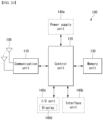
- FIG. 1 illustrates an example overall NR system structure to which a method as proposed in the disclosure may apply.
- an NG-RAN is constituted of gNBs to provide a control plane (RRC) protocol end for user equipment (UE) and NG-RA user plane (new AS sublayer/PDCP/RLC/MAC/PHY).
- RRC control plane
- UE user equipment
- NG-RA user plane new AS sublayer/PDCP/RLC/MAC/PHY
- the gNBs are mutually connected via an Xn interface.
- the gNBs are connected to the NGC via the NG interface.
- the gNB connects to the access and mobility management function (AMF) via the N2 interface and connects to the user plane function (UPF) via the N3 interface.
- AMF access and mobility management function
- UPF user plane function
- the numerology may be defined by the subcarrier spacing and cyclic prefix (CP) overhead.
- CP cyclic prefix
- multiple subcarrier spacings may be derived by scaling the basic subcarrier spacing by integer N (or, ⁇ ).
- N integer
- the numerology used may be selected independently from the frequency band.
- OFDM orthogonal frequency division multiplexing
- NR supports multiple numerologies (or subcarrier spacings (SCS)) for supporting various 5G services. For example, if SCS is 15 kHz, NR supports a wide area in typical cellular bands. If SCS is 30 kHz/60 kHz, NR supports a dense urban, lower latency and a wider carrier bandwidth. If SCS is 60 kHz or higher, NR supports a bandwidth greater than 24.25 GHz in order to overcome phase noise.
- numerologies or subcarrier spacings (SCS)
- An NR frequency band is defined as a frequency range of two types FR1 and FR2.
- the FR1 and the FR2 may be configured as in Table 1 below. Furthermore, the FR2 may mean a millimeter wave (mmW).
- mmW millimeter wave
- one set of frames for uplink and one set of frames for downlink may exist.
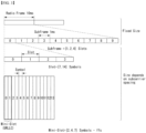
- FIG. 2 illustrates a relationship between an uplink frame and downlink frame in a wireless communication system to which a method described in the present disclosure is applicable.
- slots are numbered in ascending order of n s ⁇ ⁇ 0 , ... , N subframe slots , ⁇ ⁇ 1 in the subframe and in ascending order of n s ,f ⁇ ⁇ 0 , ... , N frame slots , ⁇ ⁇ 1 in the radio frame.
- One slot includes consecutive OFDM symbols of N symb ⁇ , and N symb ⁇ is determined according to the used numerology and slot configuration.
- the start of slot n s ⁇ is temporally aligned with the start of n s ⁇ N symb ⁇ .
- Not all UEs are able to transmit and receive at the same time, and this means that not all OFDM symbols in a downlink slot or an uplink slot are available to be used.
- Table 3 represents the number N symb slot of OFDM symbols per slot, the number N slot frame , ⁇ of slots per radio frame, and the number N slot subframe , ⁇ of slots per subframe in a normal CP.
- Table 4 represents the number of OFDM symbols per slot, the number of slots per radio frame, and the number of slots per subframe in an extended CP. [Table 3] ⁇ N symb slot N slot frame , ⁇ N slot subframe , ⁇ 0 14 10 1 1 14 20 2 2 14 40 4 3 14 80 8 4 14 160 16 [Table 4] ⁇ N symb slot N slot frame , ⁇ N slot subframe , ⁇ 2 12 40 4
- FIG. 3 illustrates an example of a frame structure in a NR system.
- FIG. 3 is merely for convenience of explanation and does not limit the scope of the present disclosure.
- a mini-slot may consist of 2, 4, or 7 symbols, or may consist of more symbols or less symbols.
- an antenna port In regard to physical resources in the NR system, an antenna port, a resource grid, a resource element, a resource block, a carrier part, etc. May be considered.
- the antenna port is defined so that a channel over which a symbol on an antenna port is conveyed may be inferred from a channel over which another symbol on the same antenna port is conveyed.
- the two antenna ports may be regarded as being in a quasi co-located or quasi co-location (QC/QCL) relation.
- the large-scale properties may include at least one of delay spread, Doppler spread, frequency shift, average received power, and received timing.
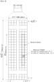
- FIG. 4 illustrates an example of a resource grid supported in a wireless communication system to which a method proposed in the present disclosure is applicable.
- a resource grid consists of N RB ⁇ N sc RB subcarriers on a frequency domain, each subframe consisting of 14 ⁇ 2 ⁇ OFDM symbols, but the present disclosure is not limited thereto.
- a transmitted signal is described by one or more resource grids, consisting of N RB ⁇ N sc RB subcarriers, and 2 ⁇ N symb ⁇ OFDM symbols, where N RB ⁇ ⁇ N RB max , ⁇ . N RB max , ⁇ denotes a maximum transmission bandwidth and may change not only between numerologies but also between uplink and downlink.
- one resource grid may be configured per numerology ⁇ and antenna port p.
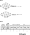
- FIG. 5 illustrates examples of a resource grid per antenna port and numerology to which a method proposed in the present disclosure is applicable.
- the resource element (k,l ⁇ ) for the numerology ⁇ and the antenna port p corresponds to a complex value a k , l ⁇ p ⁇ .
- the indexes p and ⁇ may be dropped, and as a result, the complex value may be a k , l ⁇ p or a k , l ⁇ .
- Point A serves as a common reference point of a resource block grid and may be obtained as follows.
- the common resource blocks are numbered from 0 and upwards in the frequency domain for subcarrier spacing configuration ⁇ .
- n CRB ⁇ ⁇ k N sc RB ⁇
- Physical resource blocks are defined within a bandwidth part (BWP) and are numbered from 0 to N BWP , i size ⁇ 1 , where i is No. Of the BWP.
- BWP bandwidth part
- n PRB in BWP i the common resource block
- n CRB n PRB + N BWP , i start
- N BWP , i start may be the common resource block where the BWP starts relative to the common resource block 0.
- FIG. 6 illustrates physical channels and general signal transmission used in a 3GPP system.
- the UE receives information from the eNB through Downlink (DL) and the UE transmits information from the eNB through Uplink (UL).
- the information which the eNB and the UE transmit and receive includes data and various control information and there are various physical channels according to a type/use of the information which the eNB and the UE transmit and receive.
- the UE When the UE is powered on or newly enters a cell, the UE performs an initial cell search operation such as synchronizing with the eNB (S601). To this end, the UE may receive a Primary Synchronization Signal (PSS) and a (Secondary Synchronization Signal (SSS) from the eNB and synchronize with the eNB and acquire information such as a cell ID or the like. Thereafter, the UE may receive a Physical Broadcast Channel (PBCH) from the eNB and acquire in-cell broadcast information. Meanwhile, the UE receives a Downlink Reference Signal (DL RS) in an initial cell search step to check a downlink channel status.
- PSS Primary Synchronization Signal
- SSS Secondary Synchronization Signal
- PBCH Physical Broadcast Channel
- DL RS Downlink Reference Signal
- a UE that completes the initial cell search receives a Physical Downlink Control Channel (PDCCH) and a Physical Downlink Control Channel (PDSCH) according to information loaded on the PDCCH to acquire more specific system information (S602).
- PDCCH Physical Downlink Control Channel
- PDSCH Physical Downlink Control Channel
- the UE may perform a Random Access Procedure (RACH) to the eNB (S603 to S606).
- RACH Random Access Procedure
- the UE may transmit a specific sequence to a preamble through a Physical Random Access Channel (PRACH) (S603 and S605) and receive a response message (Random Access Response (RAR) message) for the preamble through the PDCCH and a corresponding PDSCH.
- PRACH Physical Random Access Channel
- RAR Random Access Response
- a Contention Resolution Procedure may be additionally performed (S606).
- the UE that performs the above procedure may then perform PDCCH/PDSCH reception (S607) and Physical Uplink Shared Channel (PUSCH)/Physical Uplink Control Channel (PUCCH) transmission (S608) as a general uplink/downlink signal transmission procedure.
- the UE may receive Downlink Control Information (DCI) through the PDCCH.
- DCI Downlink Control Information
- the DCI may include control information such as resource allocation information for the UE and formats may be differently applied according to a use purpose.
- control information which the UE transmits to the eNB through the uplink or the UE receives from the eNB may include a downlink/uplink ACK/NACK signal, a Channel Quality Indicator (CQI), a Precoding Matrix Index (PMI), a Rank Indicator (RI), and the like.
- the UE may transmit the control information such as the CQI/PMI/RI, etc., through the PUSCH and/or PUCCH.
- a BM procedure as layer 1 (L1)/layer 2 (L2) procedures for acquiring and maintaining a set of base station (e.g., gNB, TRP, etc.) and/or terminal (e.g., UE) beams which may be used for downlink (DL) and uplink (UL) transmission/reception may include the following procedures and terms.
- the BM procedure may be divided into (1) a DL BM procedure using a synchronization signal (SS)/physical broadcast channel (PBCH) Block or CSI-RS and (2) a UL BM procedure using a sounding reference signal (SRS). Further, each BM procedure may include Tx beam sweeping for determining the Tx beam and Rx beam sweeping for determining the Rx beam.
- SS synchronization signal
- PBCH physical broadcast channel
- SRS sounding reference signal
- DL BM Downlink Beam Management
- the DL BM procedure may include (1) transmission of beamformed DL reference signals (RSs) (e.g., CIS-RS or SS Block (SSB)) of the eNB and (2) beam reporting of the UE.
- RSs beamformed DL reference signals
- SSB SS Block
- the beam reporting a preferred DL RS identifier (ID)(s) and L1-Reference Signal Received Power (RSRP).
- ID preferred DL RS identifier
- RSRP L1-Reference Signal Received Power
- the DL RS ID may be an SSB Resource Indicator (SSBRI) or a CSI-RS Resource Indicator (CRI).
- SSBRI SSB Resource Indicator
- CRI CSI-RS Resource Indicator
- the base station described in this disclosure may be a generic term for an object that transmits/receives data to and from UE.
- the base station described herein may be a concept including one or more transmission points (TPs), one or more transmission and reception points (TRPs), and the like.
- TPs transmission points
- TRPs transmission and reception points
- multiple TPs and/or multiple TRPs described herein may be included in one base station or included in multiple base stations.
- the TP and/or TRP may include a panel of a base station, a transmission and reception unit, and the like.
- the TRP described in this disclosure means an antenna array having one or more antenna elements available in a network located at a specific geographical location in a specific area.
- TRP transmission point
- the TRP may be replaced with a base station, a transmission point (TP), a cell (e.g., a macro cell/small cell/pico cell, etc.), an antenna array, or a panel and understood and applied as such.
- Anchor carrier In NB-IoT, a carrier where the UE assumes that NPSS/NSSS/NPBCH/SIB-NB are tran smitted.
- Location Server a physical or logical entity (e.g., E-SMLC or SUPL SLP) that manages positioning for a target device by obtaining measurements and other location information from one or more positioning units and providing assistance data to positioning units to help determine this.
- a Location Server may also compute or verify the final location estimate.
- E-SMLC Evolved Serving Mobile Location Center
- SLP SUPL Location Platform
- SUPL Secure User Plane Location
- NB-IoT NB-IoT allows access to network services via E-UTRA with a channel bandwidth limited to 200 kHz.
- Reference Source a physical entity or part of a physical entity that provides signals (e.g., RF, acoustic, infra-red) that can be measured (e.g., by a Target Device) in order to obtain the location of a Target Device.
- Target Device the device that is being positioned (e.g., UE or SUPL SET).
- Transmission Point (TP) A set of geographically co-located transmit antennas for one cell, part of one cell or one PRS-only TP.
- Transmission Points can include base station (ng-eNB or gNB) antennas, remote radio heads, a remote antenna of a base station, an antenna of a PRS-only TP, etc.
- One cell can be formed by one or multiple transmission points. For a homogeneous deployment, each transmission point may correspond to one cell.
- Observed Time Difference Of Arrival (OTDOA) The time interval that is observed by a target device between the reception of downlink signals from two different TPs. If a signal from TP 1 is received at the moment t 1 , and a signal from TP 2 is received at the moment t 2 , the OTDOA is t 2 - t 1 .
- PRS-only TP A TP which only transmits PRS signals for PRS-based TB S positioning and is not associated with a cell.
- the expectedRSTD field takes into account the expected propagation time difference as well as transmit time difference between the two cells.
- the RSTD value can be negative and is calculated as (expectedRSTD-8192).
- expectedRSTD-Uncertainty (from 36.355): 1) If PRS is transmitted: This field indicates the uncertainty in expectedRSTD value. The uncertainty is related to the local ion server's a-priori estimation of the target device location.
- the expectedRSTD and expectedRST D-Uncertainty together define the search window for the target device.
- This field indicates the uncertainty in expectedRSTD value.
- the uncertainty is related to the local ion server's a-priori estimation of the target device location.
- the expectedRSTD and expectedRST D-Uncertainty together define the search window for the target device.
- the target device may assume that the beginning of the closest subframe of this neighbour cell to subframe X is received within the search window of size [- expectedRSTD-Uncertainty ⁇ 3 ⁇ T s , expectedRSTD-Uncertainty ⁇ 3 ⁇ T s ] centered at T x + ( expectedRSTD -8192) ⁇ 3 ⁇ T s ,
- Positioning may mean determining the geographic location and / or speed of the UE by measuring a radio signal.
- the location information may be requested by a client (e.g. an application) related to the UE and reported to the client.
- the location information may be included in a core network or may be requested by a client connected to the core network.
- the location information may be reported in a standard format such as cell-based or geographic coordinates, and in this case, the estimation error values for the location(position) and speed of the UE and/or the positioning measurement method used for positioning may be reported together.
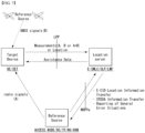
- FIG. 7 is a diagram illustrating an example of a positioning protocol configuration for measuring a location of a user equipment (UE).
- UE user equipment
- LPP may be used as a point-to-point between a location server (E-SMLC and/or SLP and/or LMF) and a target device to position the target device (UE and/or SET) based on position-related measurements obtained from one or more reference sources.
- the target device and the location server may exchange measurement and/or location information based on signal A and/or signal B through the LPP.
- NRPPa may be used to exchange information between the reference source (ACCESS NODE and/or BS and/or TP and/or NG-RAN nodes) and the location server.
- the reference source ACCESS NODE and/or BS and/or TP and/or NG-RAN nodes
- Functions provided by the NRPPa protocol may include the following.
- a positioning reference signal For positioning, a positioning reference signal (PRS) may be used.
- the PRS is a reference signal used for position estimation of the UE.
- PRS mapping in a wireless communication system to which embodiments are applicable in the present disclosure may be performed based on Table 6 below.
- Table 6 7.2 Physical resources The following antenna ports are defined for the downlink: - Antenna ports starting with 5000 for positioning reference signals The UE shall not assume that two antenna ports are quasi co-located with respect to any QCL type unless specified otherwise. 7.4.1.7 Positioning reference signals 7.4.1.7.1 General A positioning frequency layer consists of one or more downlink PRS resource sets, each of which consists of one or more downlink PRS resources as described in [6, TS 38.214].
- n s ,f ⁇ is the slot number
- the downlink PRS sequence ID n ID ,seq PRS ⁇ 0,1 , ... , 4095 is given by the higher-layer parameter DL-PRS-Sequenceld
- l is the OFDM symbol within the slot to which the sequence is mapped.
- - l start PRS is the first symbol of the downlink PRS within a slot and given by the higher-layer parameter DL-PRS-ResourceSymbolOffset
- - the size of the downlink PRS resource in the time domain L PRS ⁇ ⁇ 2,4,6,12 ⁇ is given by the higher-layer parameter DL-PRS-NumSymbols
- - the comb size K comb PRS ⁇ 2 4,6 12 is given by the higher-layer parameter transmissionComb
- - the resource-element offset k offset PRS ⁇ 0,1 , ... , K comb PRS ⁇ 1 is given by the higher-layer parameter
- the PRS reception procedure of the UE in a wireless communication system to which embodiments are applicable in the present disclosure may be performed based on Table 7 below.
- Table 7 5.1.6.5 PRS reception procedure
- the UE can be configured with one or more DL PRS resource set configuration(s) as indicated by the higher layer parameters DL-PRS-ResourceSet and DL-PRS-Resource.
- Each DL PRS resource set consists of K ⁇ 1 DL PRS resource(s) where each has an associated spatial transmission filter.
- the UE can be configured with one or more DL PRS Positioning Frequency Layer configuration(s) as indicated by the higher layer parameter DL-PRS-PositioningFrequencyLayer.
- a DL PRS Positioning Frequency Layer is defined as a collection of DL PRS Resource Sets which have common parameters configured by DL-PRS-PositioningFrequencyLayer. The UE assumes that the following parameters for each DL PRS resource(s) are configured via higher layer parameters DL-PRS-PositioningFrequencyLayer, DL-PRS-ResourceSet and DL-PRS-Resource.
- a positioning frequency layer consists of one or more PRS resource sets and it is defined by: - DL-PRS-SubcarrierSpacing defines the subcarrier spacing for the DL PRS resource.
- All DL PRS Resources and DL PRS Resource sets in the same DL-PRS-PositioningFrequencyLayer have the same value of DL-PRS-SubcarrierSpacing.
- the supported values of DL-PRS-SubcarrierSpacing are given in Table 4.2-1 of [4, TS38.211].
- - DL-PRS-CyclicPrefix defines the cyclic prefix for the DL PRS resource.
- All DL PRS Resources and DL PRS Resource sets in the same DL-PRS-PositioningFrequencyLayer have the same value of DL-PRS-CyclicPrefix.
- DL-PRS-CyclicPrefix The supported values of DL-PRS-CyclicPrefix are given in Table 4.2-1 of [4, TS38.211].
- - DL-PRS-PointA defines the absolute frequency of the reference resource block. Its lowest subcarrier is also known as Point A. All DL PRS resources belonging to the same DL PRS Resource Set have common Point A and all DL PRS Resources sets belonging to the same DL-PRS-PositioningFrequencyLayer have a common Point A.
- the UE expects that it will be configured with [IDs] each of which is defined such that it is associated with multiple DL PRS Resource Sets from the same cell.
- a PRS resource set consists of one or more PRS resources and it is defined by: - DL-PRS-ResourceSetId defines the identity of the DL PRS resource set configuration.
- - DL-PRS-ResourceRepetitionFactor defines how many times each DL-PRS resource is repeated for a single instance of the DL-PRS resource set and takes values T rep PRS ⁇ 1 2 4 6,8 16 32 ,. All the DL PRS resources within one resource set have the same ResourceRepetitionFactor - DL-PRS-ResourceTimeGap defines the offset in number of slots between two repeated instances of a DL PRS resource with the same DL-PRS-ResourceID within a single instance of the DL PRS resource set and takes values T gap PRS ⁇ 1 2 4,8 16 32 .
- the UE only expects to be configured with DL-PRS-ResourceTimeGap if DL-PRS-ResourceRepetitionFactor is configured with value greater than 1.
- the time duration spanned by one instance of a DL-PRS-ResourceSet is not expected to exceed the configured value of DL-PRS-Periodicity.
- All the DL PRS resources within one resource set have the same DL-PRS-ResourceTimeGap.
- - DL-PRS-MutingPattern defines a bitmap of the time locations where the DL PRS resource is expected to not be transmitted for a DL PRS resource set.
- the bitmap size can be ⁇ 2, 4, 8, 16, 32 ⁇ bits long.
- the bitmap has two options for applicability.
- each bit in the bitmap corresponds to a configurable number of consecutive instances of a DL-PRS-ResourceSet where all the DL-PRS-Resources within the set are muted for the instance that is indicated to be muted.
- each bit in the bitmap corresponds to a single repetition index for each of the DL-PRS-Resources within each instance of a DL-PRS-ResourceSet and the length of the bitmap is equal to DL-PRS-ResourceRepetitionFactor. Both options may be configured at the same time in which case the logical AND operation is applied to the bit maps as described in clause 7.4.1.7.4 of [4, TS 38.211].
- - DL-PRS-SFN0-Offset defines the time offset of the SFN0 slot 0 for the transmitting cell with respect to SFN0 slot 0 of [FFS in RAN2].
- - DL-PRS-ResourceSetSlotOffset defines the slot offset with respect to SFN0 slot 0 and takes values T offset PRS ⁇ 0,1 , ... , T per PRS ⁇ 1 .
- - DL-PRS-CombSizeN defines the comb size of a DL PRS resource where the allowable values are given in Clause 7.4.1 .7.1 of [TS38.211]. All DL PRS resource sets belonging to the same positioning frequency layer have the same value of DL-PRS-combSizeN.
- - DL-PRS-ResourceBandwidth defines the number of resource blocks configured for PRS transmission.
- the parameter has a granularity of 4 PRBs with a minimum of 24 PRBs and a maximum of 272 PRBs.
- All DL PRS resources sets within a positioning frequency layer have the same value of DL-PRS-ResourceBandwidth.
- a PRS resource is defined by: - DL-PRS-ResourceList determines the DL PRS resources that are contained within one DL PRS resource set.
- - DL-PRS-ResourceId determines the DL PRS resource configuration identity. All DL PRS resource IDs are locally defined within a DL PRS resource set.
- - DL-PRS-SequenceId is used to initialize cinit value used in pseudo random generator [4, TS38.211, 7.4.1.7.2] for generation of DL PRS sequence for a given DL PRS resource.
- - DL-PRS-ReOffset defines the starting RE offset of the first symbol within a DL PRS resource in frequency.
- the relative RE offsets of the remaining symbols within a DL PRS resource are defined based on the initial offset and the rule described in Clause 7.4.1.7.3 of [4, TS38.211].
- - DL-PRS-ResourceSlotOffset determines the starting slot of the DL PRS resource with respect to corresponding DL-PRS-ResourceSetSlotOffset
- - DL-PRS-ResourceSymbolOffset determines the starting symbol of the DL PRS resource within the starting slot.
- - DL-PRS-NumSymbols defines the number of symbols of the DL PRS resource within a slot where the allowable values are given in Clause 7.4.1.7.1 of [4, TS38.211].
- - DL-PRS-QCL-Info defines any quasi-colocation information of the DL PRS resource with other reference signals.
- the DL PRS may be configured to be 'QCL-Type-D' with a DL PRS or SS/PBCH Block from a serving cell or a non-serving cell.
- the DL PRS may be configured to be 'QCL-Type-C' with a SS/PBCH Block from a serving or non-serving cell. If the DL PRS is configured as both 'QCL-Type-C' and 'QCL-Type-D' with a SS/PBCH Block then the SSB index indicated should be the same.
- - DL-PRS-StartPRB defines the starting PRB index of the DL PRS resource with respect to reference Point A.
- the starting PRB index has a granularity of one PRB with a minimum value of 0 and a maximum value of 2176 PRBs. All DL PRS Resource Sets belonging to the same Positioning Frequency Layer have the same value of Start PRB.
- the UE assumes constant EPRE is used for all REs of a given DL PRS resource.
- the UE may be indicated by the network that a DL PRS resources can be used as the reference for the RSTD measurement in a higher layer parameter DL-PRS-RstdReferenceInfo.
- the reference time indicated by the network to the UE can also be used by the UE to determine how to apply higher layer parameters DL-PRS-expectedRSTD and DL-PRS-expectedRSTD-uncertainty.
- the UE expects the reference time to be indicated whenever it is expected to receive the DL PRS.
- This reference time provided by DL-PRS-RstdReferenceInfo may include an [ID], a PRS resource set ID, and optionally a single PRS resource ID or a list of PRS resource IDs.
- the UE may use different DL PRS resources or a different DL PRS resource set to determine the reference time for the RSTD measurement as long as the condition that the DL PRS resources used belong to a single DL PRS resource set is met. If the UE chooses to use a different reference time than indicated by the network, then it is expected to report the DL PRS resource ID(s) or the DL PRS resource set ID used to determine the reference.
- the UE may be configured to report quality metrics corresponding to the RSTD and UE Rx-Tx time difference measurements which include the following fields: - TimingMeasQuality-Value which provides the best estimate of the uncertainty of the measurement - TimingMeasQuality-Resolution which specifies the resolution levels used in the Value field
- the UE expects to be configured with higher layer parameter DL-PRS-expectedRSTD, which defines the time difference with respect to the received DL subframe timing the UE is expected to receive DL PRS, and DL-PRS-expectedRSTD-uncertainty, which defines a search window around the expectedRSTD.
- the UE can be configured to report the DL PRS resource ID(s) or the DL PRS resource set ID(s) associated with the DL PRS resource(s) or the DL PRS resource set(s) which are used in determining the UE measurements DL RSTD, UE Tx-Rx time difference or the DL PRS-RSRP.
- the UE can be configured in higher layer parameter UE Rx-Tx Time-MeasRequestInfo to report multiple UE Rx-Tx time difference measurements corresponding to a single configured SRS resource or resource set for positioning. Each measurement corresponds to a single received DL PRS resource or resource set which can be in difference positioning frequency layers.
- UE Rx-Tx Time-MeasRequestInfo For the DL RSTD, DL PRS-RSRP, and UE Rx-Tx time difference measurements the UE can report an associated higher layer parameter Timestamp.
- the Timestamp can include the SFN and the slot number for a subcarrier spacing. These values correspond to the reference which is provided by DL-PRS-RSTDReferenceInfo.
- the UE is expected to measure the DL PRS resource outside the active DL BWP or with a numerology different from the numerology of the active DL BWP if the measurement is made during a configured measurement gap.
- the UE is only required to measure DL PRS within the active DL BWP and with the same numerology as the active DL BWP.
- the UE is not provided with a measurement gap, the UE is not expected to process DL PRS resources on serving or non-serving cells on any symbols indicated as UL by the serving cell.
- the UE is expected to measure the DL PRS resource outside the active DL BWP it may request a measurement gap in higher layer parameter [XYZ].
- the UE assumes that for the serving cell the DL PRS is not mapped to any symbol that contains SS/PBCH. If the time frequency location of the SS/PBCH block transmissions from non-serving cells are provided to the UE then the UE also assumes that the DL PRS is not mapped to any symbol that contains the SS/PBCH block of the non-serving cell.
- the UE may be configured to report, subject to UE capability, up to 4 DL RSTD measurements per pair of cells with each measurement between a different pair of DL PRS resources or DL PRS resource sets within the DL PRS configured for those cells. The up to 4 measurements being performed on the same pair of cells and all DL RSTD measurements in the same report use a single reference timing.
- the UE may be configured to measure and report up to 8 DL PRS RSRP measurements on different DL PRS resources from the same cell.
- the UE may indicate which DL PRS RSRP measurements have been performed using the same spatial domain filter for reception. If the UE is configured with DL-PRS-QCL-Info and the QCL relation is between two DL PRS resources, then the UE assumes those DL PRS resources are from the same cell.
- DL-PRS-QCL-Info is configured to the UE with 'QCL-Type-D' with a source DL-PRS-Resource then the DL-PRS-ResourceSetId and the DL-PRS-Resourceld of the source DL-PRS-Resource are expected to be indicated to the UE.
- the UE does not expect to process the DL PRS in the same symbol where other DL signals and channels are transmitted to the UE when there is no measurement gap configured to the UE.
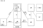
- FIG. 8 is a diagram illustrating an example of architecture of a system for measuring a location of an UE.
- the AMF may receive a request for location service related to a specific target UE from another entity such as the GMLC (Gateway Mobile Location Center), or may decide to start the location service on behalf of the specific target UE in the AMF itself. Then, the AMF transmits a location service request to the LMF (Location Management Function).
- the LMF receiving the location service request may process the location service request and return a processing result including the estimated location of the UE to the AMF.
- the AMF may transmit the processing result received from the LMF to another entity.
- New generation evolved-NB (ng-eNB) and gNB may be network elements of NG-RAN that can provide measurement results for location tracking, and measure a radio signal for the target UE and transmit the result to the LMF.
- the ng-eNB may control some TPs (Transmission Points), such as remote radio heads, or PRS-only TPs supporting a PRS-based beacon system for E-UTRA.
- TPs Transmission Points
- the LMF may be connected to an Enhanced Serving Mobile Location Center (E-SMLC), and the E-SMLC may enable the LMF to access the E-UTRAN.
- E-SMLC may enable the LMF to support Observed Time Difference Of Arrival (OTDOA) which is one of the E-UTRAN positioning measurement methods, based on the downlink measurement which is obtained by the target UE through a signal transmitted from TPs dedicated for PRS in the eNB and/or E-UTRAN.
- OTDOA Observed Time Difference Of Arrival
- the LMF may be connected to a SUPL Location Platform (SLP).
- the LMF may support and manage different location services for target UEs.
- the LMF may interact with the serving ng-eNB or serving gNB for the target UE to obtain the location measurement of the UE.
- the LMF may determine a positioning measurement method based on Location Service (LCS) client type, required QoS (Quality of Service), UE positioning capabilities, and gNB positioning capabilities and ng-eNB positioning capabilities, and apply this positioning measurement method to the serving gNB and/or the serving ng-eNB.
- the LMF may determine a position estimate for the target UE and additional information such as accuracy of the position estimate and velocity.
- the SLP is a SUPL (Secure User Plane Location) entity responsible for positioning through a user plane.
- the UE may measure the location of the UE by utilizing a downlink reference signal transmitted from the NG-RAN and the E-UTRAN.
- the downlink reference signal transmitted from the NG-RAN and the E-UTRAN to the UE may include an SS/PBCH block, CSI-RS and/or PRS, etc., and whether to measure the location of the UE using any downlink reference signal may depend on a configuration such as LMF/E-SMI,C/ng-eNB/E-UTRAN, etc.
- the location of the UE may be measured in a RAT-independent method using different GNSS (Global Navigation Satellite System), TBS (Terrestrial Beacon System), WLAN access points, Bluetooth beacon and a sensor (e.g.
- the UE may include an LCS application, and access the LCS application through communication with a network to which the UE is connected or other applications included in the UE.
- the LCS application may include measurement and calculation functions necessary to determine the location of the UE.
- the UE may include an independent positioning function such as Global Positioning System (GPS), and may report the location of the UE independently of NG-RAN transmission.
- GPS Global Positioning System
- the independently acquired positioning information may be utilized as auxiliary information of positioning information acquired from the network.
- FIG. 9 is a diagram illustrating an example of a procedure for measuring a location of a UE.
- CM-IDLE Connection Management - IDLE
- the AMF may establish a signaling connection with the UE, and request a network trigger service to allocate a specific serving gNB or ng-eNB.
- This operation process is omitted in FIG. 9 . That is, in FIG. 8 , it may be assumed that the UE is in a connected mode. However, the signaling connection may be released during the positioning process by the NG-RAN for reasons such as signaling and data inactivity.
- a 5GC entity such as GMLC may request a location service for measuring the location of a target UE with a serving AMF.
- the serving AMF may determine that the location service is necessary for measuring the location of the target UE. For example, in order to measure the location of the UE for an emergency call, the serving AMF may decide to directly perform the location service.
- the AMF may send a location service request to the LMF, and based on step 3a, the LMF may initiate location procedures for obtaining location measurement data or location measurement assistance data together with the serving ng-eNB and the serving gNB.
- the LMF may request location-related information related to one or more UEs to the NG-RAN, and instruct the type of location information required and the associated QoS.
- the NG-RAN may transmit the location-related information to the LMF.
- the NG-RAN may transmit additional location-related information to the LMF through one or more NRPPa messages.
- 'location-related information' may mean all values used for location calculation, such as actual location estimation information and wireless measurement or location measurement, etc.
- the protocol used in step 3a may be an NRPPa protocol, which will be described later.
- the LMF may initiate location procedures for downlink positioning with the UE.
- the LMF may send location assistance data to the UE, or obtain a location estimate or location measurement.
- a capability transfer process may be performed.
- the LMF may request capability information from the UE, and the UE may transmit capability information to the LMF.
- the capability information may include information on a location measurement method that the LFM or UE can support, information on various aspects of a specific location measurement method, such as various types of assistance data for A-GNSS, and information on common characteristics that are not limited to any one location measurement method, such as the ability to handle multiple LPP transactions, etc.
- the UE may provide capability information to the LMF.
- a location assistance data transfer process may be performed in step 3b.
- the UE may request location assistance data from the LMF, and may indicate required specific location assistance data to the LMF.
- the LMF may deliver location assistance data corresponding thereto to the UE, and additionally, may transmit additional assistance data to the UE through one or more additional LPP messages.
- location assistance data transmitted from the LMF to the UE may be transmitted through a unicast method, and in some cases, the LMF may transmit location assistance data and/or additional assistance data to the UE without the UE requesting assistance data from the LMF.
- a location information transfer process may be performed in step 3b.
- the LMF may request the UE for location-related information related to the UE, and may indicate the type of location information required and the associated QoS. Then, in response to the request, the UE may transmit the location related information to the LMF. In this case, the UE may additionally transmit additional location-related information to the LMF through one or more LPP messages.
- 'location-related information' may mean all values used for location calculation, such as actual location estimation information and wireless measurement or location measurement, etc, and representatively, there may be a Reference Signal Time Difference (RSTD) value measured by the UE based on downlink reference signals transmitted from a plurality of NG-RAN and/or E-UTRAN to the UE. Similar to the above, the UE may transmit the location-related information to the LMF even if there is no request from the LMF.
- RSTD Reference Signal Time Difference
- step 3b is performed in the order of a capability transfer process, an assistance data transfer process, and a location information transfer process, but is not limited to this order.
- step 3b is not limited to a specific order in order to improve the flexibility of location measurement.
- the UE may request location assistance data at any time to perform the location measurement request already requested by the LMF.
- the LMF may also request location information, such as location measurements or location estimates, at any time.
- the UE may transmit capability information to the LMF at any time.
- an Error message may be transmitted/received, and an Abort message may be transmitted/received for stopping position measurement.
- the protocol used in step 3b may be an LPP protocol, which will be described later.
- step 3b may be additionally performed after step 3a is performed, or may be performed instead of step 3a.
- the LMF may provide a location service response to the AMF.
- the location service response may include information on whether the location estimation of the UE was successful and the location estimate of the UE.
- the AMF may deliver a location service response to a 5GC entity such as GMLC, and if the procedure of FIG. 9 is initiated by step 1b, the AMF may use a location service response to provide a location service related to an emergency call or the like.
- -NR-Uu interface The NR-Uu interface, connecting the UE to the gNB over the air, is used as one of several transport links for the LTE Positioning Protocol for a target UE with NR access to NG-RAN.
- - LTE-Uu interface The LTE-Uu interface, connecting the UE to the ng-eNB over the air, is used as one of several transport links for the LTE Positioning Protocol for a target UE with LTE access to NG-RAN.
- the NG-C interface between the gNB and the AMF and between the ng-eNB and the AMF is transparent to all UE-positioning-related procedures. It is involved in these procedures only as a transport link for the LTE Positioning Protocol.
- the NG-C interface transparently transports both positioning requests from the LMF to the gNB and positioning results from the gNB to the LMF.
- the NG-C interface transparently transports both positioning requests from the LMF to the ng-eNB and positioning results from the ng-eNB to the LMF.
- the NLs interface between the LMF and the AMF, is transparent to all UE related, gNB related and ng-eNB related positioning procedures. It is used only as a transport link for the LTE Positioning Protocols LPP and NRPPa.
- LTP LTE Positioning Protocol
- FIG. 10 is a diagram illustrating an example of a protocol layer for supporting LPP message transmission.
- an LPP PDU may be transmitted through a NAS PDU between the MAF and the UE.
- the LPP may terminate a connection between a target device (e.g. UE in the control plane or SUPL Enabled Terminal (SET) in the user plane) and a location server (e.g. LMF in the control plane or SLP in the user plane).
- the LPP message may be delivered in the form of a transparent PDU through an intermediate network interface using an appropriate protocol such as NGAP through the NG-C interface, NAS/RRC through the LTE-Uu and NR-Uu interfaces.
- the LPP protocol enables positioning for NR and LTE based on various positioning methods.
- the target device and the location server may exchange capability information, assistance data for positioning, and/or location information with each other through the LPP protocol.
- error information exchange and/or an instruction to stop the LPP procedure may be performed through the LPP message.
- a signal transmission/reception operation based on the LPP protocol to which the method proposed in the present disclosure can be applied may be performed based on Table 9 below.
- Table 9 As described above, the protocol operates between a "target" and a "server". In the control-plane context, these entities are the UE and LMF respectively; in the SUPL context they are the SET and the SLP. A procedure may be initiated by either the target or the server.
- Capability Transfer Capabilities in an LPP context refer to the ability of a target or server to support different position methods defined for LPP, different aspects of a particular position method (e.g. different types of assistance data for A-GNSS) and common features not specific to only one position method (e.g. ability to handle multiple LPP transactions).
- LPP Capability Transfer procedure 1 The server may send a request for the LPP related capabilities of the target. 2. The target transfers its LPP-related capabilities to the server. The capabilities may refer to particular position methods or may be common to multiple position methods. LPP Capability Indication procedure is used for unsolicited capability transfer. 2) Assistance data Transfer Assistance data may be transferred either by request or unsolicited.
- assistance data delivery is supported only via unicast transport from server to target.
- Example of LPP Assistance Data Transfer procedure 1.
- the target may send a request to the server for assistance data and may indicate the particular assistance data needed.
- the server transfers assistance data to the target.
- the transferred assistance data should match any assistance data requested in step 1.
- the server may transfer additional assistance data to the target in one or more additional LPP messages.
- LPP Assistance Data Delivery procedure is used for unilateral assistance data transfer. This procedure is unidirectional; assistance data are always delivered from the server to the target.
- Location Information Transfer The term "location information" applies both to an actual position estimate and to values used in computing position (e.g., radio measurements or positioning measurements). It is delivered either in response to a request or unsolicited.
- Example of LPP Location Information Transfer procedure 1 The server may send a request for location information to the target, and may indicate the type of location information needed and associated QoS. 2. In response to step 1, the target transfers location information to the server. The location information transferred should match the location information requested in step 1. 3. Optionally (e.g., if requested in step 1), the target in step 2 may transfer additional location information to the server in one or more additional LPP messages.
- LPP Location Information Delivery procedure is used for unilateral location information transfer. Furthermore, the LPP Location Information Delivery procedure can only be piggybacked in the MO-LR request. 4) Multiple Transactions Multiple LPP transactions may be in progress simultaneously between the same target and server nodes, to improve flexibility and efficiency.
- no more than one LPP procedure between a particular pair of target and server nodes to obtain location information shall be in progress at any time for the same position method.
- the objective is to request location measurements from the target, and the server does not provide assistance data in advance, leaving the target to request any needed assistance data.
- Example of multiple LPP procedures 1.
- the server sends a request to the target for positioning measurements. 2.
- the target sends a request for particular assistance data. 3.
- the server returns the assistance data requested in step 2.
- the target obtains and returns the location information (e.g., positioning method measurements) requested in step 1. 5) Error handling
- the procedure is used to notify the sending endpoint by the receiving endpoint that the receiving LPP message is erroneous or unexpected.
- This procedure is bidirectional at the LPP level; either the target or the server may take the role of either endpoint in the corresponding procedure.
- Example of Error handling procedure 1. The target or server sends a LPP message to the other endpoint (i.e, "Server/Target"). 2. If the server or target ("Server/Target") detects that the receiving LPP message is erroneous or unexpected, the server or target transfers error indication information to the other endpoint ("Target/Server"). 6) Abort The procedure is used to notify the other endpoint by one endpoint to abort an ongoing procedure between the two endpoints. This procedure is bidirectional at the LPP level; either the target or the server may take the role of either endpoint in the corresponding procedure.
- Example of Abort procedure A LPP procedure is ongoing between target and server. 2. If the server or target (“Server/Target”) determines that the procedure must be aborted, and then the server or target sends an LPP Abort message to the other endpoint ("Target/Server”) carrying the transaction ID for the procedure.
- server/Target the server or target
- NRPPa NR Positioning Protocol A
- FIG. 11 is a diagram illustrating an example of a protocol layer for supporting NRPPa transmission. Specifically, FIG. 11 illustrates a protocol layer for supporting transmission of an NRPPa PDU (NR Positioning Protocol a Protocol Data Unit).
- NRPPa PDU NR Positioning Protocol a Protocol Data Unit
- the NRPPa may be used for information exchange between the NG-RAN node and the LMF. Specifically, the NRPPa may used to exchange E-CID for measurement transmitted from ng-eNB to LMF, data for supporting the OTDOA positioning method, Cell-ID and Cell location ID for the NR Cell ID positioning method, and the like.
- the AMF may route NRPPa PDUs based on the routing ID of the associated LMF through the NG-C interface even if there is no information on the associated NRPPa transaction.
- the procedure of the NRPPa protocol for location and data collection can be divided into two types.
- the first type is a UE associated procedure for delivering information on a specific UE (e.g. location measurement information, etc.)
- the second type is a non-UE associated procedure for delivering information applicable to an NG-RAN node and related TPs (e.g. gNB/ng-eNG/TP timing information, etc.).
- the two types of procedures may be supported independently or at the same time.
- a signal transmission/reception operation based on the NRPPa protocol to which the embodiments proposed in the present disclosure can be applied may be performed based on Table 10 below.
- Table 10 Positioning and data acquisition transactions between a LMF and NG-RAN node are modelled by using procedures of the NRPPa protocol.
- NRPPa procedures There are two types of NRPPa procedures: - UE associated procedure, i.e. transfer of information for a particular UE (e.g. positioning measurements); - Non UE associated procedure, i.e. transfer of information applicable to the NG-RAN node and associated TPs (e.g. gNB/ng-eNBfTP timing information).
- Parallel transactions between the same LMF and NG-RAN node are supported; i.e.
- a pair of LMF and NG-RAN node may have more than one instance of an NRPPa procedure in execution at the same time.
- the protocol is considered to operate between a generic "access node” (e.g. ng-eNB) and a “server” (e.g. LMF).
- a procedure is only initiated by the server.
- Example of a single NRPPa transaction 1. Access Node sends NRPPa Procedure Request to Server. 2. Server sends NRPPa Procedure Response to Acces Node. N. Access Node sends NRPPa Procedure Response (end transaction) to Server. (this step may be omitted).
- the exmaple shows a single NRPPa transaction. The transaction is terminated in step 2 in the case of a non UE associated procedure.
- LPPa transaction type may be "Location Information Transfer".
- location information applies both to an actual position estimate and to values used in computing position (e.g., radio measurements or positioning measurements). It is delivered in response to a request.
- the server sends a request for location related information to the NG-RAN node, and indicates the type of location information needed and associated QoS.
- the request may refer to a particular UE.
- the NG-RAN Node transfers location related information to the server.
- the location related information transferred should match the location related information requested in step 1.
- the NG-RAN node may transfer additional location related information to the server in one or more additional NRPPa messages when the positioning method is E-CID for E-UTRA.
- a message exchanged (transmitted and received) between a UE (a target device)/location server for positioning and a configuration related to the message may be based on Table 11 below.
- the positioning measurement methods supported by NG-RAN may include GNSS, OTDOA, E-CID (enhanced cell ID), Multi RTT (round trip time)/Multi-cell RTT, barometric pressure sensor positioning, WLAN positioning, Bluetooth positioning, and TBS (terrestrial beacon system), UTDOA (Uplink Time Difference of Arrival), etc.
- GNSS Global System for Mobile Communications
- OTDOA enhanced cell ID
- E-CID enhanced cell ID
- Multi RTT round trip time
- Multi-cell RTT barometric pressure sensor positioning
- WLAN positioning Bluetooth positioning
- TBS terrestrial beacon system
- UTDOA Uplink Time Difference of Arrival
- OTDOA Observed Time Difference Of Arrival
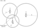
- FIG. 12 is a diagram illustrating an example of an OTDOA positioning measurement method.
- the OTDOA positioning measurement method uses the measurement timing of downlink signals received by the UE from multiple TPs including an eNB, an ng-eNB, and a PRS-only TP.
- the UE measures the timing of the received downlink signals by using the location assistance data received from the location server.
- the location of the UE may be determined based on these measurement results and the geographic coordinates of the contiguous TPs.
- a UE connected to the gNB may request a measurement gap for OTDOA measurement from the TP. If the UE does not recognize the SFN for at least one TP in the OTDOA assistance data, the UE may use the autonomous gap to obtain the SFN of the OTDOA reference cell before requesting the measurement gap for performing Reference Signal Time Difference (RSTD) measurement.
- RSTD Reference Signal Time Difference
- the RSTD may be defined based on the smallest relative time difference between the boundaries of two subframes respectively received from the reference cell and the measurement cell. That is, it may be calculated based on the relative time difference between the start times of the subframes of the reference cell closest to the start time of the subframe received from the measurement cell. Meanwhile, the reference cell may be selected by the UE.
- the TOA for each of TP 1 , TP 2 and TP 3 may be measured, the RSTD for TP 1-TP 2, the RSTD for TP 2-TP 3, and the RSTD for TP 3-TP 1 may be calculated based on the three TOAs, a geometric hyperbola may be determined based on this, and a point where these hyperbola intersects may be estimated as the location of the UE.
- the estimated location of the UE may be known as a specific range depending on the measurement uncertainty.
- RSTDs for two TPs may be calculated based on Equation 3 below.
- RSTD i , 1 x t ⁇ x i 2 + y t ⁇ y i 2 c ⁇ x t ⁇ x 1 2 + y t ⁇ y 1 2 c + T i ⁇ T 1 + n i ⁇ n 1
- c may be the speed of light
- ⁇ xt, yt ⁇ may be the (unknown) coordinates of the target UE
- ⁇ xi, yi ⁇ may be the coordinates of the (known) TP
- ⁇ 25, y1 ⁇ may be the coordinates of the reference TP (or other TP).
- (Ti-T1) is a transmission time offset between two TPs, which may be referred to as "Real Time Differences" (RTDs)
- ni and n1 may represent values related to UE TOA measurement errors.
- E-CID Enhanced Cell ID
- the location of the UE may be measured through geographic information of the serving ng-eNB, the serving gNB and/or the serving cell of the UE.
- geographic information of the serving ng-eNB, the serving gNB, and/or the serving cell may be obtained through paging, registration, or the like.
- the E-CID positioning measurement method may use additional UE measurement and/or NG-RAN radio resources and the like for improving the UE location estimate in addition to the CID positioning measurement method.
- some of the same measurement methods as those of the measurement control system of the RRC protocol may be used, but in general, additional measurement is not performed only for the location measurement of the UE.
- a separate measurement configuration or measurement control message may not be provided to measure the location of the UE, and the UE also does not expect that an additional measurement operation only for location measurement will be requested, and the UE may report a measurement value obtained through generally measurable measurement methods.
- the serving gNB may implement the E-CID positioning measurement method using the E-UTRA measurement provided from the UE.
- An example of a measurement element that can be used for E-CID positioning may be as follows.
- TADV may be divided into Type 1 and Type 2 as follows.
- TADV Type 1 (ng-eNB reception-transmission time difference) + (UE E-UTRA reception-transmission time difference)
- TADV Type 2 ng ⁇ eNB reception ⁇ transmission time difference
- AoA may be used to measure the direction of the UE.
- AoA may be defined as an estimated angle for the location of the UE in a counterclockwise direction from the base station/TP. In this case, the geographic reference direction may be north.
- the base station/TP may use an uplink signal such as a sounding reference signal (SRS) and/or a demodulation reference signal (DMRS) for AoA measurement.
- SRS sounding reference signal
- DMRS demodulation reference signal
- the larger the antenna array arrangement the higher the AoA measurement accuracy, when the antenna arrays are arranged at the same interval, signals received from contiguous antenna elements may have a constant phase-rotate.
- UTDOA is a method of determining the location of the UE by estimating the arrival time of the SRS.
- the location of the UE may be estimated through the difference in arrival time with another cell (or base station/TP) by using the serving cell as a reference cell.
- the E-SMLC may instruct the serving cell of the target UE to instruct the target UE to transmit SRS.
- the E-SMLC may provide configuration such as whether the SRS is periodic/aperiodic, bandwidth, and frequency/group/sequence hopping, etc.
- Multi-cell RTT Multi-cell RTT
- RTT is based on TOA measurement like the OTDOA, but requires only coarse TRP (e.g. base station) timing synchronization.
- TRP e.g. base station
- FIGS. 13A and 13B are diagrams illustrating an example of a Multi RTT positioning measurement method.
- an RTT process in which TOA measurement is performed in an initiating device and a responding device, and the responding device provides the TOA measurement to the initiating device for RTT measurement (calculation), is exemplified.
- the initiating device may be a TRP and/or a UE
- the responding device may be the UE and/or the TRP.
- the initiating device may transmit an RTT measurement request, and the responding device may receive it.
- the initiating device may transmit an RTT measurement signal at t0, and the responding device may acquire a TOA measurement t1.
- the responding device may transmit the RTT measurement signal at t2, and the initiating device may acquire a TOA measurement t3.
- the responding device may transmit information on [t2-t1], and the initiating device may receive the corresponding information and calculate the RTT based on Equation 4 below.
- the corresponding information may be transmitted/received based on a separate signal, or may be transmitted/received by being included in the RTT measurement signal of B805.
- RTT t 3 ⁇ t 0 ⁇ t 2 ⁇ t 1
- the corresponding RTT may correspond to double-range measurement between two devices. Positioning estimation may be performed from the corresponding information, and a multilateration technique may be used. Based on the measured RTT, d1, d2, and d3 may be determined, and the target device location may be determined by the intersection of the circumference with each BS1, BS2, BS3 (or TRP) as a center and each d1, d2, and d3 as a radius.
- a UE reports a result of location measurement to a location server (e.g., LMF)
- the UE reports a reference signal received power (RSRP) which is a linear average of received strengths for resource elements (REs) in which a PRS within an indicated frequency band is transmitted.
- RSRP reference signal received power
- LoS/NLoS in a signal path between a base station (BS) and a UE is more important than a channel environment, but it is not guaranteed that a path of the corresponding signal is line of sight (LoS) even if the reported RSRP is high. This is because a signal sent by transmitting a specific material may have a weak received strength even if the signal path is the LoS.
- a report per path e.g., a report for DL PRS RSRPP
- a report of a received signal strength on a per RE basis e.g., a report for DL PRS RSRP
- the UE may measure and report the power of a linear average of channel responses at an i-th path (e.g., i-th path delay) of REs carrying PRS.
- the measurement value may be referred to as DL PRS reference signal received path power (RSRPP).
- the DL PRS RSRP may follow the definition described in Table 12.
- the DL PRS RSRPP may follow the definition described in Table 13.
- DL PRS-RSRPP DL PRS reference signal received path power
- the reference point for the DL PRS-RSRPP shall be the antenna connector of the UE.
- DL PRS-RSRPP shall be measured based on the combined signal from antenna elements corresponding to a given receiver branch.
- the reported DL PRS-RSRPP value included in the higher layer parameter NR- DL-AoD-MeasElement for the first and additional measurements shall be provided for the same receiver branch(es) as applied for DL PRS-RSRP measurements. Applicable for RRC_CONNECTED, RRC_INACTIVE
- DL PRS-RSRPP for a first path may be power contribution corresponding to a first detected path in time.
- the maximum number of paths that the UE can report based on UE's capability related to the report per path may be defined/configured.
- the UE may not support a path specific measurement.
- the UE may support measurement for one path (first path) (e.g., DL PRS RSRPP measurement for the first path).
- the UE may support measurement for two or more paths (e.g., DL PRS RSRPP measurement for the first path + DL PRS RSRPP measurement for one or more additional paths).
- a path specific reporting system of the UE When the UE reports a result of location measurement, a path specific reporting system of the UE is described in detail below.
- a first path among paths related to path specific measurement of the UE may be referred to as a first arrival path (or first path), and additional paths other than the first path may be referred to as additional 'N' paths (or additional paths), where 'N' is the maximum number of additional paths supported by the UE and may be an integer greater than or equal to 1.
- 'N' may be set to 4, 6 or 8.
- the UE/BS may report a result of path specific measurement to a location server.
- the path specific measurement may be based on a timing based positioning measurement (e.g., DL-TDOA, UL-TDOA, multi-RTT) or an angle based positioning measurement (e.g., DL-AoD, LTL-AoA).
- a timing based positioning measurement e.g., DL-TDOA, UL-TDOA, multi-RTT
- an angle based positioning measurement e.g., DL-AoD, LTL-AoA
- the UE may report a measurement result for the first path and one or more additional paths.
- the report per path may include at least one of RSRP (e.g., DL PRS-RSRPP), timing related measurement, and/or angle related measurement.
- the UE may transmit, to the location server, an LPP message (e.g., ProvideLocationInformation message) including DL PRS-RSRPP for the first path.
- the UE may transmit, to the location server, an LPP message (e.g., ProvideLocationInformation message) including DL PRS-RSRPP for the first path and DL PRS-RSRPP for one or more additional paths.
- information on the DL PRS-RSRPP may be included in NR-DL-TDOA-ProvideLocationInformation or NR-Multi-RTT-ProvideLocationInformation in the LPP message based on a positioning method (e.g., DL-TDOA or Multi-RTT).
- a positioning method e.g., DL-TDOA or Multi-RTT.
- the UE may transmit information on the maximum number of measurement reports related to multiple paths when reporting capability for a measurement report to the base station or the location server (e.g., LMF).
- the path specific report described in the present disclosure may refer to a report including all the first arrival path (FAP) and the additional paths.
- FAP first arrival path
- the order of first, second, third, ..., n-th arrival paths is defined in time. That is, DL PRS-RSRPP related to the first path may be related to the first detected signal in time, and the third path may be related to the third detected signal in time.
- the UE reports up to the n-th path it may mean that the UE reports the first, second, third, ..., n-th arrival paths.
- a UE may receive a capability request from a location server (e.g., LMF) or the UE itself may report a capability for a path specific report to the location server (e.g., LMF).
- a location server e.g., LMF
- LMF location server
- the UE may receive, from the location server, an LPP message (e.g., RequestCapabilities message) related to the capability request.
- the UE may transmit, to the location server, an LPP message (e.g., ProvideCapabilities message) including capability information requested by the location server.
- an LPP message e.g., ProvideCapabilities message
- the UE may report the capability even if there is no request from the location server.
- the UE may transmit, to the location server, an LPP message (e.g., ProvideCapabilities message) including capability information that is not requested by the location server.
- LPP message e.g., ProvideCapabilities message
- the LPP message related to each of the request/provision of the capability may include information (request informatopn/provision infomation) on a capability related to a positioning method.
- the RequestCapabilities message may include nr-DL-TDOA-RequestCapabilities and/or nr-Multi-RTT-RequestCapabilities.
- the ProvideCapabilities message may include nr-DL-TDOA-ProvideCapabilities and/or nr-Multi-RTT-ProvideCapabilities.
- the RequestCapabilities message/ProvideCapabilities message may include information as defined in Table 11.
- the UE may report a measurement capability for multiple paths separately for each positioning method.
- the UE may transmit, to the location server, capability information including i) information (e.g., supportOfDL-PRS-FirstPathRSRP) indicating whether measurement for a first path is supported and/or ii) information (e.g., additionalPathsExtSupport) indicating whether measurement for additional paths is supported, for each positioning method (e.g., Multi-RTT, DL-TDOA).
- the additionalPathsExtSupport may indicate the number of additional paths supported by the UE (e.g., 4, 6 or 8 paths).
- the capability information for each positioning method may mean NR-Multi-RTT-ProvideCapabilities and/or NR-DL-TDOA-ProvideCapabilities in the ProvideCapabilities message.
- the UE may report a measurement capability for multiple paths common to the positioning method.
- the capability information reported by the UE may include information related to at least one of i) whether a first arrival path can be reported, ii) whether additional paths can be reported, and/or iii) the maximum number of reports that can be reported for each path. The maximum number may be commonly applied to all reported elements, or may be indicated and configured for each element.
- the UE can report up to four additional paths upon the capability report for DL-AoD.
- the RSRP e.g., DL PRS-RSRPP
- timing information such as additionally reported RSTD or TOA or RX-Tx timing difference, may also be reported for each of the four additional paths.
- the UE may separately report the RSRP reported for each additional path or the maximum number for each measurement result element of timing.
- the UE may report that i) a path specific RSRP (DL PRS-RSRPP) can be reported up to an m-th path and ii) timing measurement information as well as the path specific RSRP can be reported together up to a k-th path.
- DL PRS-RSRPP path specific RSRP
- timing measurement information as well as the path specific RSRP can be reported together up to a k-th path.
- the location server may request only specific information with respect to the information described above from the UE upon the capability request.
- the UE may deliver a report on the capability to a base station, and the base station may also request information on the capability of the UE from the UE.
- the capability may be related to up to n path specific reports (or 1 (first path) + N (additional paths) path specific reports) supported from a UE perspective.
- the UE may dividedly report TRP or resource(s) or set upon the measurement report within the reported n (or 1+N) reports.
- the UE may perform the up to n path specific reports individually supported per band or per band combination.
- the measurement report may be performed per feature set of the UEs supporting the path specific reports.
- the UE sends the capability to the location server (e.g., LMF) or the base station as described above, a problem arises as to whether the UE shall always follow the reported capability.
- the measurement report of the UE is described below.
- a UE may perform measurement reporting as many as the number of reports reported to a location server based on capability information.
- the UE may report the measurement results.
- a base station or the location server e.g., LMF
- LMF location server
- different path specific reports may be derived by mapping the measurement results of each positioning measurement and tabulating each result value. That is, taking legacy RSRP as an example, it may be pre-configured so that only (up to) m paths are reported for -130 ⁇ RSRP ⁇ -120 dBm and only (up to) n paths are reported for -120 ⁇ RSRP ⁇ -110 dBm. If paths less than 'm' or 'n' within the above range are detected, m-x or n-y reports may be reported as 0 or processed as a reserved value (e.g., x ⁇ m and y ⁇ n). This has advantages of preventing reporting of unnecessary information and in terms of efficient use of resources, and the UE always performs reports as much as its capabilities.
- a report on the maximum number of additional paths based on the RSRP i.e., RSRPP
- angle and/or timing for the first arrival path may be pre-configured as above.
- the location server (e.g., LMF) may differently pre-configure measurement results of additional paths per TRP. This is to request TRPs, which are judged to be meaningful, to report a larger number of paths and to request TRPs, which are judged to be meaningless, to report FAP or a small number of additional paths for PRS measurement, considering a distance between the UE and the TRP.
- the location server (e.g., LMF) may know location information of the TRP, and the location information may be obtained from 2D or 3D distance considering an approximate location of the UE ( ⁇ a-priori estimation of the target device location').
- the location server e.g., LMF
- the base station may transmit, to the UE, expected RSRP (including uncertainty) information or expected path RSRP (including uncertainty) information based on the above-described embodiment. That is, the UE may perform a report on a path RSRP satisfying a power range according to an expected RSRP or an expected path RSRP.
- the expected RSRP or the expected path RSRP may be n dBm, and the uncertainty may limit the reporting of the report TRP or path by +- offset regarding the preceding n dBm in the range.
- the above-described expected RSRP/expected path RSRP related information may be transmitted regarding the number of paths required per TRP based on system information or assistance data.
- the above-described expected RSRP/expected path RSRP related information may be configured so that the same number of additional paths can be reported by grouping TRPs into groups or sets.
- bundle information of TRPs that refers to a bundle of contiguous TRPs and enables the same number of paths to be measured and reported for the TRPs belonging to the bundle, may be configured.
- a location server may transmit information related to a path specific report through a measurement result request message, and a UE may perform measurement/reporting on the indicated/set number of paths.
- the location server may transmit, to the UE, information indicating a request for measurement and reporting for a first path.
- the UE may report only a measurement result for the first path to the location server.
- the location server may transmit, to the UE, information indicating a request for measurement and reporting for the first path and information indicating a request for measurement and reporting for additional path(s).
- the UE may report measurement results for the first path and the additional path(s) to the location server.
- the number (e.g., 4, 6 or 8) of the additional path(s) may be based on capability information of the UE transmitted to the location server as described above.
- the location server (e.g., LMF) may indicate/configure to the UE based on a reported capability so that the number of paths based on the capability or a smaller number of path(s) are measured/reported.
- the UE may perform measurement and reporting based on the indicated/configured number and contents.
- path specific related information same as the maximum number of paths to be reported may be included in a request message for location information transmitted from the location server (e.g., LMF) to the UE, and the UE may always perform the reporting as many as the indicated/configured number.
- the location server may indicate whether measurement information for the first path is required based on information (e.g., nr-RequestedMeasurements) in an LPP message (e.g., RequestLocationInformation message).
- the location server may indicate to provide measurement information related to additional paths based on information (e.g., additionalPaths) in the LPP message (e.g., RequestLocationInformation message).
- the measurement information related to the additional paths may be defined in nr-AdditionalPathList.
- the nr-AdditionalPathList may include measurement information (e.g., DL PRS RSRPP) for each path of paths based on the number supported by the UE.
- the UE may include measurement information (e.g., DL PRS-RSRPP) for paths of the number (e.g., 4, 6 or 8) based on the capability in the nr-AdditionalPathList and report it.
- the maximum number of paths to be reported may be indicated/configured per positioning method (e.g., indicated/configured for each of DL-TDOA and multi-RTT), or commonly indicated/configured regardless of the positioning method. For example, 1) for the DL-TDOA method, only the measurement for the first path may be indicated and the measurement for the additional paths may not be indicated, and 2) for the multi-RTT method, the measurement for the first path and the additional paths may be indicated.
- the location server may differently configure and request a measurement result element to be reported for each path.
- a request (LPP message) of the location server may indicate the UE to report measurement results as in the following 1) and 2).
- M is the maximum number of reportable additional paths (e.g., the number N of additional paths supported by the UE other than the first path) transmitted through a capability report from the UE.
- the above-described operation i.e., the reporting operation of the UE according to the 1) and 2)
- the present embodiment can be applied to the operation for measurement result requests for all the positioning methods.
- the present embodiment can be applied to an operation (operation of the location server) for a measurement result request for the DL-AoD method and a UE operation based on the request.
- the location server may indicate/set the number of paths for which a measurement result is requested.
- a UE may report measurement information for paths within a range of the number indicated/set by the location server. That is, the UE may fluidly determine the number of paths related to the report of the measurement information within a range of the number indicated/set by the location server.
- the UE obtains measurement results as many as the indicated/set number and then reports them to the location server (e.g., LMF).
- the location server e.g., LMF
- the number of paths may be delivered from the location server (e.g., LMF) through a request for a path specific report, but the number of paths related to measurement information reported by the UE is determined by the UE within the range indicated/set by the location server.
- the UE may report measurement information for an FAP or a plurality of paths within the indicated/set number. That is, the UE reports measurement information for paths according to the indicated number and may skip a report of (path related to) a measurement result that is judged to be unnecessary.
- the UE reports together RSTD and measurement quality related to RSTD measurement upon the timing measurement reporting.
- the UE may differentially perform a path specific report depending on the quality of the measurement.
- a base station or the location server e.g., LMF
- LMF location server
- the UE may report a measurement value with quality beyond the set/indicated threshold.
- the UE may transmit together associated timing information (RSTD or UE Rx-Tx timing difference or TOA) to the location server.
- the associated timing information may be defined as a value related to detection timing of a path based on a reference resource. For example, if the timing information is a positive number, it may mean that the path is detected later in time than a path detected based on the reference resource (timing of the path is later than timing of the path based on the reference resource).
- the timing information may be nr-RelativeTimeDifference in the nr-AdditionalPathList described above.
- a measurement quality for each path may be reported together with the timing-related information described above.
- the UE may selectively report paths beyond a specific measurement quality. Information related to this may be indicated/configured/transmitted from the base station or the location server (e.g., LMF) to the UE.
- the measurement quality information may be nr-PathQuality(NR-TimingQuality) in the nr-AdditionalPathList described above.
- NR-TimingQuality may include information on a best estimate of the quality of the detected timing of the additional path and resolution information related to the estimate (e.g., 0.1, 1, 10, 30 metre (meter), etc.).
- the location server e.g., LMF
- the base station may transmit a specific offset (minimum threshold) to the UE based on a first path RSRP, and the UE may perform reports on only paths beyond the path RSRP.
- the location server e.g., LMF
- the location server may learn an expected value of RSRP from an approximate location of the UE and may also calculate an expected value of a first path from the expected value of the RSRP.
- the expected path RSRP and the uncertainty described above may be helpful in selecting the first arrival path, and an additionally given offset value may be used as the minimum threshold of the path RSRP.
- the UE may report only paths with a path RSRP greater than the minimum threshold.
- the expected path RSRP and the expected RSRP described above may be transmitted together.
- the expected path RSRP and the expected RSRP may be combined with an expected RSTD and may be used for NLos/NoL detection.
- the expected path RSRP and the expected RSRP may also be used to set the number of paths at the UE side with respect to an additional path report.
- the location server may calculate an approximate RSRP by considering a distance between the UE and the base station.
- the path RSRP measurement may be normalized with PRS RSRP, and the RSRP predicted by the location server (e.g., LMF) is a result obtained under the LoS assumption, and thus has a high probability of being the first arrival path. Putting this together, the following operations/embodiments may be considered.
- the location server e.g., LMF
- the location server may transmit, to the UE, the expected path RSRP (including uncertainty) as well as the expected RSRP (including uncertainty) for the selection of the first arrival path, and the UE may determine a path with a value similar to the corresponding value as the first arrival path.
- the location server may calculate an approximate RSRP by considering a distance between the UE and the base station.
- the expected RSRP is a result obtained under the LoS assumption between the UE and the base station, and thus has a high probability of being the first arrival path.
- the location server may provide, to the UE, information on the expected RSRP (including uncertainty) and the expected path RSRP (including uncertainty) so as to report the first arrival path of the UE.
- the UE should always report a plurality of first arrival paths for a single TRP as many as the maximum number reported in the capability report. This is because reporting a poor measurement result (e.g., measurement result that is very unlikely to be utilized by the location server) only increases overhead. Therefore, similar to reporting of timing quality in timing based positioning, it needs to be configured/indicated to report only FAP beyond a specific measurement path RSRP quality.
- the UE may report only the FAP beyond a specific path RSRP quality.
- the location server may configure/indicate a report related to a specific path RSRP quality to the UE.
- One more uncertainty window described above may be designated separately. This is used to determine a report on the additional paths.
- the UE may report, to the location server (e.g., LMF), measurement only for the path specific RSRP that exists in the uncertainty.
- the location server e.g., LMF
- the UE may distinguish LoS/NLoS by combining at least one of the following 1) to 3).
- values of each element in a combination consisting of at least one of the 1) to 3) satisfy values of a predefined combination it may be determined as the LoS.
- the degree (LoS likelihood) to which values of each element in a combination consisting of at least one of the 1) to 3) are similar to values of a predefined combination may be quantified, mapped to values between 0 and 1, and transmitted.
- All methods and contents described in the present disclosure can be equally applied to the base station, and thus information on the request can be transmitted from the base station to the UE. All information described above can be used in any method.
- the methods and rules described in the present disclosure can also be applied when the measurement results are reported from the base station to the location server (e.g., LMF).
- the location server e.g., LMF
- SRS related to the positioning methods may include not only SRS for the positioning but also SRS for MIMO.
- operations e.g., operations related to the path specific measurement/reporting
- a device e.g., processors 102 and 202 of FIG. 17
- FIGS. 16 to 20 to be described later.
- operations e.g., operations related to the path specific measurement/reporting
- a memory e.g., memories 104 and 204 of FIG. 17
- commands/programs e.g., instructions, executable codes
- processors 102 and 202 of FIG. 17 e.g., processors 102 and 202 of FIG. 17 .
- FIG. 14 is a flowchart illustrating a method for a UE to transmit information on measurement of PRS in a wireless communication system according to an embodiment of the present disclosure.
- a method for a UE to transmit information on measurement of a positioning reference signal (PRS) in a wireless communication system may include a capability information transmitting step S1410, a PRS receiving step S1420, and a step S1430 of transmitting the information on the measurement of the PRS.
- PRS positioning reference signal
- the UE transmits a message including capability information to a location server.
- the capability information may include information related to a positioning method supported by the UE.
- the UE, a base station, and the location server may mean the target device, the reference source, and the location server of FIG. 7 , respectively.
- the positioning method may be i) a downlink-time difference of arrival (DL-TDOA) positioning method or ii) a multi-round trip time (RTT) positioning method, but is not limited thereto.
- DL-TDOA downlink-time difference of arrival
- RTT multi-round trip time
- a path specific measurement/report may be performed for other positioning methods in addition to the DL TDOA/multi-RTT positioning methods.
- the message including the capability information may be transmitted based on an LTE positioning protocol (LPP) procedure (e.g., Procedures related to capability transfer).
- LPP LTE positioning protocol
- the message including the capability information may be an LPP message (ProvideCapabilities message).
- the capability information may include i) information representing whether to support a measurement for a first path related to the PRS and/or ii) information representing whether to support a measurement for at least one additional path related to the PRS.
- the information representing whether to support the measurement for the at least one additional path related to the PRS may indicate the number (e.g., 4, 6 or 8) of additional paths supported by the UE.
- the present embodiment may be based on embodiments related to the capability report described above.
- the capability information may be defined for each positioning method.
- the capability information may include capability information related to the DL TDOA (e.g., nr-DL-TDOA-ProvideCapabilities) and/or capability information related to the multi-RTT (e.g., nr-Multi-RTT-ProvideCapabilities).
- the capability information for each positioning method may include i) information (e.g., supportOfDL-PRS-FirstPathRSRP) representing whether to support a measurement for a first path related to the PRS and/or ii) information (e.g., additionalPathsExtSupport) representing whether to support a measurement for at least one additional path related to the PRS.
- information e.g., supportOfDL-PRS-FirstPathRSRP
- additionalPathsExtSupport representing whether to support a measurement for at least one additional path related to the PRS.
- the supportOfDL-PRS-FirstPathRSRP may be information (or field) indicating whether a target device supports DL PRS RSRPP of a first path measurement for the positioning method (e.g., DL-TDOA/Multi-RTT).
- the additionalPathsExtSupport may be information (or field) indicating that the target device supports nr-AdditionalPathListExt.
- the additionalPathsExtSupport may indicate the number (e.g., 4, 6 or 8) of additional paths supported by the target device.
- the nr-AdditionalPathListExt provides information for the additional paths related to the PRS. For example, if the number of additional paths supported by the UE is 4, the nr-AdditionalPathListExt may include information for each of the four paths.
- the information for each of the four paths may include i) timing information (e.g., nr-RelativeTimeDifference), ii) quality information (e.g., nr-PathQuality) and/or iii) DL PRS RSRPP.
- timing information e.g., nr-RelativeTimeDifference
- quality information e.g., nr-PathQuality
- DL PRS RSRPP DL PRS RSRPP.
- the timing information may be defined as a value related to detection timing of a path based on a reference resource. For example, if the timing information is a positive number, it may mean that the path is detected later in time than a path detected based on the reference resource (timing of the path is later than timing of the path based on the reference resource). For example, if the timing information is a negative number, it may mean that the path is detected earlier in time than a path detected based on the reference resource (timing of the path is earlier than timing of the path based on the reference resource).
- the quality information may include information on a best estimate of the quality of the detected timing of the additional path and resolution information related to the estimate (e.g., 0.1, 1, 10, 30 metre (meter), etc.).
- an operation of the UE (100/200 of FIGS. 16 to 20 ) to transmit the message including the capability information to the location server (100/200 of FIGS. 16 to 20 ) may be implemented by a device of FIGS. 16 to 20 .
- one or more processors 102 may control one or more transceivers 106 and/or one or more memories 104 so as to transmit the message including the capability information to the location server 200.
- the UE receives the PRS from the base station.
- the base station may be based on the reference source of FIG. 7
- the PRS may be based on the radio signals of FIG. 7 .
- the reception of the PRS may be performed as defined in Tables 6 and 7 above.
- an operation of the UE (100/200 of FIGS. 16 to 20 ) to receive the PRS from the base station (100/200 of FIGS. 16 to 20 ) may be implemented by the device of FIGS. 16 to 20 .
- one or more processors 102 may control one or more transceivers 106 and/or one or more memories 104 so as to receive the PRS from the base station 200.
- the UE transmits the information on the measurement of the PRS to the location server.
- the transmission of the information on the measurement of the PRS may be performed as defined in Table 7 above.
- the information on the measurement of the PRS may include a reference signal time difference (RSTD) related to the PRS and/or a reference signal received power (RSRP) related to the PRS.
- RSTD reference signal time difference
- RSRP reference signal received power
- a message including the information on the measurement of the PRS may be transmitted based on an LTE positioning protocol (LPP) procedure (e.g., procedures related to location information transfer).
- LPP LTE positioning protocol
- the message including the information on the measurement of the PRS may be an LPP message (ProvideLocationInformation message).
- the information on the measurement of the PRS may include a DL PRS reference signal received path power (RSRPP) for one or more paths related to the PRS.
- the DL PRS RSRPP may follow the definition of Table 13.
- the one or more paths related to the PRS may be paths based on a capability of the UE.
- the one or more paths related to the PRS may include the first path.
- the one or more paths related to the PRS may include the first path and the at least one additional path (e.g., 4, 6 or 8 additional paths).
- the information on the measurement of the PRS may include i) timing information related to each path of the at least one additional path and ii) information representing a quality related to each path of the at least one additional path.
- the timing information means the above-described timing information (e.g., nr-RelativeTimeDifference), and the information representing the quality means the above-described quality information (e.g., nr-PathQuality).
- the DL PRS RSRPP related to the at least one additional path may be greater than a minimum threshold determined based on a DL PRS RSRPP related to the first path and a preset offset.
- only DL PRS RSRPP determined based on the above-described expected path RSRP (i.e., expected RSRPP) and uncertainty information related to it (range information related to the expected RSRPP) among the DL PRS RSRPPs measured by the UE may be reported.
- the present embodiment may be based on the method #1 of the measurement report described above. This is described in detail below.
- the DL PRS RSRPP included in the information on the measurement of the PRS may be based on a DL PRS RSRPP with a value within a pre-defined range among DL PRS RSRPPs measured for the one or more paths related to the PRS.
- the pre-defined range may be determined based on an expected value related to the DL PRS RSRPP and range information (uncertainty) related to the expected value.
- the expected value related to the DL PRS RSRPP and the range information related to the expected value may be configured by the location server or the base station.
- the UE may receive, from the location server, configuration information including the expected value related to the DL PRS RSRPP and the range information related to the expected value.
- the configuration information may be based on the LPP message (e.g., ProvideAssistanceData).
- the operation of receiving the configuration information may be performed before the step S1410 or before the step S1420.
- the UE may receive, from the base station, system information including the expected value related to the DL PRS RSRPP and the range information related to the expected value.
- the operation of receiving the system information may be performed before the step S1410 or before the step S1420.
- an operation of the UE (100/200 of FIGS. 16 to 20 ) to transmit the information on the measurement of the PRS to the location server (100/200 of FIGS. 16 to 20 ) may be implemented by the device of FIGS. 16 to 20 .
- one or more processors 102 may control one or more transceivers 106 and/or one or more memories 104 so as to transmit the information on the measurement of the PRS to the location server 200.
- the method may further include a step of receiving a message including request information for the measurement of the PRS.
- the UE may receive, from the location server, the message including the request information for the measurement of the PRS. This step may be performed before the step S1420 or the step S1430.
- the request information for the measurement of the PRS may include i) information indicating a provision of measurement for the first path and/or ii) information indicating a provision of measurement for the at least one additional path.
- the message including the request information for the measurement of the PRS may be the LPP message (e.g., RequestLocationInformation message).
- the request information for the measurement of the PRS may include request information for each positioning method.
- the request information for the measurement of the PRS may include request information related to the multi-RTT (e.g., NR-Multi-RTT-RequestLocationInformation) and/or request information related to the DL-TDOA (e.g., NR-DL-TDOA-RequestLocationInformation).
- the request information related to each positioning method may include i) information (e.g., nr-RequestedMeasurements) indicating a provision of measurement for the first path and/or ii) information (e.g., additionalPathsExt and/or additionalPathsDL-PRS-RSRP-Request) indicating a provision of measurement for the at least one additional path.
- a value of a second bit (e.g., firstPathRsrpReq-r17) of the nr-RequestedMeasurements is set to 1, it may mean that the provision of measurement for the first path is requested.
- the additionalPathsExt may indicate that the target device has been requested to provide measurement information (e.g., nr-AdditionalPathListExt) related to the above-described additional path.
- the additionalPathsDL-PRS-RSRP-Request may indicate that the target device has been requested to provide DL PRS RSRPP for the additional path in the nr-AdditionalPathListExt.
- the method may further include a step of receiving a message including request information for the capability information. Specifically, in this step, the UE receives, from the location server, the message including the request information for the capability information. This step may be performed before the step S1410.
- FIG. 15 is a flowchart illustrating a method for a location server to receive information on measurement of PRS in a wireless communication system according to another embodiment of the present disclosure.
- a method for a location server to receive information on measurement of a positioning reference signal (PRS) in a wireless communication system may include a capability information receiving step S1510 and a step S 1520 of receiving information on the measurement of the PRS.
- PRS positioning reference signal
- the location server receives a message including capability information from a UE.
- the capability information may include information related to a positioning method supported by the UE.
- the UE, a base station, and the location server may mean the target device, the reference source, and the location server of FIG. 7 , respectively.
- the positioning method may be i) a downlink-time difference of arrival (DL-TDOA) positioning method or ii) a multi-round trip time (RTT) positioning method, but is not limited thereto.
- DL-TDOA downlink-time difference of arrival
- RTT multi-round trip time
- a path specific measurement/report may be performed for other positioning methods in addition to the DL TDOA/multi-RTT positioning methods.
- the PRS is transmitted from the base station to the UE.
- the base station may be based on the reference source of FIG. 7
- the PRS may be based on the radio signals of FIG. 7 .
- the transmission of the PRS by the base station may be performed as defined in Tables 6 and 7 above.
- the message including the capability information may be received based on an LTE positioning protocol (LPP) procedure (e.g., Procedures related to capability transfer).
- LPP LTE positioning protocol
- the message including the capability information may be an LPP message (ProvideCapabilities message).
- the capability information may include i) information representing whether to support a measurement for a first path related to the PRS and/or ii) information representing whether to support a measurement for at least one additional path related to the PRS.
- the information representing whether to support the measurement for the at least one additional path related to the PRS may indicate the number (e.g., 4, 6 or 8) of additional paths supported by the UE.
- the present embodiment may be based on embodiments related to the capability report described above.
- the capability information may be defined for each positioning method.
- the capability information may include capability information related to the DL TDOA (e.g., nr-DL-TDOA-ProvideCapabilities) and/or capability information related to the multi-RTT (e.g., nr-Multi-RTT-ProvideCapabilities).
- the capability information for each positioning method may include i) information (e.g., supportOfDL-PRS-FirstPathRSRP) representing whether to support a measurement for a first path related to the PRS and/or ii) information (e.g., additionalPathsExtSupport) representing whether to support a measurement for at least one additional path related to the PRS.
- information e.g., supportOfDL-PRS-FirstPathRSRP
- additionalPathsExtSupport representing whether to support a measurement for at least one additional path related to the PRS.
- the supportOfDL-PRS-FirstPathRSRP may be information (or field) indicating whether a target device supports DL PRS RSRPP of a first path measurement for the positioning method (e.g., DL-TDOA/Multi-RTT).
- the additionalPathsExtSupport may be information (or field) indicating that the target device supports nr-AdditionalPathListExt.
- the additionalPathsExtSupport may indicate the number (e.g., 4, 6 or 8) of additional paths supported by the target device.
- the nr-AdditionalPathListExt provides information for the additional paths related to the PRS. For example, if the number of additional paths supported by the UE is 4, the nr-AdditionalPathListExt may include information for each of the four paths.
- the information for each of the four paths may include i) timing information (e.g., nr-RelativeTimeDifference), ii) quality information (e.g., nr-PathQuality) and/or iii) DL PRS RSRPP.
- timing information e.g., nr-RelativeTimeDifference
- quality information e.g., nr-PathQuality
- DL PRS RSRPP DL PRS RSRPP.
- the timing information may be defined as a value related to detection timing of a path based on a reference resource. For example, if the timing information is a positive number, it may mean that the path is detected later in time than a path detected based on the reference resource (timing of the path is later than timing of the path based on the reference resource). For example, if the timing information is a negative number, it may mean that the path is detected earlier in time than a path detected based on the reference resource (timing of the path is earlier than timing of the path based on the reference resource).
- the quality information may include information on a best estimate of the quality of the detected timing of the additional path and resolution information related to the estimate (e.g., 0.1, 1, 10, 30 metre (meter), etc.).
- the location server receives the information on the measurement of the PRS from the UE.
- the reception of the information on the measurement of the PRS may be performed as defined in Table 7 above.
- the information on the measurement of the PRS may include a reference signal time difference (RSTD) related to the PRS and/or a reference signal received power (RSRP) related to the PRS.
- RSTD reference signal time difference
- RSRP reference signal received power
- a message including the information on the measurement of the PRS may be received based on an LTE positioning protocol (LPP) procedure (e.g., procedures related to location information transfer).
- LPP LTE positioning protocol
- the message including the information on the measurement of the PRS may be an LPP message (ProvideLocationInformation message).
- the information on the measurement of the PRS may include a DL PRS reference signal received path power (RSRPP) for one or more paths related to the PRS.
- the DL PRS RSRPP may follow the definition of Table 13.
- the one or more paths related to the PRS may be paths based on a capability of the UE.
- the one or more paths related to the PRS may include the first path.
- the one or more paths related to the PRS may include the first path and the at least one additional path (e.g., 4, 6 or 8 additional paths).
- the information on the measurement of the PRS may include i) timing information related to each path of the at least one additional path and ii) information representing a quality related to each path of the at least one additional path.
- the timing information means the above-described timing information (e.g., nr-RelativeTimeDifference), and the information representing the quality means the above-described quality information (e.g., nr-PathQuality).
- the DL PRS RSRPP related to the at least one additional path may be greater than a minimum threshold determined based on a DL PRS RSRPP related to the first path and a preset offset.
- only DL PRS RSRPP determined based on the above-described expected path RSRP (i.e., expected RSRPP) and uncertainty information related to it (range information related to the expected RSRPP) among the DL PRS RSRPPs measured by the UE may be reported.
- the present embodiment may be based on the method #1 of the measurement report described above. This is described in detail below.
- the DL PRS RSRPP included in the information on the measurement of the PRS may be based on a DL PRS RSRPP with a value within a pre-defined range among DL PRS RSRPPs measured for the one or more paths related to the PRS.
- the pre-defined range may be determined based on an expected value related to the DL PRS RSRPP and range information (uncertainty) related to the expected value.
- the expected value related to the DL PRS RSRPP and the range information related to the expected value may be configured by the location server or the base station.
- the location server may transmit, to the UE, configuration information including the expected value related to the DL PRS RSRPP and the range information related to the expected value.
- the configuration information may be based on the LPP message (e.g., ProvideAssistanceData).
- the operation of transmitting the configuration information may be performed before the step S1510.
- an operation of the location server (100/200 of FIGS. 16 to 20 ) to receive the information on the measurement of the PRS from the UE (100/200 of FIGS. 16 to 20 ) may be implemented by the device of FIGS. 16 to 20 .
- one or more processors 202 may control one or more transceivers 206 and/or one or more memories 204 so as to receive the information on the measurement of the PRS from the UE 100.
- the method may further include a step of transmitting a message including request information for the measurement of the PRS.
- the location server may transmit, to the UE, the message including the request information for the measurement of the PRS. This step may be performed before the step S1510.
- the request information for the measurement of the PRS may include i) information indicating a provision of measurement for the first path and/or ii) information indicating a provision of measurement for the at least one additional path.
- the message including the request information for the measurement of the PRS may be the LPP message (e.g., RequestLocationInformation message).
- the request information for the measurement of the PRS may include request information for each positioning method.
- the request information for the measurement of the PRS may include request information related to the multi-RTT (e.g., NR-Multi-RTT-RequestLocationInformation) and/or request information related to the DL-TDOA (e.g., NR-DL-TDOA-RequestLocationInformation).
- the request information related to each positioning method may include i) information (e.g., nr-RequestedMeasurements) indicating a provision of measurement for the first path and/or ii) information (e.g., additionalPathsExt and/or additionalPathsDL-PRS-RSRP-Request) indicating a provision of measurement for the at least one additional path.
- a value of a second bit (e.g., firstPathRsrpReq-r17) of the nr-RequestedMeasurements is set to 1, it may mean that the provision of measurement for the first path is requested.
- the additionalPathsExt may indicate that the target device has been requested to provide measurement information (e.g., nr-AdditionalPathListExt) related to the above-described additional path.
- the additionalPathsDL-PRS-RSRP-Request may indicate that the target device has been requested to provide DL PRS RSRPP for the additional path in the nr-AdditionalPathListExt.
- the method may further include a step of transmitting a message including request information for the capability information. Specifically, in this step, the location server transmits, to the UE, the message including the request information for the capability information. This step may be performed before the step S1510.
- FIG. 16 illustrates a communication system 1 applied to the present disclosure.
- a communication system 1 applied to the present disclosure includes wireless devices, Base Stations (BSs), and a network.
- the wireless devices represent devices performing communication using Radio Access Technology (RAT) (e.g., 5G New RAT (NR)) or Long-Term Evolution (LTE)) and may be referred to as communication/radio/SG devices.
- RAT Radio Access Technology
- the wireless devices may include, without being limited to, a robot 100a, vehicles 100b-1 and 100b-2, an extended Reality (XR) device 100c, a hand-held device 100d, a home appliance 100e, an Internet of Things (IoT) device 100f, and an Artificial Intelligence (AI) device/server 400.
- RAT Radio Access Technology
- NR 5G New RAT
- LTE Long-Term Evolution
- the wireless devices may include, without being limited to, a robot 100a, vehicles 100b-1 and 100b-2, an extended Reality (XR) device 100c, a hand-held device 100d, a home appliance 100e, an Internet of Things
- the vehicles may include a vehicle having a wireless communication function, an autonomous driving vehicle, and a vehicle capable of performing communication between vehicles.
- the vehicles may include an Unmanned Aerial Vehicle (UAV) (e.g., a drone).
- UAV Unmanned Aerial Vehicle
- the XR device may include an Augmented Reality (AR)/Virtual Reality (VR)/Mixed Reality (MR) device and may be implemented in the form of a Head-Mounted Device (HMD), a Head-Up Display (HUD) mounted in a vehicle, a television, a smartphone, a computer, a wearable device, a home appliance device, a digital signage, a vehicle, a robot, etc.
- the hand-held device may include a smartphone, a smartpad, a wearable device (e.g., a smartwatch or a smartglasses), and a computer (e.g., a notebook).
- the home appliance may include a TV, a refrigerator, and a washing machine.
- the IoT device may include a sensor and a smartmeter.
- the BSs and the network may be implemented as wireless devices and a specific wireless device 200a may operate as a BS/network node with respect to other wireless devices.
- the wireless devices 100a to 100f may be connected to the network 300 via the BSs 200.
- An AI technology may be applied to the wireless devices 100a to 100f and the wireless devices 100a to 100f may be connected to the AI server 400 via the network 300.
- the network 300 may be configured using a 3G network, a 4G (e.g., LTE) network, or a 5G (e.g., NR) network.
- the wireless devices 100a to 100f may communicate with each other through the BSs 200/network 300, the wireless devices 100a to 100f may perform direct communication (e.g., sidelink communication) with each other without passing through the BSs/network.
- the vehicles 100b-1 and 100b-2 may perform direct communication (e.g.
- V2V Vehicle-to-Vehicle
- V2X Vehicle-to-everything
- Wireless communication/connections 150a, 150b, or 150c may be established between the wireless devices 100a to 100fBS 200, or BS 200BS 200.
- the wireless communication/connections may be established through various RATs (e.g., 5G NR) such as uplink/downlink communication 150a, sidelink communication 150b (or, D2D communication), or inter BS communication (e.g. relay, Integrated Access Backhaul(IAB)).
- the wireless devices and the BSs/the wireless devices may transmit/receive radio signals to/from each other through the wireless communication/connections 150a and 150b.
- the wireless communication/connections 150a and 150b may transmit/receive signals through various physical channels.
- various configuration information configuring processes various signal processing processes (e.g., channel encoding/decoding, modulation/demodulation, and resource mapping/demapping), and resource allocating processes, for transmitting/receiving radio signals, may be performed based on the various proposals of the present disclosure.
- various signal processing processes e.g., channel encoding/decoding, modulation/demodulation, and resource mapping/demapping
- resource allocating processes for transmitting/receiving radio signals
- FIG. 17 illustrates wireless devices applicable to the present disclosure.
- a first wireless device 100 and a second wireless device 200 may transmit radio signals through a variety of RATs (e.g., LTE and NR).
- ⁇ the first wireless device 100 and the second wireless device 200 ⁇ may correspond to ⁇ the wireless device 100x and the BS 200 ⁇ and/or ⁇ the wireless device 100x and the wireless device 100x ⁇ of FIG. 16 .
- the first wireless device 100 may include one or more processors 102 and one or more memories 104 and additionally further include one or more transceivers 106 and/or one or more antennas 108.
- the processor(s) 102 may control the memory(s) 104 and/or the transceiver(s) 106 and may be configured to implement the descriptions, functions, procedures, proposals, methods, and/or operational flowcharts disclosed in this document.
- the processor(s) 102 may process information within the memory(s) 104 to generate first information/signals and then transmit radio signals including the first information/signals through the transceiver(s) 106.
- the processor(s) 102 may receive radio signals including second information/signals through the transceiver 106 and then store information obtained by processing the second information/signals in the memory(s) 104.
- the memory(s) 104 may be connected to the processor(s) 102 and may store a variety of information related to operations of the processor(s) 102.
- the memory(s) 104 may store software code including commands for performing a part or the entirety of processes controlled by the processor(s) 102 or for performing the descriptions, functions, procedures, proposals, methods, and/or operational flowcharts disclosed in this document.
- the processor(s) 102 and the memory(s) 104 may be a part of a communication modem/circuit/chip designed to implement RAT (e.g., LTE or NR).
- the transceiver(s) 106 may be connected to the processor(s) 102 and transmit and/or receive radio signals through one or more antennas 108.
- Each of the transceiver(s) 106 may include a transmitter and/or a receiver.
- the transceiver(s) 106 may be interchangeably used with Radio Frequency (RF) unit(s).
- the wireless device may represent a communication modem/circuit/chip.
- the second wireless device 200 may include one or more processors 202 and one or more memories 204 and additionally further include one or more transceivers 206 and/or one or more antennas 208.
- the processor(s) 202 may control the memory(s) 204 and/or the transceiver(s) 206 and may be configured to implement the descriptions, functions, procedures, proposals, methods, and/or operational flowcharts disclosed in this document.
- the processor(s) 202 may process information within the memory(s) 204 to generate third information/signals and then transmit radio signals including the third information/signals through the transceiver(s) 206.
- the processor(s) 202 may receive radio signals including fourth information/signals through the transceiver(s) 106 and then store information obtained by processing the fourth information/signals in the memory(s) 204.
- the memory(s) 204 may be connected to the processor(s) 202 and may store a variety of information related to operations of the processor(s) 202.
- the memory(s) 204 may store software code including commands for performing a part or the entirety of processes controlled by the processor(s) 202 or for performing the descriptions, functions, procedures, proposals, methods, and/or operational flowcharts disclosed in this document.
- the processor(s) 202 and the memory(s) 204 may be a part of a communication modem/circuit/chip designed to implement RAT (e.g., LTE or NR).
- the transceiver(s) 206 may be connected to the processor(s) 202 and transmit and/or receive radio signals through one or more antennas 208.
- Each of the transceiver(s) 206 may include a transmitter and/or a receiver.
- the transceiver(s) 206 may be interchangeably used with RF unit(s).
- the wireless device may represent a communication modem/circuit/chip.
- One or more protocol layers may be implemented by, without being limited to, one or more processors 102 and 202.
- the one or more processors 102 and 202 may implement one or more layers (e.g., functional layers such as PHY, MAC, RLC, PDCP, RRC, and SDAP).
- the one or more processors 102 and 202 may generate one or more Protocol Data Units (PDUs) and/or one or more Service Data Unit (SDUs) according to the descriptions, functions, procedures, proposals, methods, and/or operational flowcharts disclosed in this document.
- PDUs Protocol Data Units
- SDUs Service Data Unit
- the one or more processors 102 and 202 may generate messages, control information, data, or information according to the descriptions, functions, procedures, proposals, methods, and/or operational flowcharts disclosed in this document.
- the one or more processors 102 and 202 may generate signals (e.g., baseband signals) including PDUs, SDUs, messages, control information, data, or information according to the descriptions, functions, procedures, proposals, methods, and/or operational flowcharts disclosed in this document and provide the generated signals to the one or more transceivers 106 and 206.
- the one or more processors 102 and 202 may receive the signals (e.g., baseband signals) from the one or more transceivers 106 and 206 and acquire the PDUs, SDUs, messages, control information, data, or information according to the descriptions, functions, procedures, proposals, methods, and/or operational flowcharts disclosed in this document.
- signals e.g., baseband signals
- the one or more processors 102 and 202 may be referred to as controllers, microcontrollers, microprocessors, or microcomputers.
- the one or more processors 102 and 202 may be implemented by hardware, firmware, software, or a combination thereof.
- ASICs Application Specific Integrated Circuits
- DSPs Digital Signal Processors
- DSPDs Digital Signal Processing Devices
- PLDs Programmable Logic Devices
- FPGAs Field Programmable Gate Arrays
- the descriptions, functions, procedures, proposals, methods, and/or operational flowcharts disclosed in this document may be implemented using firmware or software and the firmware or software may be configured to include the modules, procedures, or functions.
- Firmware or software configured to perform the descriptions, functions, procedures, proposals, methods, and/or operational flowcharts disclosed in this document may be included in the one or more processors 102 and 202 or stored in the one or more memories 104 and 204 so as to be driven by the one or more processors 102 and 202.
- the descriptions, functions, procedures, proposals, methods, and/or operational flowcharts disclosed in this document may be implemented using firmware or software in the form of code, commands, and/or a set of commands.
- the one or more memories 104 and 204 may be connected to the one or more processors 102 and 202 and store various types of data, signals, messages, information, programs, code, instructions, and/or commands.
- the one or more memories 104 and 204 may be configured by Read-Only Memories (ROMs), Random Access Memories (RAMs), Electrically Erasable Programmable Read-Only Memories (EPROMs), flash memories, hard drives, registers, cash memories, computer-readable storage media, and/or combinations thereof.
- the one or more memories 104 and 204 may be located at the interior and/or exterior of the one or more processors 102 and 202.
- the one or more memories 104 and 204 may be connected to the one or more processors 102 and 202 through various technologies such as wired or wireless connection.
- the one or more transceivers 106 and 206 may transmit user data, control information, and/or radio signals/channels, mentioned in the methods and/or operational flowcharts of this document, to one or more other devices.
- the one or more transceivers 106 and 206 may receive user data, control information, and/or radio signals/channels, mentioned in the descriptions, functions, procedures, proposals, methods, and/or operational flowcharts disclosed in this document, from one or more other devices.
- the one or more transceivers 106 and 206 may be connected to the one or more processors 102 and 202 and transmit and receive radio signals.
- the one or more processors 102 and 202 may perform control so that the one or more transceivers 106 and 206 may transmit user data, control information, or radio signals to one or more other devices.
- the one or more processors 102 and 202 may perform control so that the one or more transceivers 106 and 206 may receive user data, control information, or radio signals from one or more other devices.
- the one or more transceivers 106 and 206 may be connected to the one or more antennas 108 and 208 and the one or more transceivers 106 and 206 may be configured to transmit and receive user data, control information, and/or radio signals/channels, mentioned in the descriptions, functions, procedures, proposals, methods, and/or operational flowcharts disclosed in this document, through the one or more antennas 108 and 208.
- the one or more antennas may be a plurality of physical antennas or a plurality of logical antennas (e.g., antenna ports).
- the one or more transceivers 106 and 206 may convert received radio signals/channels etc.
- the one or more transceivers 106 and 206 may convert the user data, control information, radio signals/channels, etc. processed using the one or more processors 102 and 202 from the base band signals into the RF band signals.
- the one or more transceivers 106 and 206 may include (analog) oscillators and/or filters.
- FIG. 18 illustrates a signal process circuit for a transmission signal.
- the resource mappers 1050 may map modulation symbols of each antenna port to time-frequency resources.
- the time-frequency resources may include a plurality of symbols (e.g., a CP-OFDMA symbols and DFT-s-OFDMA symbols) in the time domain and a plurality of subcarriers in the frequency domain.
- the signal generators 1060 may generate radio signals from the mapped modulation symbols and the generated radio signals may be transmitted to other devices through each antenna.
- the signal generators 1060 may include Inverse Fast Fourier Transform (IFFT) modules, Cyclic Prefix (CP) inserters, Digital-to-Analog Converters (DACs), and frequency up-converters.
- IFFT Inverse Fast Fourier Transform
- CP Cyclic Prefix
- DACs Digital-to-Analog Converters
- FIG. 19 illustrates another example of a wireless device applied to the present disclosure.
- wireless devices 100 and 200 may correspond to the wireless devices 100 and 200 of FIG. 17 and may be configured by various elements, components, units/portions, and/or modules.
- each of the wireless devices 100 and 200 may include a communication unit 110, a control unit 120, a memory unit 130, and additional components 140.
- the communication unit may include a communication circuit 112 and transceiver(s) 114.
- the communication circuit 112 may include the one or more processors 102 and 202 and/or the one or more memories 104 and 204 of FIG. 17 .
- the transceiver(s) 114 may include the one or more transceivers 106 and 206 and/or the one or more antennas 108 and 208 of FIG. 17 .
- the control unit 120 is electrically connected to the communication unit 110, the memory 130, and the additional components 140 and controls overall operation of the wireless devices.
- the control unit 120 may control an electric/mechanical operation of the wireless device based on programs/code/commands/information stored in the memory unit 130.
- the control unit 120 may transmit the information stored in the memory unit 130 to the exterior (e.g., other communication devices) via the communication unit 110 through a wireless/wired interface or store, in the memory unit 130, information received through the wireless/wired interface from the exterior (e.g., other communication devices) via the communication unit 110.
- the additional components 140 may be variously configured according to types of wireless devices.
- the additional components 140 may include at least one of a power unit/battery, input/output (I/O) unit, a driving unit, and a computing unit.
- the wireless device may be implemented in the form of, without being limited to, the robot (100a of FIG. 16 ), the vehicles (100b-1 and 100b-2 of FIG. 16 ), the XR device (100c of FIG. 16 ), the hand-held device (100d of FIG. 16 ), the home appliance (100e of FIG. 16 ), the IoT device (100f of FIG.
- the wireless device may be used in a mobile or fixed place according to a use-example/service.
- the entirety of the various elements, components, units/portions, and/or modules in the wireless devices 100 and 200 may be connected to each other through a wired interface or at least a part thereof may be wirelessly connected through the communication unit 110.
- the control unit 120 and the communication unit 110 may be connected by wire and the control unit 120 and first units (e.g., 130 and 140) may be wirelessly connected through the communication unit 110.
- Each element, component, unit/portion, and/or module within the wireless devices 100 and 200 may further include one or more elements.
- the control unit 120 may be configured by a set of one or more processors.
- control unit 120 may be configured by a set of a communication control processor, an application processor, an Electronic Control Unit (ECU), a graphical processing unit, and a memory control processor.
- memory 130 may be configured by a Random Access Memory (RAM), a Dynamic RAM (DRAM), a Read Only Memory (ROM)), a flash memory, a volatile memory, a non-volatile memory, and/or a combination thereof.
- RAM Random Access Memory
- DRAM Dynamic RAM
- ROM Read Only Memory
- flash memory a volatile memory
- non-volatile memory and/or a combination thereof.
- FIG. 20 illustrates a hand-held device applied to the present disclosure.
- the hand-held device may include a smartphone, a smartpad, a wearable device (e.g., a smartwatch or a smartglasses), or a portable computer (e.g., a notebook).
- the hand-held device may be referred to as a mobile station (MS), a user terminal (UT), a Mobile Subscriber Station (MSS), a Subscriber Station (SS), an Advanced Mobile Station (AMS), or a Wireless Terminal (WT).
- MS mobile station
- UT user terminal
- MSS Mobile Subscriber Station
- SS Subscriber Station
- AMS Advanced Mobile Station
- WT Wireless Terminal
- a hand-held device 100 may include an antenna unit 108, a communication unit 110, a control unit 120, a memory unit 130, a power supply unit 140a, an interface unit 140b, and an I/O unit 140c.
- the antenna unit 108 may be configured as a part of the communication unit 110.
- Blocks 110 to 130/140a to 140c correspond to the blocks 110 to 130/140 of FIG. 19 , respectively.
- the communication unit 110 may transmit and receive signals (e.g., data and control signals) to and from other wireless devices or BSs.
- the control unit 120 may perform various operations by controlling constituent elements of the hand-held device 100.
- the control unit 120 may include an Application Processor (AP).
- the memory unit 130 may store data/parameters/programs/code/commands needed to drive the hand-held device 100.
- the memory unit 130 may store input/output data/information.
- the power supply unit 140a may supply power to the hand-held device 100 and include a wired/wireless charging circuit, a battery, etc.
- the interface unit 140b may support connection of the hand-held device 100 to other external devices.
- the interface unit 140b may include various ports (e.g., an audio I/O port and a video I/O port) for connection with external devices.
- the I/O unit 140c may input or output video information/signals, audio information/signals, data, and/or information input by a user.
- the I/O unit 140c may include a camera, a microphone, a user input unit, a display unit 140d, a speaker, and/or a haptic module.
- the I/O unit 140c may acquire information/signals (e.g., touch, text, voice, images, or video) input by a user and the acquired information/signals may be stored in the memory unit 130.
- the communication unit 110 may convert the information/signals stored in the memory into radio signals and transmit the converted radio signals to other wireless devices directly or to a BS.
- the communication unit 110 may receive radio signals from other wireless devices or the BS and then restore the received radio signals into original information/signals.
- the restored information/signals may be stored in the memory unit 130 and may be output as various types (e.g., text, voice, images, video, or haptic) through the I/O unit 140c.
- the wireless communication technology implemented in the device ( FIGS. 20 to 24) of the present disclosure may include LTE, NR, and 6G as well as Narrowband Internet of Things (NB-IoT) for low-power communication.
- NB-IoT Narrowband Internet of Things
- the NB-IoT technology may be an example of a LPWAN (Low Power Wide Area Network) technology, and may be implemented in standards such as LTE Cat NB1 and/or LTE Cat NB2, and is not limited to the above-described name.
- the wireless communication technology implemented in the device ( FIGS. 20 to 24) of the present disclosure may perform communication based on the LTE-M technology.
- the LTE-M technology may be an example of LPWAN technology, and may be called by various names such as enhanced machine type communication (eMTC).
- eMTC enhanced machine type communication
- LTE-M technology may be implemented in at least one of various standards such as 1) LTE CAT 0, 2) LTE Cat M1, 3) LTE Cat M2, 4) LTE non-BL(non-Bandwidth Limited), 5) LTE-MTC, 6) LTE Machine Type Communication, and/or 7) LTE M, and is not limited to the above-described name.
- the wireless communication technology implemented in the device ( FIGS. 20 to 24) of the present disclosure may include at least one of ZigBee, Bluetooth, and Low Power Wide Area Network (LPWAN) in consideration of low power communication, and is not limited to the above-described name.
- the ZigBee technology may generate PAN (personal area networks) related to small/low-power digital communication based on various standards such as IEEE 802.15.4, and may be called by various names.
- the embodiments of the present disclosure may be achieved by various means, for example, hardware, firmware, software, or a combination thereof.
- the methods according to the embodiments of the present disclosure may be achieved by one or more Application Specific Integrated Circuits (ASICs), Digital Signal Processors (DSPs), Digital Signal Processing Devices (DSPDs), Programmable Logic Devices (PLDs), Field Programmable Gate Arrays (FPGAs), processors, controllers, microcontrollers, microprocessors, etc.
- ASICs Application Specific Integrated Circuits
- DSPs Digital Signal Processors
- DSPDs Digital Signal Processing Devices
- PLDs Programmable Logic Devices
- FPGAs Field Programmable Gate Arrays
- processors controllers, microcontrollers, microprocessors, etc.
- the embodiments of the present disclosure may be implemented in the form of a module, a procedure, a function, etc.
- software code may be stored in a memory unit and executed by a processor.
- the memories may be located at the interior or exterior of the processors and may transmit data to and receive data from the processors via various known means.
Landscapes
- Engineering & Computer Science (AREA)
- Computer Networks & Wireless Communication (AREA)
- Signal Processing (AREA)
- Physics & Mathematics (AREA)
- General Physics & Mathematics (AREA)
- Radar, Positioning & Navigation (AREA)
- Remote Sensing (AREA)
- Quality & Reliability (AREA)
- Electromagnetism (AREA)
- Databases & Information Systems (AREA)
- Mobile Radio Communication Systems (AREA)
Applications Claiming Priority (2)
| Application Number | Priority Date | Filing Date | Title |
|---|---|---|---|
| KR20210150006 | 2021-11-03 | ||
| PCT/KR2022/017151 WO2023080682A1 (fr) | 2021-11-03 | 2022-11-03 | Procédé de transmission/réception d'informations concernant une mesure prs dans un système de communication sans fil, et appareil associé |
Publications (2)
| Publication Number | Publication Date |
|---|---|
| EP4429320A1 true EP4429320A1 (fr) | 2024-09-11 |
| EP4429320A4 EP4429320A4 (fr) | 2025-11-12 |
Family
ID=86241829
Family Applications (1)
| Application Number | Title | Priority Date | Filing Date |
|---|---|---|---|
| EP22890413.2A Pending EP4429320A4 (fr) | 2021-11-03 | 2022-11-03 | Procédé de transmission/réception d'informations concernant une mesure prs dans un système de communication sans fil, et appareil associé |
Country Status (3)
| Country | Link |
|---|---|
| US (1) | US20250048326A1 (fr) |
| EP (1) | EP4429320A4 (fr) |
| WO (1) | WO2023080682A1 (fr) |
Family Cites Families (4)
| Publication number | Priority date | Publication date | Assignee | Title |
|---|---|---|---|---|
| EP3751920B1 (fr) * | 2019-01-11 | 2024-03-27 | LG Electronics Inc. | Procédé pour obtenir des informations de position dans un système de communication sans fil et appareil associé |
| CN115699860B (zh) * | 2020-04-02 | 2026-03-20 | 诺基亚技术有限公司 | 用于定位的条件测量报告模式 |
| JP7449409B2 (ja) * | 2020-05-12 | 2024-03-13 | エルジー エレクトロニクス インコーポレイティド | 無線通信システムにおいて信号を送受信する方法及びそれを支援する装置 |
| EP4385263A1 (fr) * | 2021-08-10 | 2024-06-19 | Qualcomm Incorporated | Demande et rapport de mesure d'unité de référence de positionnement (pru) dynamique et à la demande |
-
2022
- 2022-11-03 WO PCT/KR2022/017151 patent/WO2023080682A1/fr not_active Ceased
- 2022-11-03 EP EP22890413.2A patent/EP4429320A4/fr active Pending
- 2022-11-03 US US18/707,338 patent/US20250048326A1/en active Pending
Also Published As
| Publication number | Publication date |
|---|---|
| EP4429320A4 (fr) | 2025-11-12 |
| WO2023080682A1 (fr) | 2023-05-11 |
| US20250048326A1 (en) | 2025-02-06 |
Similar Documents
| Publication | Publication Date | Title |
|---|---|---|
| US11812395B2 (en) | Method for controlling transmission power of sounding reference signal (SRS) by terminal in wireless communication system, and device therefor | |
| US11943739B2 (en) | Positioning method in wireless communication system, and device for supporting same | |
| US20240407046A1 (en) | Positioning method and device for same | |
| US12184576B2 (en) | Method for transmitting/receiving signal in wireless communication system and device supporting same | |
| EP4106426B1 (fr) | Procédé d'émission et de réception de signaux et dispositif mettant en oeuvre ce dernier dans un système de communication sans fil | |
| EP4228345B1 (fr) | Procédé de transmission et de réception d'informations pour la mesure de prs dans un système de communication sans fil et appareil associé | |
| EP4322636A1 (fr) | Procédé et dispositif de positionnement dans un système de communication sans fil | |
| US12396022B2 (en) | Method for transmitting and receiving signal in wireless communication system, and apparatus supporting same | |
| US20240388397A1 (en) | Positioning method in wireless communication system and device supporting same | |
| US20230328680A1 (en) | Method for transmitting and receiving signal in wireless communication system, and apparatus supporting same | |
| KR102912957B1 (ko) | 무선 통신 시스템에서 신호를 송수신하는 방법 및 이를 지원하는 장치 | |
| US20230300630A1 (en) | Method for angle based positioning measurement and apparatus therefor | |
| EP4340477A1 (fr) | Procédé et dispositif de positionnement dans un système de communication sans fil | |
| US12418890B2 (en) | Method for transmitting and receiving signal in wireless communication system, and device for supporting same | |
| US20240406914A1 (en) | Positioning method and device therefor | |
| EP4518466A1 (fr) | Procédé permettant à un terminal d'effectuer une mesure destinée à un positionnement dans un système de communication sans fil et dispositif associé | |
| EP4518465A1 (fr) | Procédé permettant à un terminal d'effectuer une mesure destinée à un positionnement dans un système de communication sans fil et dispositif associé | |
| EP4429320A1 (fr) | Procédé de transmission/réception d'informations concernant une mesure prs dans un système de communication sans fil, et appareil associé | |
| EP4384843A1 (fr) | Groupe d'ancrages à emplacements relatifs et système de coordonnées locales | |
| EP4280721A1 (fr) | Procédé permettant de transmettre et de recevoir un signal dans un système de communication sans fil, et dispositif le prenant en charge | |
| EP4514044A1 (fr) | Procédé et dispositif de transmission ou de réception de signal de référence de sondage dans un système de communication sans fil | |
| KR20260029784A (ko) | 이동 통신 시스템에서 전파 손실 보정을 통한 위치 측위 정확도 향상 방법 및 장치 |
Legal Events
| Date | Code | Title | Description |
|---|---|---|---|
| STAA | Information on the status of an ep patent application or granted ep patent |
Free format text: STATUS: THE INTERNATIONAL PUBLICATION HAS BEEN MADE |
|
| PUAI | Public reference made under article 153(3) epc to a published international application that has entered the european phase |
Free format text: ORIGINAL CODE: 0009012 |
|
| STAA | Information on the status of an ep patent application or granted ep patent |
Free format text: STATUS: REQUEST FOR EXAMINATION WAS MADE |
|
| 17P | Request for examination filed |
Effective date: 20240603 |
|
| AK | Designated contracting states |
Kind code of ref document: A1 Designated state(s): AL AT BE BG CH CY CZ DE DK EE ES FI FR GB GR HR HU IE IS IT LI LT LU LV MC ME MK MT NL NO PL PT RO RS SE SI SK SM TR |
|
| DAV | Request for validation of the european patent (deleted) | ||
| DAX | Request for extension of the european patent (deleted) | ||
| A4 | Supplementary search report drawn up and despatched |
Effective date: 20251010 |
|
| RIC1 | Information provided on ipc code assigned before grant |
Ipc: H04W 24/10 20090101AFI20251006BHEP Ipc: H04W 8/24 20090101ALI20251006BHEP Ipc: H04W 64/00 20090101ALI20251006BHEP Ipc: H04B 17/318 20150101ALI20251006BHEP Ipc: H04B 17/364 20150101ALI20251006BHEP Ipc: G01S 5/00 20060101ALI20251006BHEP Ipc: G01S 5/02 20100101ALI20251006BHEP |