EP4429384A2 - Verfahren und infrastrukturausrüstung - Google Patents
Verfahren und infrastrukturausrüstung Download PDFInfo
- Publication number
- EP4429384A2 EP4429384A2 EP24190274.1A EP24190274A EP4429384A2 EP 4429384 A2 EP4429384 A2 EP 4429384A2 EP 24190274 A EP24190274 A EP 24190274A EP 4429384 A2 EP4429384 A2 EP 4429384A2
- Authority
- EP
- European Patent Office
- Prior art keywords
- infrastructure equipment
- node
- communications
- uplink data
- communications resources
- Prior art date
- Legal status (The legal status is an assumption and is not a legal conclusion. Google has not performed a legal analysis and makes no representation as to the accuracy of the status listed.)
- Pending
Links
Images



Classifications
-
- H—ELECTRICITY
- H04—ELECTRIC COMMUNICATION TECHNIQUE
- H04W—WIRELESS COMMUNICATION NETWORKS
- H04W28/00—Network traffic management; Network resource management
- H04W28/16—Central resource management; Negotiation of resources or communication parameters, e.g. negotiating bandwidth or QoS [Quality of Service]
-
- H—ELECTRICITY
- H04—ELECTRIC COMMUNICATION TECHNIQUE
- H04W—WIRELESS COMMUNICATION NETWORKS
- H04W72/00—Local resource management
- H04W72/20—Control channels or signalling for resource management
- H04W72/23—Control channels or signalling for resource management in the downlink direction of a wireless link, i.e. towards a terminal
Definitions
- the present disclosure relates to methods and apparatus for the allocation of communications resources for the transmission of data on a wireless backhaul communications link in a wireless communications system.
- Third and fourth generation mobile telecommunication systems such as those based on the 3GPP defined UMTS and Long Term Evolution (LTE) architecture, are able to support more sophisticated services than simple voice and messaging services offered by previous generations of mobile telecommunication systems.
- LTE Long Term Evolution
- a user is able to enjoy high data rate applications such as mobile video streaming and mobile video conferencing that would previously only have been available via a fixed line data connection.
- the demand to deploy such networks is therefore strong and the coverage area of these networks, i.e. geographic locations where access to the networks is possible, may be expected to increase ever more rapidly.
- the present disclosure can help address or mitigate at least some of the issues discussed above.
- Embodiments of the present technique can provide an infrastructure equipment of a wireless communications network configured to act as a first relay node by determining an allocation of a first set of communications resources by the infrastructure equipment acting as a first relay node for another infrastructure equipment acting as a second relay node, the communications resources for transmitting uplink data from a first communications device to an infrastructure equipment connected to a core network part of the wireless communications network acting as a donor node, the allocation of the first set of communications resources for the other infrastructure equipment acting as the second relay node being based upon a donor set of communications resources allocated by the donor node for communicating the uplink data from the first communications device to the donor node via the infrastructure equipment acting as the first relay node.
- the infrastructure equipment is configured to transmit an indication of the first set of communications resources to the other infrastructure equipment acting as the second relay node; to receive the uplink data from the first communications device, the uplink data having been transmitted by the other infrastructure equipment acting as the second relay node using the first set of communications resources; and to transmit the uplink data from the first communications device using a second set of communications resources different from the first set of communications resources.
- Embodiments of the present technique can enable uplink data to be successfully transmitted from one node in a route to an adjacent node, the nodes being within a wireless communications range, while minimizing interference caused by transmissions by other nodes or by other communications devices which are within wireless communications range of the receiving node.
- LTE Long Term Evolution
- 4G Radio Access Technology
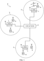
- Figure 1 provides a schematic diagram illustrating some basic functionality of a mobile telecommunications network / system 6 operating generally in accordance with LTE principles, but which may also support other radio access technologies, and which may be adapted to implement embodiments of the disclosure as described herein.
- Various elements of Figure 1 and certain aspects of their respective modes of operation are well-known and defined in the relevant standards administered by the 3GPP (RTM) body, and also described in many books on the subject, for example, Holma H. and Toskala A [1].
- the network 6 includes a plurality of base stations 1 connected to a core network 2. Each base station provides a coverage area 3 (i.e. a cell) within which data can be communicated to and from communications devices 4.
- a coverage area 3 i.e. a cell
- each base station 1 is shown in Figure 1 as a single entity, the skilled person will appreciate that some of the functions of the base station may be carried out by disparate, inter-connected elements, such as antennas, remote radio heads, amplifiers, etc. Collectively, one or more base stations may form a radio access network.
- Data is transmitted from base stations 1 to communications devices 4 within their respective coverage areas 3 via a radio downlink.
- Data is transmitted from communications devices 4 to the base stations 1 via a radio uplink.
- the core network 2 routes data to and from the communications devices 4 via the respective base stations 1 and provides functions such as authentication, mobility management, charging and so on.
- Terminal devices may also be referred to as mobile stations, user equipment (UE), user terminal, mobile radio, communications device, and so forth.
- Services provided by the core network 2 may include connectivity to the internet or to external telephony services.
- the core network 2 may further track the location of the communications devices 4 so that it can efficiently contact (i.e. page) the communications devices 4 for transmitting downlink data towards the communications devices 4.
- Base stations which are an example of network infrastructure equipment, may also be referred to as transceiver stations, nodeBs, e-nodeBs, eNB, g-nodeBs, gNB and so forth.
- nodeBs nodeBs
- e-nodeBs nodeBs
- eNB nodeB
- g-nodeBs gNodeBs
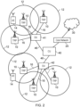
- FIG. 2 An example configuration of a wireless communications network which uses some of the terminology proposed for NR and 5G is shown in Figure 2 .
- a 3GPP Study Item (SI) on New Radio Access Technology (NR) has been defined [2].
- a plurality of transmission and reception points (TRPs) 10 are connected to distributed control units (DUs) 41, 42 by a connection interface represented as a line 16.
- DUs distributed control units
- Each of the TRPs 10 is arranged to transmit and receive signals via a wireless access interface within a radio frequency bandwidth available to the wireless communications network.
- each of the TRPs 10 forms a cell of the wireless communications network as represented by a line 12.
- Each of the distributed units 41, 42 are connected to a central unit (CU) 40 (which may be referred to as a controlling node) via an interface 46.
- the central unit 40 is then connected to the a core network 20 which may contain all other functions required to transmit data for communicating to and from the wireless communications devices and the core network 20 may be connected to other networks 30.
- the elements of the wireless access network shown in Figure 2 may operate in a similar way to corresponding elements of an LTE network as described with regard to the example of Figure 1 .
- operational aspects of the telecommunications network represented in Figure 2 and of other networks discussed herein in accordance with embodiments of the disclosure, which are not specifically described (for example in relation to specific communication protocols and physical channels for communicating between different elements) may be implemented in accordance with any known techniques, for example according to currently used approaches for implementing such operational aspects of wireless telecommunications systems, e.g. in accordance with the relevant standards.
- the TRPs 10 of Figure 2 may in part have a corresponding functionality to a base station or eNodeB of an LTE network.
- the communications devices 14 may have a functionality corresponding to the UE devices 4 known for operation with an LTE network.
- operational aspects of a new RAT network may be different to those known from LTE or other known mobile telecommunications standards.
- each of the core network component, base stations and communications devices of a new RAT network will be functionally similar to, respectively, the core network component, base stations and communications devices of an LTE wireless communications network.
- the core network 20 of the new RAT telecommunications system represented in Figure 2 may be broadly considered to correspond with the core network 2 represented in Figure 1
- the respective central units 40 and their associated distributed units / TRPs 10 may be broadly considered to provide functionality corresponding to the base stations 1 of Figure 1
- the term network infrastructure equipment / access node may be used to encompass these elements and more conventional base station type elements of wireless telecommunications systems.
- the responsibility for scheduling transmissions which are scheduled on the radio interface between the respective distributed units and the communications devices may lie with the controlling node / central unit and / or the distributed units / TRPs.
- a communications device 14 is represented in Figure 2 within the coverage area of the first communication cell 12. This communications device 14 may thus exchange signalling with the first central unit 40 in the first communication cell 212 via one of the distributed units 10 associated with the first communication cell 12.
- Figure 2 represents merely one example of a proposed architecture for a new RAT telecommunications system in which approaches in accordance with the principles described herein may be adopted, and the functionality disclosed herein may also be applied in respect of wireless telecommunications systems having different architectures.
- the network infrastructure equipment / access node may comprise a base station, such as an LTE-type base station 1 as shown in Figure 1 which is adapted to provide functionality in accordance with the principles described herein, and in other examples the network infrastructure equipment may comprise a control unit / controlling node 40 and / or a TRP 10 of the kind shown in Figure 2 which is adapted to provide functionality in accordance with the principles described herein.
- a base station such as an LTE-type base station 1 as shown in Figure 1 which is adapted to provide functionality in accordance with the principles described herein
- the network infrastructure equipment may comprise a control unit / controlling node 40 and / or a TRP 10 of the kind shown in Figure 2 which is adapted to provide functionality in accordance with the principles described herein.
- a TRP 10 as shown in Figure 2 comprises, as a simplified representation, a wireless transmitter 30, a wireless receiver 32 and a controller or controlling processor 34 which may operate to control the transmitter 30 and the wireless receiver 32 to transmit and receive radio signals to one or more UEs 14 within a cell 12 formed by the TRP 10.
- an example UE 14 is shown to include a corresponding transmitter 49, a receiver 48 and a controller 44 which is configured to control the transmitter 49 and the receiver 48 to transmit signals representing uplink data to the wireless communications network via the wireless access interface formed by the TRP 10 and to receive downlink data as signals transmitted by the transmitter 30 and received by the receiver 48 in accordance with the conventional operation.
- the transmitters 30, 49 and the receivers 32, 48 may include radio frequency filters and amplifiers as well as signal processing components and devices in order to transmit and receive radio signals in accordance for example with the 5G standard.
- the controllers 34, 44 may be, for example, a microprocessor, a CPU, or a dedicated chipset, etc., configured to carry out instructions which are stored on a computer readable medium, such as a nonvolatile memory.
- a computer readable medium such as a nonvolatile memory.
- the processing steps described herein may be carried out by, for example, a microprocessor in conjunction with a random access memory, operating according to instructions stored on a computer readable medium.
- the TRP 10 also includes a network interface 50 which connects to the DU 42 via a physical interface 16.
- the network interface 50 therefore provides a communication link for data and signalling traffic from the TRP 10 via the DU 42 and the CU 40 to the core network 20.
- the interface 46 between the DU 42 and the CU 40 is known as the F1 interface which can be a physical or a logical interface.
- the F1 interface 46 between CU and DU may operate in accordance with specifications 3GPP TS 38.470 and 3GPP TS 38.473, and may be formed from a fibre optic or other wired high bandwidth connection.
- the connection 16 from the TRP 10 to the DU 42 is via fibre optic.
- the connection to the core network can be generally referred to as a backhaul comprising the interface 16 from the network interface 50 of the TRP10 to the DU 42 and the F1 interface 46 from the DU 42 to the CU 40.
- Example embodiments of the present technique which can be formed from a wireless communications network corresponding to that shown in Figures 1 or 2 is shown in Figure 4.
- Figure 4 provides an example in which cells of a wireless communications network are formed from infrastructure equipment which are provided with an Integrated Access and Backhaul (IAB) capability.
- the wireless communications network 100 comprises the core network 20 and a first, a second, a third and a fourth communications device (respectively 101, 102, 103 and 104) which may broadly correspond to the communications devices 4, 14 described above.
- the wireless communications network 100 comprises a radio access network, comprising a first infrastructure equipment 110, a second infrastructure equipment 111, a third infrastructure equipment 112, and a fourth infrastructure equipment 113.
- Each of the infrastructure equipment provides a coverage area (i.e. a cell, not shown in Figure 4 ) within which data can be communicated to and from the communications devices 101-104.
- the fourth infrastructure equipment 113 provides a cell in which the third and fourth communications devices 103 and 104 may obtain service.
- Data is transmitted from the fourth infrastructure equipment 113 to the fourth communications device 104 within its respective coverage area (not shown) via a radio downlink.
- Data is transmitted from the fourth communications device 104 to the fourth infrastructure equipment 113 via a radio uplink.
- the infrastructure equipment 110-113 in Figure 4 may correspond broadly to the TRPs 10 of Figure 2 and Figure 3 .
- the first infrastructure equipment 110 in Figure 4 is connected to the core network 20 by means of one or a sequence of physical connections.
- the first infrastructure equipment 110 may comprise the TRP 10 (having the physical connection 16 to the DU 42) in combination with the DU 42 (having a physical connection to the CU 40 by means of the F1 interface 46) and the CU 40 (being connected by means of a physical connection to the core network 20).
- the second infrastructure equipment 111 there is no physical connection between any of the second infrastructure equipment 111, the third infrastructure equipment 112, and the fourth infrastructure equipment 113 and the core network 20.
- data received from a communications device i.e. uplink data
- data for transmission to a communications device i.e. downlink data
- infrastructure equipment such as the first infrastructure equipment 110 which has a physical connection to the core network 20, even if the communications device is not currently served by the first infrastructure equipment 110 but is, for example, in the case of the wireless communications device 104, served by the fourth infrastructure equipment 113.
- the second, third and fourth infrastructure equipment 111-113 in Figure 4 may each comprise a TRP, broadly similar in functionality to the TRPs 10 of Figure 2 .
- one or more of the second to fourth infrastructure equipment 111-113 in Figure 4 may further comprise a DU 42, and in some embodiments of the present technique, one or more of the second to fourth infrastructure equipment 110-113 may comprise a DU and a CU.
- the CU 40 associated with the first infrastructure equipment 110 may perform the function of a CU not only in respect of the first infrastructure equipment 110, but also in respect of one or more of the second, the third and the fourth infrastructure equipment 111-113.
- a route is determined by any suitable means, with one end of the route being an infrastructure equipment physically connected to a core network and by which uplink and downlink traffic is routed to or from the core network.
- 'node' is used to refer to an entity which forms a part of a route for the transmission of the uplink data or the downlink data.
- An infrastructure equipment which is physically connected to the core network and operated in accordance with an example embodiment may provide communications resources to other infrastructure equipment and so is referred to as a ⁇ donor node'.
- An infrastructure equipment which acts as an intermediate node i.e. one which forms a part of the route but is not acting as a donor node
- the relay node at the end of the route which is the infrastructure equipment controlling the cell in which the communications device is obtaining service is referred to as an ⁇ end node'.
- each of the first to fourth infrastructure equipment 110-113 may therefore function as nodes.
- a route for the transmission of uplink data from the fourth communications device 104 may consist of the fourth infrastructure equipment 113 (acting as the end node), the third infrastructure equipment 112 (acting as a relay node), and the first infrastructure equipment 110 (acting as the donor node).
- the first infrastructure 110 being connected to the core network 20, transmits the uplink data to the core network 20
- the infrastructure equipment 110 is referred to below as the ⁇ donor node'
- the first infrastructure equipment 111 is referred to below as ⁇ Node 1'
- the second infrastructure equipment 112 is referred to below as ⁇ Node 2'
- the third infrastructure equipment 113 is referred to below as ⁇ Node 3'.
- ⁇ upstream node' is used to refer to a node acting as a relay node or a donor node in a route, which is a next hop when used for the transmission of data via that route from a wireless communications device to a core network.
- 'downstream node' is used to refer to a relay node from which uplink data is received for transmission to a core network. For example, if uplink data is transmitted via a route comprising (in order) the Node 3 113, the Node 1 111 and the donor node 110, then the donor node 110 is an upstream node with respect to the Node 1 111, and the Node 3 113 is a downstream node with respect to the Node 1 111.
- More than one route may be used for the transmission of the uplink data from a given communications device; this is referred to herein as 'multi-connectivity'.
- the uplink data transmitted by the wireless communications device 104 may be transmitted either via the Node 3 113 and the Node 2 112 to the donor node 110, or via the Node 3 113 and the Node 1 111 to the donor node 110.
- each of the nodes is an infrastructure equipment; the present disclosure is not so limited.
- a node may comprise at least a transmitter, a receiver and a controller.
- the functionality of a node may be carried out by a communications device, which may be the communications device 4 (of Figure 1 ) or 14 (of Figure 2 ), adapted accordingly.
- a route may comprise one or more communications devices.
- a route may consist of only a plurality of infrastructure equipment.
- an infrastructure equipment acting as a node may not provide a wireless access interface for the transmission of data to or by a communications device other than as part of an intermediate transmission along a route.
- a route is defined considering a wireless communications device (such as the wireless communications device 104) as the start of a route.
- a route is considered to start at an infrastructure equipment which provides a wireless access interface for the transmission of the uplink data by a wireless communications device.
- the nodes In order for the uplink data to be successfully transmitted from one node in a route to an adjacent node, the nodes must be within a wireless communications range. However, in order to ensure reliable reception of the uplink data, interference caused by transmissions by other nodes or by other communications devices which are within wireless communications range of the receiving node must be minimized. In particular, it is preferable that transmissions of the uplink data from one node to another do not coincide with transmissions of other uplink data by another node, if the two transmissions could result in a high probability of one or both of the transmissions being incorrectly or unsuccessfully received (for example, because they overlap in both time and frequency, or because simultaneous transmission and reception by a single node is not practical).
- the method comprises determining an allocation of a first set of communications resources by the infrastructure equipment acting as a first relay node for another infrastructure equipment acting as a second relay node, the communications resources for transmitting uplink data from a first communications device to an infrastructure equipment connected to a core network part of the wireless communications network acting as a donor node.
- the allocation of the first set of communications resources for the other infrastructure equipment acting as the second relay node is based upon a donor set of communications resources allocated by the donor node for communicating the uplink data from the first communications device to the donor node via the infrastructure equipment acting as the first relay node.
- the method further comprises transmitting an indication of the first set of communications resources to the other infrastructure equipment acting as the second relay node, receiving the uplink data from the first communications device, the uplink data having been transmitted by the other infrastructure equipment acting as the second relay node using the first set of communications resources and transmitting the uplink data from the first communications device using a second set of communications resources different from the first set of communications resources.
- Each of the first infrastructure equipment acting as the donor node 110 and the second to fourth infrastructure equipment acting as the Nodes 1-3 111-113 may communicate with one or more other nodes by means of an inter-node wireless communications link, which may also be referred to as a wireless backhaul communications links.
- an inter-node wireless communications link which may also be referred to as a wireless backhaul communications links.
- Figure 4 illustrates four inter-node wireless communications links 130, 132, 134, 136.
- Each of the inter-node wireless communications links 130, 132, 134, 136 may be provided by means of a respective wireless access interface.
- two or more of the inter-node wireless communications links 130, 132, 134, 136 may be provided by means of a common wireless access interface and in particular, in some embodiments, all of the inter-node wireless communications links 130, 132, 134, 136 are provided by a shared wireless access interface.
- a wireless access interface which provides an inter-node wireless communications link may also be used for communications between an infrastructure equipment (which may be a node) and a communications device which is served by the infrastructure equipment.
- the wireless communications device 104 may communicate with the infrastructure equipment Node 3 113 using the wireless access interface which provides the inter-node wireless communications link 134 connecting the Node 3 113 and the Node 2 112.
- the wireless access interface(s) providing the inter-node wireless communications links 130, 132, 134, 136 may operate according to any appropriate specifications and techniques.
- a wireless access interface used for the transmission of data from one node to another uses a first technique and a wireless access interface used for the transmission of data between an infrastructure equipment acting as a node and a communications device may use a second technique different from the first.
- the wireless access interface(s) used for the transmission of data from one node to another and the wireless access interface(s) used for the transmission of data between an infrastructure equipment and a communications device use the same technique.
- wireless access interface standards include the third generation partnership project (3GPP)-specified general packet radio service (GPRS)/enhanced data rates for global system for mobile communications (GSM) evolution (EDGE) ("2G”), wideband code division multiple access (WCDMA) universal mobile telecommunications system (UMTS) and related standards such as HSPA (high speed packet access) and HSPA+ (“3G”), LTE (long term evolution) and related standards including LTE-A (“4G”), and new radio access technology (NR) (“5G”).
- 3GPP third generation partnership project
- GPRS general packet radio service
- EDGE global system for mobile communications
- WCDMA wideband code division multiple access
- UMTS universal mobile telecommunications system
- HSPA high speed packet access
- HSPA+ high speed packet access
- LTE long term evolution
- 4G long term evolution
- NR new radio access technology
- TDMA time division multiple access
- FDMA frequency division multiple access
- OFDMA orthogonal frequency division multiple access
- SC-FDMA single carrier frequency division multiple access
- CDMA code division multiple access CDMA.
- Duplexing i.e. the transmission over a wireless link in two directions
- FDD frequency division duplexing
- TDD time division duplexing
- two or more of the inter-node wireless communications links 130, 132, 134, 136 may share communications resources. This may be because two or more of the inter-node wireless communications links 130, 132, 134, 136 are provided by means of a single wireless access interface or because two or more of the inter-node wireless communications links 130, 132, 134, 136 nevertheless operate simultaneously using a common range of frequencies.
- a physical interface 46 may connect a DU 41 and a CU 40.
- one DU 41 may be associated with the donor node 110, and a different DU 41 may be associated with another infrastructure equipment, such as for example the Node 1 111.
- a logical F1 connection may be realised between a CU 40 associated with an donor node and a DU 41 associated with the Node 1 111 by means of a combination of the physical interface 46 connecting the CU 40 to the DU 41 associated with the donor node 110, the interface 16 connecting the DU 41 associated with the donor node 110 with the TRP 10 associated with the donor node 110, and one or more of the inter-node wireless communications links 130, 132, 134, 136.
- a wireless access interface may provide communications resources which can be allocated by any appropriate method to an individual transmission or a group of transmissions.
- the communications resources may be characterised by one or more of a time period, a range of frequencies and a code sequence.
- transmissions using communications resources which are mutually orthogonal may be successfully distinguished from each other by appropriate signal processing techniques at the receiving entity.
- a communications resource allocation may therefore comprise a set of communications resources for a particular purpose.
- the communications resource allocation may be characterised in any manner appropriate to the technology and/or standard used for the corresponding wireless access interface.
- a communications resource allocation in an OFDM-based wireless access interface may be characterised by a time period (which may be expressed in terms of OFDM symbols) and one or more sub-carriers in the frequency domain.
- the communications resources may comprise a bandwidth part, that is to say, a contiguous portion of the frequency resources which are assigned for the exclusive use of the operator of the wireless communications network, which may be allocated for an uninterrupted time period.
- a communications resource allocation may comprise a periodic repetition.
- Tperiod the periodicity of the allocation
- A is an offset value. The number of repetitions or the duration for which the allocation remains valid may be limited.
- the communications resources are allocated to the infrastructure equipment 110-113 within the wireless communications network 100 for the transmission of the uplink data originating at one or more of the mobile communications devices 101-104.
- uplink data refers to data which originates at a mobile communications device and is transmitted via a wireless access interface provided by an infrastructure equipment controlling a cell in which the mobile communications device is obtaining service. The uplink data is then transmitted, directly or indirectly, to a core network.
- the uplink data originating at the fourth communications device 104 is transmitted initially to the Node 3 113, via the wireless access interface provided by the Node 3 113, and is subsequently transmitted via the donor node 110 to the core network 20.
- the ultimate destination of the uplink data may be within the core network 20, may be another mobile communications device, or may be any other destination which is reachable via the core network 20 (e.g. via the public switched telephony network or via the internet).
- the communications resources allocated to each infrastructure equipment for the uplink data transmission are a subset of communications resources (referred to as donor resources) identified by the infrastructure equipment 110 acting as the donor node.
- the communications resource allocations are transmitted through the radio access network in a 'downstream' direction, that is, away from the donor node.
- the Node 3 113 may transmit the uplink data to the donor node 111 via either, or both of, the Node 1 111 and the Node 2 112. In such circumstances, the Node 3 113 may receive communications resource allocations from either or both of the Node 1 111 and the Node 2 112.
- Figure 5 illustrates signalling between infrastructure equipment by which the communications resource allocations may be transmitted.
- a process of transmitting the uplink data starts (not illustrated) with the determination (not illustrated) by the donor node 110 of the route or routes by which the uplink data, which originates at the wireless communications device 104, is to be transmitted.
- the route may start at the wireless communications device 104, or at the particular infrastructure node 113 controlling the cell in which the wireless communications device 104 is being served.
- the donor node 110 determines the donor resources to be used within the radio access network for the transmission of the uplink data.
- the donor resources may be the communications resources to be used collectively by the nodes which are in the route or routes (e.g. the Node 1 111, the Node 2 112 and the Node 3 113, if they each form a node in the route or routes).
- the donor node 110 then transmits a first communications resource allocation indication 301 indicating communications resources to the Node 2 112.
- the indicated communications resources are described in more detail below.
- the Node 2 112 determines which of the indicated communications resources are to be used for (i.e. are allocated for) the transmission of the uplink data from the Node 2 112 to the donor node 110.
- the Node 2 112 transmits to the Node 3 113 a second communications resource allocation indication 305 indicating the communications resources allocated for the transmission of the uplink data from the Node 3 113 to the Node 2 112.
- a third communications resource allocation indication 303 of an allocation of communications resources may be transmitted by the donor node 110 to the Node 1 111. Then, based on the received third communications resource allocation indication 303, the Node 1 111 determines the communications resources which are allocated for the transmission of the uplink data from the Node 1 111 to the donor node 110. Subsequently, the Node 1 111 transmits to the Node 3 113 an indication 307 of the communications resources allocated for the transmission of the uplink data from the Node 3 113 to the Node 2 111.
- the communications resource allocation indications 301, 303, 305, 307 may be transmitted by means of dedicated radio resource control (RRC) signalling or by means of transmissions (such as Downlink Control Information (DCI) messages) on a physical downlink control channel (PDCCH).
- RRC dedicated radio resource control
- DCI Downlink Control Information
- a format for the messages may provide for the indication of the communications resources and the node or interface to which they are allocated.
- each of the indications in Figure 5 are shown as a single transmission, the techniques described herein are not so limited.
- an allocation of the communications resources comprises a plurality of contiguous regions (in both the time and frequency domains)
- each contiguous region may be indicated in a separate transmission.
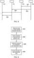
- Figure 6 is a flow chart of a process which may be carried out by a node (which, in the present description may be an infrastructure equipment such as the infrastructure equipment acting as the Node 1 111), according to an example embodiment of the present technique.
- a node which, in the present description may be an infrastructure equipment such as the infrastructure equipment acting as the Node 1 111, according to an example embodiment of the present technique.
- the process in Figure 6 starts at step 402, in which the infrastructure equipment 111 determines a route or routes requiring an allocation of the communications resources.
- the infrastructure equipment 111 receives an indication of a set of the communications resources from an upstream node.
- the upstream node may be a donor node such as the donor node 110.
- the infrastructure equipment 111 determines the communications resources to be allocated to each downstream node (for example, to the infrastructure equipment acting as the Node 3 113).
- the infrastructure equipment 111 may also determine the communications resources to be used for its own transmissions of the uplink data according to the route.
- step 408 the infrastructure equipment 111 transmits to each of its downstream nodes (in the example, the Node 3 113) an indication of the communications resources for the transmission of the uplink data.
- step 404 may instead comprise determining the donor resources, from which all of the communications resources to be allocated for the route or routes are to be selected.
- the communications resources which are allocated in step 406 may be based on the donor resources allocated by the donor node.
- the donor resources are known to each infrastructure equipment carrying out the process illustrated in Figure 6 .
- a centralised approach to communications resource allocation may be taken. That is, the communications resource allocation for each of the nodes 111-113, or for each of the inter-node wireless communications links 130, 132, 134, 136, is determined by the donor node 110. As such, each communications resource allocation indication transmitted by the donor node 110 to a recipient infrastructure equipment contains an indication of the communications resources to be used by (or available for) each downstream node (including the recipient infrastructure equipment) which forms a hop in a route which also includes the recipient infrastructure equipment.
- the Node 3 113 has two routes for the uplink data: Node 3 - Node 2 - Donor Node, and Node 3 - Node 1 - Donor Node.
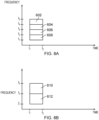
- the donor node 110 may first determine the donor resources as being those bounded by the times t1 and t2, and by the frequencies f1 and f5. The donor node 110 may then allocate the communications resources from the donor resources as follows:
- Each of the messages 301 and 303 transmitted by the donor node to the Node 2 and the Node 1 respectively indicate the communications resource allocations for both the respective recipient node (Node 2 or Node 1) and for the Node 3 for its transmissions to the Node2 and the Node 1 respectively.
- the message 301 from the donor node 110 to the Node 2 112 indicates that the first communications resources 608 and the second communications resources 606 are allocated for the inter-node wireless communications links 134 and 132 respectively.
- the message 302 from the donor node 110 to the Node 1 111 indicates that the third communications resources 604 and fourth communications resources 602 are allocated for the inter-node wireless communications links 136 and 130 respectively.
- the message 305 from the Node 2 112 to the Node 3 113 indicates that the first communications resources 608 are allocated for the inter-node wireless communications link 134.
- An inter-node wireless communications link may be identified in the signalling by reference to an identifier of the downstream node; for example, the inter-node wireless communications link 130 may be identified by a reference to an identifier of the Node 1 111.
- each node forwards only an indication of the communications resources which are allocated to downstream nodes, thereby ensuring that the allocation messages are compact. In some embodiments, each node forwards indications of communications resources which are allocated to downstream nodes and to one or more of the forwarding node and its upstream nodes. As such, in some embodiments, nodes may be aware of only their own allocations and those of their downstream nodes; in other embodiments, nodes may be aware of allocations of additional nodes in the topology.
- Some infrastructure equipment may have downstream nodes which does not form a part of any route; for example, in Figure 4 , the Node 2 112 is downstream of the donor node 110, however no communications devices are being served by the Node 2 112 and it may have been determined that the only route for the uplink data from the Node 3 113 to the donor node is via the Node 1 111.
- the upstream node (the donor node 110 in this example) may transmit communications resource allocation messages only to those nodes (infrastructure equipment) which form part of a route for the uplink data.
- the upstream node (the donor node 110 in this example) transmits communications resource allocation messages only to a downstream node (infrastructure equipment) if the inter-node wireless communications link between the downstream node and the upstream node forms part of a route for the uplink data.
- the centralised communications resource allocations are communicated to the various infrastructure equipment by means of broadcast transmissions by the donor node. Additionally or alternatively, subsequent transmissions by downstream nodes may be broadcast.
- a physical resource to broadcast the control data indicating the communications resource allocations can be pre-determined in specification. In order to avoid unnecessary transmissions, a maximum number of onward (i.e. forwarded) retransmissions may be specified, either in an appropriate specification, or by the donor node.
- the allocation of communications resources to each node in the topology may be determined by the donor node.
- each node (other than the donor node) which is on a route for the transmission of the uplink data receives an allocation of communications resources from its immediate upstream node(s).
- the receiving node then partitions the indicated communications resources and allocates a portion for its own use, and a portion for the use of each node which is immediately downstream of it within the topology. An indication of the allocated portions of the communications resources are then transmitted to the respective downstream nodes. The process repeats until all nodes which are on a route for the uplink data have received an allocation of communications resources.
- the receiving node may allocate all or only a portion of the indicated communications resources.
- a node may allocate all of the indicated communications resources for its own use.
- the donor node 110 having by definition no upstream node, determines a communications resource allocation for each downstream node i.e. those which are adjacent to it in the route topology. In other words, the donor node 110 determines a communications resource allocation of communications resources for each of the Node 1 111 and the Node 2 112 for which the donor node 110 is the immediate next-hop on a route for the uplink data from one or more communications devices.
- the donor node 110 may allocate in message 303 communications resources 610 (illustrated in Figure 8B , bounded by the times t1 and t2, and by frequencies f3 and f5) for the Node 1 111 and, in message 301, communications resources 612 bounded by the times t1 and t2 and by frequencies f1 and f3 for the Node 2 112.
- communications resources 610 illustrated in Figure 8B , bounded by the times t1 and t2, and by frequencies f3 and f5
- communications resources 612 bounded by the times t1 and t2 and by frequencies f1 and f3 for the Node 2 112.
- the Node 2 112 may partition the communications resources 612, allocating those resources between frequencies f2 and f3 (i.e. communications resources 606 of Figure 8A ) for its own use in transmitting the uplink data towards the donor node 210, and allocating those resources between the frequencies f1 and f2 (i.e. communications resources 608 of Figure 8A ) to the Node 3 113, for the transmission of the uplink data by the Node 3 113 to the Node 2 112 or, if the Node 3 113 had further downstream nodes, for the allocation by the Node 3 113 to those downstream nodes.
- frequencies f2 and f3 i.e. communications resources 606 of Figure 8A
- the Node 2 112 may then transmit in message 305 an indication of the allocation of the communications resources 608 to the Node 3 113.
- the Node 1 111 may apportion the communications resources 610 and may transmit in message 307 an indication of the communications resources which it has allocated to the Node 3 113 or infrastructure equipment downstream of the Node 3.
- any of the allocation of communications resources and the donor resources may comprise a plurality of disjoint communications resources, and in particular, may repeat in time and/or frequency.
- various techniques within the scope of the present disclosure may be used to allocate communications resources from an upstream node to a downstream node.
- communications resources may be allocated in response to the receipt of an allocation of communications resources from an upstream node.
- communications resources may be available in advance of when the uplink data is to be transmitted.
- an infrastructure node receives the uplink data, originating from a wireless communications device and for transmission to the core network via an infrastructure equipment acting as a donor node
- the infrastructure node receiving the uplink data may transmit it using the allocated communications resources, without needing to request communications resources from an upstream node.
- the allocated communications resources provide a small amount of bandwidth, which may be increased in response to their use.
- communications resources may be allocated on demand, i.e. in response to a request received from the downstream node.
- a downstream node may transmit a scheduling request (SR) to the allocating (upstream) node.
- the upstream node may transmit an indication of communications resources allocated for a transmission of a buffer status report (BSR) by the requesting infrastructure equipment.
- BSR buffer status report
- the requesting infrastructure equipment may transmit a BSR indicating one or more of a total quantity of the uplink data to be transmitted, an amount of the uplink data currently stored in a buffer of the infrastructure equipment, and a bandwidth amount.
- the allocating infrastructure equipment may transmit (e.g. as described above in respect of Figure 5 ) an indication of communications resources allocated for the transmission of the uplink data by the requesting infrastructure equipment.
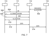
- the Node 2 112 receives an allocation of communications resources 502 from an upstream node, which may be the donor node 110.
- a downstream node which may be the Node 3 113 determines that communications resources for the transmission of the uplink data are required from the Node 2 112, and the Node 3 113 transmits a scheduling request 504 to the Node 2 112.
- the Node 2 112 responds by allocating communications resources for the transmission of an indication of a quantity of communications resources being requested, which may be in the form of a buffer status report (BSR).
- BSR buffer status report
- the Node 3 113 uses the communications resources indicated in the message 506, the Node 3 113 transmits the indication of the quantity of communications resources being requested (e.g. in the form of a BSR) in a message 508. The Node 2 112 then allocates the communications resources for the transmission of the uplink data and indicates these to the Node 3 113 in message 510.
- the indication of the quantity of communications resources being requested e.g. in the form of a BSR
- the Node 3 113 then transmits the uplink data using the communications resources indicated in message 510.
- the transmission 512 may be a single transmission or a plurality of transmissions, according to the communications resources allocated and the quantity of the uplink data to be transmitted.
- the Node 2 112 transmits the uplink data 514 to its upstream node 110.
- the Node 2 112 may employ a similar procedure as described above (i.e. including a sequence of messages similar to the messages 504, 506, 508, 510 sent between the Node 2 112 and the Node 3 113) to obtain communications resources for the transmission 514 of the uplink data.
- the requesting infrastructure equipment may initiate a random access channel (RACH) procedure by transmitting a random access request message on a random access channel.
- RACH random access channel
- the allocating infrastructure equipment allocates frequent communications resources for the transmission of scheduling requests.
- an infrastructure equipment may allocate a portion of the communications resources indicated in a message received from an upstream node for contention-based access by one or more downstream nodes. For example, in response to receiving the indication 303 of the communications resources allocated by the donor node 110, the Node 1 111 may transmit the indication 307 downstream to the Node 3 113, the indication 307 identifying communications resources allocated for contention-based uplink access.
- the indication 307 identifying the communications resources for contention-based access is transmitted as part of broadcast system information.
- the communications resources for the contention-based access may be used by both infrastructure equipment and by wireless communications devices.
- a device which determines that it has uplink data for transmission to the core network, transmits using the communications resources allocated for contention-based access either a request for dedicated communications resources for the subsequent transmission of the uplink data, or some or all of the uplink data.
- the receiving infrastructure equipment may allocate dedicated communications resources for subsequent transmission of the uplink data by the device. In some embodiments, in response to successfully decoding two or more transmissions sent simultaneously (or at least overlapping in time) by devices using the contention-based communications resources, the receiving infrastructure equipment may allocate dedicated communications resources for subsequent transmission of the uplink data by each of the devices.
- the communications resource allocations may be adapted over time.
- the donor node 110 may increase or decrease the quantity of communications resources allocated to a particular node or route in response to one or more of traffic demand, network load, and radio conditions associated with the wireless access interfaces making up the route.
- any of the donor node 110 or the relay nodes (such as the Node 1 111 or the Node 2 112) which allocate resources to downstream nodes may increase or decrease the quantity of communications resources allocated to a particular node or route in response to one or more of traffic demand, network load, and radio conditions associated with the wireless access interfaces making up the route.
- an infrastructure equipment may transmit the uplink data towards the core network using allocated communications resources, after it has received an indication of the allocated communications resources.
- an infrastructure equipment may transmit the uplink data towards the core network using allocated communications resources which have been activated.
- the uplink data may be transmitted by an infrastructure equipment only after it has received both an indication of the allocated communications resources and an indication that some or all of the allocated communications resources have been activated.
- the indication that some or all of the allocated communications resources have been activated may comprise a medium access control (MAC) control element (CE).
- the indication that some or all of the allocated communications resources have been activated may comprise downlink control information (DCI) transmitted on a physical downlink control channel.
- DCI downlink control information
- an infrastructure equipment may transmit the uplink data towards the core network using communications resources, only after it has received both an indication of the allocated communications resources and an indication that some or all of the allocated communications resources have been activated and while no indication that the activated communications resources have been deactivated has been received.
- communications resources that have been allocated but are not activated (or have since been deactivated) may be used for the transmission of the uplink data by a wireless communications device.
- an allocation of communications resources comprises a dynamic uplink grant of the communications resources to be used for the transmission of the uplink data via a particular route.
- each route is dynamically allocated communications resources by means of DCI. If the amount of dynamically allocated communications resources exceeds the amount needed to transmit the uplink data, an infrastructure node may indicate this by, in a portion of the communications resources, transmitting one or more MAC protocol data units (PDUs) comprising padding or not transmitting at all.
- PDUs MAC protocol data units
- an infrastructure node may transmit an indication of this in a portion of the allocated communications resources.
- an indication may comprise a buffer status report or a signal transmitted in uplink control information (UCI).
- UCI uplink control information
- an upstream node (which may be acting as a donor node) may adjust the dynamically allocated communications resources accordingly.
- an infrastructure equipment acting as a relay node may have multiple upstream node from which it is receiving an allocation of communications resources.
- the Node 3 113 may receive allocations from the Node 2 112 and from the Node 1 111.
- a relay node may receive allocations for communications resources for the transmission of the uplink data to two or more upstream node.
- the relay node may determine a quantity or proportion of the uplink data to transmit using each of the allocations based on one or more of radio conditions applicable to the communications link between the relay node and each of the upstream node and a congestion level (which may be based on a determination of a delay experienced in respect of the uplink data).
- a means is provided for an infrastructure equipment acting as a relay node to request an allocation of communications resources from an infrastructure equipment (referred to herein as a candidate infrastructure equipment) which is not an upstream node of the relay node on an existing route.
- an infrastructure equipment referred to herein as a candidate infrastructure equipment
- the infrastructure equipment acting as a relay node may receive from an upstream node a communications resource for communicating with the candidate infrastructure equipment (these resources are referred to as ⁇ candidate request communications resources').
- the candidate request communications resources may comprise, for example, a reserved preamble for use on a random access channel or an uplink grant of communications resources for the transmission of a request to the candidate infrastructure equipment.
- the resource may comprise a bandwidth part (BWP).
- the candidate request communications resources may be dedicated (i.e. for the sole use of the infrastructure equipment) or may be shared amongst two or more infrastructure equipment and thus be accessed in a contention-based manner.
- An appropriate format associated with the candidate request communications resources may be defined or configured, for example a format for a transmission using a physical uplink shared channel (PUSCH) or a physical uplink control channel (PUCCH).
- PUSCH physical uplink shared channel
- PUCCH physical uplink control channel
- the candidate request communications resources may be shared, it may be restricted to infrastructure equipment which are acting as relay nodes.
- the candidate request communications resources may be valid for a duration such that the infrastructure equipment may use the resource at a time of its determination, or with a low delay.
- An infrastructure equipment acting as a relay node may use the candidate request communications resources to initiate a procedure to request the allocation of communications resources for the transmission of the uplink data via the candidate infrastructure equipment, for example in response to a determination that radio conditions and/or a traffic load on an existing route are, or are likely to become, unsuitable for the transmission of the uplink data.
- the candidate infrastructure equipment may initiate a procedure to activate a new route in which the candidate infrastructure equipment acts as a relay node for the transmission of the uplink data.
- the candidate infrastructure equipment may allocate communications resources to the infrastructure equipment for the transmission of the uplink data to the candidate infrastructure equipment.
- the Node 3 113 of Figure 4 may currently use a route via the Node 1 111 for the transmission of the uplink data to the donor node 110.
- the Node 1 111 may transmit to the Node 3 113 an indication of candidate request communications resources which may be used by the Node 3 113 to request communications resources from the Node 2 112 acting as the candidate infrastructure equipment.
- the Node 3 113 may subsequently determine that radio conditions applicable to transmissions from the Node 3 113 to the Node 1 111 mean that the route via the Node 1 111 is unsuitable for the transmission of the uplink data. Based on this determination, the Node 3 113 initiates a request for resources from the candidate infrastructure equipment (i.e. the Node 2 112) using the candidate request communications resources previously indicated by the Node 1 111.
- the candidate infrastructure equipment i.e. the Node 2 112
- a request for a modification of a route or a request (such as a scheduling request) for an allocation of communications resources for the transmission of the uplink data to a candidate infrastructure equipment may be transmitted to an upstream node.
- this request may be transmitted to the upstream node using communications resources which have been allocated for the purpose of transmitting the uplink data to the upstream node. This may be referred to as ⁇ uplink pre-emption'.
- the upstream node may forward this request along the route towards the donor node. This forwarding may also make use of uplink pre-emption. Accordingly, the donor node may receive the request and, in response, may allocate communications resources for the transmission of the uplink data to the candidate infrastructure equipment, according to any of the example techniques disclosed herein. Subsequently, the infrastructure node which initiated the request may transmit the uplink data using the newly allocated communications resources, via the candidate infrastructure equipment.
- the communications resources are allocated from the donor resources for the transmission of the uplink data from the Node 3 113 to the donor node 110 via the Node 1 111. Subsequently, the uplink data is transmitted using the allocated communications resources (706, 708).
- the Node 3 113 transmits a request 710 for communications resources for the transmission of the uplink data via the Node 2 112, the Node 2 112 acting as a candidate node.
- This request is transmitted using the communications resources allocated at 704 i.e. resources which have been allocated for the transmission of the uplink data.
- the Node 3 113 pre-empts the uplink data with the request.
- the request 710 is received by the upstream node i.e. the Node 1 111.
- the Node 1 forwards (712) the request along the route towards the donor node.
- the donor node 110 is thus the recipient of the forwarded request 712. This forwarding may also make use of uplink pre-emption of the communications resources allocated by message 702. Accordingly, the donor node 110 receives the request and, in response, allocates the communications resources for the transmission of the uplink data via the candidate infrastructure equipment the Node 2 112.
- Indications transmitted from the donor node 110 to the Node 2 112 (714) and from the Node 2 112 to the Node 3 113 (716) thus provide for the allocation of the communications resources for the transmission of the uplink data along a route comprising (in order) the Node 3 113, the Node 2 112, and the donor node 110. Accordingly, the uplink data is transmitted via this route (718, 720).
- infrastructure equipment and/or communications devices as herein defined may be further defined in accordance with the various arrangements and embodiments discussed in the preceding paragraphs. It would be further appreciated by those skilled in the art that such infrastructure equipment and communications devices as herein defined and described may form part of communications systems other than those defined by the present invention.
Landscapes
- Engineering & Computer Science (AREA)
- Computer Networks & Wireless Communication (AREA)
- Signal Processing (AREA)
- Quality & Reliability (AREA)
- Mobile Radio Communication Systems (AREA)
- Radio Relay Systems (AREA)
Applications Claiming Priority (3)
| Application Number | Priority Date | Filing Date | Title |
|---|---|---|---|
| EP18164439 | 2018-03-27 | ||
| EP19708572.3A EP3759961B1 (de) | 2018-03-27 | 2019-03-11 | Verfahren und infrastrukturausrüstung |
| PCT/EP2019/056003 WO2019185340A1 (en) | 2018-03-27 | 2019-03-11 | Methods and infrastructure equipment |
Related Parent Applications (2)
| Application Number | Title | Priority Date | Filing Date |
|---|---|---|---|
| EP19708572.3A Division-Into EP3759961B1 (de) | 2018-03-27 | 2019-03-11 | Verfahren und infrastrukturausrüstung |
| EP19708572.3A Division EP3759961B1 (de) | 2018-03-27 | 2019-03-11 | Verfahren und infrastrukturausrüstung |
Publications (2)
| Publication Number | Publication Date |
|---|---|
| EP4429384A2 true EP4429384A2 (de) | 2024-09-11 |
| EP4429384A3 EP4429384A3 (de) | 2024-12-11 |
Family
ID=61873294
Family Applications (2)
| Application Number | Title | Priority Date | Filing Date |
|---|---|---|---|
| EP24190274.1A Pending EP4429384A3 (de) | 2018-03-27 | 2019-03-11 | Verfahren und infrastrukturausrüstung |
| EP19708572.3A Active EP3759961B1 (de) | 2018-03-27 | 2019-03-11 | Verfahren und infrastrukturausrüstung |
Family Applications After (1)
| Application Number | Title | Priority Date | Filing Date |
|---|---|---|---|
| EP19708572.3A Active EP3759961B1 (de) | 2018-03-27 | 2019-03-11 | Verfahren und infrastrukturausrüstung |
Country Status (4)
| Country | Link |
|---|---|
| US (2) | US11496927B2 (de) |
| EP (2) | EP4429384A3 (de) |
| CN (2) | CN119095117A (de) |
| WO (1) | WO2019185340A1 (de) |
Families Citing this family (5)
| Publication number | Priority date | Publication date | Assignee | Title |
|---|---|---|---|---|
| KR20200013576A (ko) * | 2018-07-30 | 2020-02-07 | 주식회사 케이티 | 5g 무선 릴레이를 위한 흐름 제어 방법 및 장치 |
| CN119545424A (zh) * | 2018-08-09 | 2025-02-28 | 苹果公司 | 用于集成接入和回程网络中的上行链路流量的流控制 |
| US12082220B2 (en) * | 2019-07-31 | 2024-09-03 | Qualcomm Incorporated | Techniques for connecting user equipment with multiple base stations through a wireless repeater |
| CN115428517A (zh) * | 2020-04-24 | 2022-12-02 | 联想(北京)有限公司 | 用于iab网络中的父链路与子链路之间的动态fdm的方法及设备 |
| US20220022214A1 (en) * | 2020-07-20 | 2022-01-20 | Qualcomm Incorporated | Scheduling bias for radio link control (rlc) channels in integrated access and backhaul networks |
Family Cites Families (16)
| Publication number | Priority date | Publication date | Assignee | Title |
|---|---|---|---|---|
| US7646752B1 (en) * | 2003-12-31 | 2010-01-12 | Nortel Networks Limited | Multi-hop wireless backhaul network and method |
| DE102005007326A1 (de) * | 2005-02-17 | 2006-09-07 | Siemens Ag | Dynamische Zuweisung von Funkressourcen in einem Mehrträgerkommunikationssystem |
| DE202009018265U1 (de) * | 2008-11-04 | 2011-08-26 | Htc Corporation | System und Vorrichtung zur Verbesserung eines Ressourcenfreigabeprozesses bei der semi-persistenten Terminierung in einem drahtlosen Kommunikationssystem |
| US8886113B2 (en) * | 2008-12-30 | 2014-11-11 | Qualcomm Incorporated | Centralized control of relay operation |
| KR20120017429A (ko) * | 2009-05-19 | 2012-02-28 | 엘지전자 주식회사 | 무선 통신 시스템에서 백홀 하향링크 제어 정보 송수신 방법 및 장치 |
| CN101990325B (zh) * | 2009-07-31 | 2013-04-24 | 华为技术有限公司 | 确定及维护多跳网络服务质量参数的方法、装置和系统 |
| GB2493921A (en) * | 2011-08-19 | 2013-02-27 | Sca Ipla Holdings Inc | Receiving a terminal access request message at either a relay device or a base station |
| WO2015013966A1 (zh) * | 2013-08-01 | 2015-02-05 | 华为技术有限公司 | 一种资源分配的方法、设备和装置 |
| CN106211026B (zh) * | 2014-12-22 | 2019-05-24 | 中兴通讯股份有限公司 | 一种实现设备直通中继选择的方法、网络控制节点及用户设备 |
| KR102430341B1 (ko) * | 2015-02-11 | 2022-08-08 | 소니그룹주식회사 | 통신 디바이스, 인프라스트럭처 장비, 이동 통신 네트워크 및 방법들 |
| RU2693014C1 (ru) * | 2015-09-23 | 2019-07-01 | Сони Корпорейшн | Терминал, способ и система |
| KR102275239B1 (ko) * | 2016-03-31 | 2021-07-09 | 삼성전자 주식회사 | 무선 통신 시스템에서의 자원 할당 방법 및 이에 기반한 데이터 수신 방법과 이를 위한 장치 |
| CN107347212B (zh) * | 2016-05-05 | 2019-11-12 | 普天信息技术有限公司 | V2v场景中的资源分配方法及装置 |
| US10433269B2 (en) * | 2016-11-02 | 2019-10-01 | Samsung Electronics Co., Ltd. | Method and system for integrated backhaul and wireless access network |
| US10264612B2 (en) | 2017-03-15 | 2019-04-16 | Qualcomm Incorporated | Discovery of controller function for wireless backhaul using cellular radio access technology |
| KR102495901B1 (ko) * | 2017-10-24 | 2023-02-03 | 삼성전자주식회사 | 무선 통신 시스템에서 무선 백홀 통신을 수행하기 위한 장치 및 방법 |
-
2019
- 2019-03-11 EP EP24190274.1A patent/EP4429384A3/de active Pending
- 2019-03-11 CN CN202411326901.XA patent/CN119095117A/zh active Pending
- 2019-03-11 WO PCT/EP2019/056003 patent/WO2019185340A1/en not_active Ceased
- 2019-03-11 CN CN201980022377.8A patent/CN111972000A/zh active Pending
- 2019-03-11 US US17/040,986 patent/US11496927B2/en active Active
- 2019-03-11 EP EP19708572.3A patent/EP3759961B1/de active Active
-
2022
- 2022-10-19 US US17/968,808 patent/US11979774B2/en active Active
Non-Patent Citations (2)
| Title |
|---|
| "Revised WID on New Radio Access Technology", NTT DOCOMO, RAN#78 |
| HOLMA H.TOSKALA A: "LTE for UMTS OFDMA and SC-FDMA based radio access", 2009, JOHN WILEY AND SONS |
Also Published As
| Publication number | Publication date |
|---|---|
| EP3759961B1 (de) | 2024-08-28 |
| US20230038562A1 (en) | 2023-02-09 |
| US11496927B2 (en) | 2022-11-08 |
| EP3759961A1 (de) | 2021-01-06 |
| US11979774B2 (en) | 2024-05-07 |
| CN119095117A (zh) | 2024-12-06 |
| CN111972000A (zh) | 2020-11-20 |
| WO2019185340A1 (en) | 2019-10-03 |
| EP4429384A3 (de) | 2024-12-11 |
| US20210099914A1 (en) | 2021-04-01 |
Similar Documents
| Publication | Publication Date | Title |
|---|---|---|
| US11219035B2 (en) | Method and apparatus for deprioritizing duplicated packet transmission in wireless communication system | |
| EP4294102B1 (de) | Verfahren zur effizienten ressourcennutzung zwischen kooperativen fahrzeugen | |
| US10805776B2 (en) | Method for allocating V2X resource pool to subframe remaining after excluding specific subframe in wireless communication system, and terminal using same | |
| US11979774B2 (en) | Methods and infrastructure equipment | |
| US10757550B2 (en) | Method for performing sensing during terminal-specific sensing period in wireless communication system, and terminal using same | |
| US11350309B2 (en) | Method and apparatus for deprioritizing packet transmission based on reliability level or congestion level in wireless communication system | |
| CN106605434B (zh) | D2d数据发送—用于空闲模式ue的定时提前 | |
| CN110249690B (zh) | 在无线通信系统中由v2x终端执行的v2x通信方法和使用该方法的终端 | |
| CN106576314B (zh) | 用于d2d通信的传输定时控制 | |
| US12119923B2 (en) | Methods and infrastructure equipment | |
| EP3206452A1 (de) | Prioritätsoptimierte lte prose sidelink-datenübertragung im fall von autonomer ressourcenzuweisung | |
| KR102509359B1 (ko) | 무선 통신 시스템에서 v2x 통신을 위한 자원 할당 방법 및 장치 | |
| US20250392424A1 (en) | Methods, communications device and infrastructure equipment | |
| JP2020511907A (ja) | 複数の搬送波が設定された端末の電力割当方法及び上記方法を利用する端末 | |
| US12021601B2 (en) | Methods, wireless communications networks and infrastructure equipment | |
| WO2017166386A1 (zh) | 一种资源管理方法及相关设备 | |
| CN113396631A (zh) | 通信装置、基础设施设备和方法 | |
| US20210345302A1 (en) | Telecommunications apparatus and methods | |
| RU2719633C1 (ru) | Улучшенное полупостоянное распределение ресурсов для трафика v2v |
Legal Events
| Date | Code | Title | Description |
|---|---|---|---|
| PUAI | Public reference made under article 153(3) epc to a published international application that has entered the european phase |
Free format text: ORIGINAL CODE: 0009012 |
|
| STAA | Information on the status of an ep patent application or granted ep patent |
Free format text: STATUS: REQUEST FOR EXAMINATION WAS MADE |
|
| 17P | Request for examination filed |
Effective date: 20240723 |
|
| AC | Divisional application: reference to earlier application |
Ref document number: 3759961 Country of ref document: EP Kind code of ref document: P |
|
| AK | Designated contracting states |
Kind code of ref document: A2 Designated state(s): AL AT BE BG CH CY CZ DE DK EE ES FI FR GB GR HR HU IE IS IT LI LT LU LV MC MK MT NL NO PL PT RO RS SE SI SK SM TR |
|
| REG | Reference to a national code |
Ref country code: DE Ref legal event code: R079 Free format text: PREVIOUS MAIN CLASS: H04W0072230000 Ipc: H04W0028160000 |
|
| PUAL | Search report despatched |
Free format text: ORIGINAL CODE: 0009013 |
|
| AK | Designated contracting states |
Kind code of ref document: A3 Designated state(s): AL AT BE BG CH CY CZ DE DK EE ES FI FR GB GR HR HU IE IS IT LI LT LU LV MC MK MT NL NO PL PT RO RS SE SI SK SM TR |
|
| RIC1 | Information provided on ipc code assigned before grant |
Ipc: H04W 72/23 20230101ALN20241107BHEP Ipc: H04W 28/16 20090101AFI20241107BHEP |
|
| RAP3 | Party data changed (applicant data changed or rights of an application transferred) |
Owner name: SONY GROUP CORPORATION Owner name: SONY EUROPE LIMITED |