EP4429533B1 - Appareil et système d'examen de l'oreille - Google Patents
Appareil et système d'examen de l'oreille Download PDFInfo
- Publication number
- EP4429533B1 EP4429533B1 EP23790043.6A EP23790043A EP4429533B1 EP 4429533 B1 EP4429533 B1 EP 4429533B1 EP 23790043 A EP23790043 A EP 23790043A EP 4429533 B1 EP4429533 B1 EP 4429533B1
- Authority
- EP
- European Patent Office
- Prior art keywords
- front chamber
- main frame
- removable front
- ear
- tool
- Prior art date
- Legal status (The legal status is an assumption and is not a legal conclusion. Google has not performed a legal analysis and makes no representation as to the accuracy of the status listed.)
- Active
Links
Images

Classifications
-
- A—HUMAN NECESSITIES
- A61—MEDICAL OR VETERINARY SCIENCE; HYGIENE
- A61B—DIAGNOSIS; SURGERY; IDENTIFICATION
- A61B1/00—Instruments for performing medical examinations of the interior of cavities or tubes of the body by visual or photographical inspection, e.g. endoscopes; Illuminating arrangements therefor
- A61B1/00064—Constructional details of the endoscope body
- A61B1/00105—Constructional details of the endoscope body characterised by modular construction
-
- A—HUMAN NECESSITIES
- A61—MEDICAL OR VETERINARY SCIENCE; HYGIENE
- A61B—DIAGNOSIS; SURGERY; IDENTIFICATION
- A61B1/00—Instruments for performing medical examinations of the interior of cavities or tubes of the body by visual or photographical inspection, e.g. endoscopes; Illuminating arrangements therefor
- A61B1/00064—Constructional details of the endoscope body
- A61B1/00108—Constructional details of the endoscope body characterised by self-sufficient functionality for stand-alone use
-
- A—HUMAN NECESSITIES
- A61—MEDICAL OR VETERINARY SCIENCE; HYGIENE
- A61B—DIAGNOSIS; SURGERY; IDENTIFICATION
- A61B1/00—Instruments for performing medical examinations of the interior of cavities or tubes of the body by visual or photographical inspection, e.g. endoscopes; Illuminating arrangements therefor
- A61B1/04—Instruments for performing medical examinations of the interior of cavities or tubes of the body by visual or photographical inspection, e.g. endoscopes; Illuminating arrangements therefor combined with photographic or television appliances
- A61B1/05—Instruments for performing medical examinations of the interior of cavities or tubes of the body by visual or photographical inspection, e.g. endoscopes; Illuminating arrangements therefor combined with photographic or television appliances characterised by the image sensor, e.g. camera, being in the distal end portion
-
- A—HUMAN NECESSITIES
- A61—MEDICAL OR VETERINARY SCIENCE; HYGIENE
- A61B—DIAGNOSIS; SURGERY; IDENTIFICATION
- A61B1/00—Instruments for performing medical examinations of the interior of cavities or tubes of the body by visual or photographical inspection, e.g. endoscopes; Illuminating arrangements therefor
- A61B1/06—Instruments for performing medical examinations of the interior of cavities or tubes of the body by visual or photographical inspection, e.g. endoscopes; Illuminating arrangements therefor with illuminating arrangements
-
- A—HUMAN NECESSITIES
- A61—MEDICAL OR VETERINARY SCIENCE; HYGIENE
- A61B—DIAGNOSIS; SURGERY; IDENTIFICATION
- A61B1/00—Instruments for performing medical examinations of the interior of cavities or tubes of the body by visual or photographical inspection, e.g. endoscopes; Illuminating arrangements therefor
- A61B1/227—Instruments for performing medical examinations of the interior of cavities or tubes of the body by visual or photographical inspection, e.g. endoscopes; Illuminating arrangements therefor for ears, i.e. otoscopes
-
- A—HUMAN NECESSITIES
- A61—MEDICAL OR VETERINARY SCIENCE; HYGIENE
- A61B—DIAGNOSIS; SURGERY; IDENTIFICATION
- A61B5/00—Measuring for diagnostic purposes; Identification of persons
- A61B5/12—Audiometering
-
- A—HUMAN NECESSITIES
- A61—MEDICAL OR VETERINARY SCIENCE; HYGIENE
- A61B—DIAGNOSIS; SURGERY; IDENTIFICATION
- A61B5/00—Measuring for diagnostic purposes; Identification of persons
- A61B5/68—Arrangements of detecting, measuring or recording means, e.g. sensors, in relation to patient
- A61B5/6801—Arrangements of detecting, measuring or recording means, e.g. sensors, in relation to patient specially adapted to be attached to or worn on the body surface
- A61B5/6813—Specially adapted to be attached to a specific body part
- A61B5/6814—Head
- A61B5/6815—Ear
- A61B5/6817—Ear canal
Definitions
- the present disclosure relates to an apparatus, in particular an otoscope for ear examination of a subject.
- An otoscope is used for examining the ear visually.
- the otoscope enables examination of various parts of the ear such as the ear canal, eardrum (the tympanic membrane) and the middle ear.
- the otoscope head contains a simple low-power magnifying lens.
- the lens enables the examiner to look therethrough into the ear canal.
- the lens can be removed, typically slide aside, which allows the examiner to insert instruments through the otoscope into the ear canal, such as for removing earwax or foreign bodies.
- the conventional otoscope provides a monocular vision, low magnification, and loss of magnification when the lens is moved.
- the length of the otoscope channel (the distance for ear cleaning) is considerably long.
- a prior art document is US 2022/240771 A1 with publishing date 4 August 2022 . It relates to otoscopic device for visualizing ear canal, having a two-part structure, where a handle and a knob are coupled to a control device and imaging assembly is mechanically coupled to the knob.
- an embodiment of the present disclosure provides an apparatus for ear examination of a subject.
- Embodiments of the present disclosure substantially eliminate or at least partially address the aforementioned problems in the prior art and provide the aforementioned apparatus for ear examination.
- the apparatus is designed to adapt a consumable such as an ear funnel.
- the apparatus is designed such that it is portable, handheld, and practical and it can be used easily.
- the otoscope described in the present disclosure is designed such that it is shaped and designed to be functionally better than conventional otoscopes.
- the shape of the novel otoscope enables better grip and stability as it can be held between the thumb and index fingers.
- the apparatus is designed to allow its front chamber to be removed, hence, also referred to as "removable front chamber”.
- the "removable front chamber” shortens access to ear canal making cleaning and other operative functions easier to perform.
- the apparatus is designed to allow the at least one tool to be placed in place of the removable front chamber, the purpose of which can be to modify or personalize the otoscope/apparatus by interchanging the at least one tool.
- an embodiment of the present disclosure provides an apparatus for ear examination of a subject, the apparatus comprising:
- the term "examination” as used herein refers to inspecting, analysing, or viewing ear or ear cavity of the subject with the purpose of improving it or identifying any problem thereof. Examination may be carried out by professionals such as a doctor or a nurse, or by laymen such as a caregiver or the subject himself/herself. For example, the inspection may be a visual inspection, sound emission and sound reflections that may be used for ear diagnostics, for example. It will be appreciated that the subject may be a person, such as a patient, an employee, a worker, a child, an athlete, or an animal, and the like that requires examination.
- removable front chamber refers to a portion of the apparatus that is configured to be removably coupled with the main frame to allow access to the ear.
- the removable front chamber can be removed to allow shorter and better access to the ear canal.
- the connection between the removable front chamber and the main frame may be airtight.
- main frame refers to the main body of the apparatus that is configured to allow the removable front chamber to attach thereon.
- the main frame provides structural rigidity and better grip to the apparatus.
- the main frame is adapted to attach a consumable such as an ear funnel.
- housing refers to a protective layer that is configured to surround the main frame of the apparatus.
- the housing contains the electronic components, and a gripping means on the external surface of the housing to hold the apparatus therefrom.
- the housing provides insulation and prevents moisture and other environmental factors to affect the apparatus.
- gripping means refers to the portion on the external surface of the housing that improves the grip for holding the apparatus.
- the gripping means is selected from any one of: indentation, slot, a polygonal.
- the gripping means provides a suitable location to hold the apparatus.
- the gripping means may have a knurling pattern on the external surface to provide more grip. It will be appreciated that the housing is designed such that it may be used ambidextrously.
- the removable front chamber is configured to accommodate or to be replaced with at least one tool.
- the term "at least one tool” as used herein refers to a tool configured to be used for ear examination of the subject.
- the removable front chamber has a cavity such that the at least one tool can be accommodated thereof.
- the cavity is large enough to accommodate the at least one tool.
- the replacement of the removable front chamber to place the at least one tool increases the application of the apparatus.
- the cavity is configured to extend through the removable front chamber toward the distal end of the first portion when attached thereto, and to form a viewing path through the apparatus toward the subject to be examined.
- the cavity allows at least one of: a fixing means, a sliding lens, a light or various optical lens to be arranged thereof.
- the at least one tool comprises:
- the term " visual diagnostic device" as used herein refers to the devices that are used to produce the visual aspects of the ear.
- the visual diagnostic device provides accuracy, aids therapeutic decisions, and improves subject safety.
- the at least one tool comprises light sources and/or the at least one camera.
- the light sources are configured to provide light to illuminate the ear of the subject.
- the at least one camera is configured to record or provide a live streaming of the ear of the subject while the apparatus is in use.
- the camera may be incorporated with a lens or without a lens.
- the at least one camera is configured to obtain an image of the ear.
- acoustic diagnostic device refers to devices configured to produce a sound wave and sense the sound wave to identify the subject's health to determine the condition thereof.
- the acoustic diagnostic device includes a diagnostic audio player for music, voice or sound output and a microphone to detect sound reflections.
- the acoustic diagnostic device emits a sound to the ear within a frequency/amplitude range such that it is able to move the tympanic membrane for example of a human or animal ear.
- the at least one tool is configured to be actuated upon receiving at least one of: a mechanical connection, an electrical connection, from the main frame.
- the at least one tool is connected using the mechanical connection and the electrical connection.
- the mechanical connection and the electrical connection enables the functioning of the at least one tool by proving the power thereof.
- the removable front chamber is sealed to the main frame using at least one of: magnets, electromagnet, mechanical fitting with or without pneumatics or hydraulics.
- the apparatus is designed to provide airtightness between the removable front chamber and the frame.
- a means of sealing must be selected such that it is weak enough to allow removal but strong enough to provide airtightness between the removable front chamber and the frame.
- the means may be a magnet, a snap-fit arrangement, a slot, and the combination thereof.
- the means may also be used for the storage position of the apparatus when not in use.
- the means may be used for power activation of the apparatus.
- any one of: the removable front chamber or the main frame comprises a pressurization system and sensor.
- pressurization system refers to the system that is configured to control the pressure within the apparatus and the exchange of air from the inside of the apparatus to the outside.
- the sensor may be arranged within the removable front chamber or the frame.
- the sensor may be a device, module, machine, or subsystem that detects changes in pressure.
- the sensor may be selected from, but not limited to aneroid barometer sensor, manometer sensor, bourdon tube pressure sensor, vacuum pressure sensor, sealed pressure sensor, strain gauge sensor, variable capacitance pressure sensor, solid state pressure sensor.
- the main frame further comprises a battery, electrical components, a microphone, or a combination thereof.
- the battery is configured to provide power to the removable front chamber and the at least one tool.
- the electrical components may be a diode, printed circuit board (PCB), transistor, resistor, inductor, capacitor, and the like.
- the microphone is configured to receive the acoustic information and record thereof. Furthermore, the said record may be used the acoustic diagnostic devices.
- the apparatus 100 for ear examination comprises a removable front chamber 102 (not connected with the apparatus 100), a main frame 104 having a first portion 106 and a second portion 108.
- the first portion 106 is adjacent to and integrally formed with the second portion 108.
- the first portion has a receiving surface 114 configured to receive a lower surface 113 of the removable front chamber.
- the receiving surface is vertically substantially lower (see FIG. 1A ) than the upper surface of the second portion, which interfaces thereto via a curved side edge 109. This allows the upper surface of the front chamber and the upper surface of the second portion of the main frame to align with each other when said parts are connected, as illustrated in FIG. 1B .
- the first portion 106 further comprises a proximal end 106A having an opening, which proximal end is designed to adapt a consumable which at least partly contact an ear of the subject, and a distal end 106B configured to receive at least partly the removable front chamber 102 therein.
- a funnel-shaped part 106C extends between the distal end and the proximal end.
- the proximal end, distal end and funnel-shaped part are integrally formed with the main frame and projects outwardly from the first portion, opposite the receiving surface.
- the second portion 108 comprises a housing to accommodate electronical components, and a gripping means 112 on an external surface of the housing.
- the removable front chamber 102 is configured to be accommodate at least one tool (not shown) or to be replaced by at least one tool.
- the apparatus 100 comprises a cavity 110 arranged in the removable front chamber 102.
- the cavity 110 is configured to extend through the front chamber 102 toward the opposite distal end 106B when attached thereto, and to form a viewing path through the apparatus 100 toward the subject to be examined.
- the cavity is designed to align with the axis of symmetry (illustrated as dashed vertical line in FIG. 1B ) of the funnel-shaped part 106C, and to provide an insertion opening for the examination instruments.
- the cavity 110 may further comprise, for example, a fixing means, a sliding lens, a light, or various optical lenses.
- the removable front chamber 102 is sealed to the main frame 104 of the apparatus 100. Said sealing may enable the apparatus 100 to create vacuum therein, while inspecting the subject when required.
- the removable front chamber 102 may be air-tightly, or optionally hermetically, sealed to the main frame 104 using at least one of: magnets, electromagnet, mechanical fitting with or without pneumatics or hydraulics.
- the main frame 104 further comprises a battery, electrical components and a microphone arranged within the housing.
- the apparatus 100 comprises the cavity 110 that allows the at least one tool to accommodate thereon and to form a view path through the apparatus.
- FIGs. 1A and 1B illustrate the attachment of the front chamber 102 and the main frame 104.
- the front chamber is initially removed, i.e., the front chamber is placed separately from the main frame.
- the front chamber is placed so that its curved front side edge 105 is directed away from the main frame and the rear side edge 107 with the projection 111" is towards the main frame (as shown in FIG. 1A ).
- the front chamber is then moved towards the main frame so that the lower surface 113 of the front chamber faces the receiving surface 114 of the main frame and the recess 111' on the side edge 109 of the main frame is aligned against the projection 111' on the rear side edge 107 of the front chamber (see FIG. 1A ).
- the projection 111" When the projection 111" is facing the recess 111' and the front chamber 102 is brought close enough to the main frame 104, i.e., in the area of magnetic attraction, the projection 111" connects to the recess 111' and the front chamber, and the front chamber is attached to the main frame under the influence of the magnetic attraction, as illustrated in FIG. 1B .
- the front chamber needs to be detached from the main frame, the user pulls the front chamber with a force greater than the magnetic attraction, causing the front chamber to detach from the main frame.
- the upper surfaces of the front chamber and the main frame align to form a smooth inclined surface that extends over the apparatus (see FIG. 1B ).
- the side edges surrounding the apparatus consisting of the front side edge of the front chamber and the external surface of the housing with the gripping means, align and form a smooth curved side edge that extends along the outer circumference of the apparatus around the apparatus.
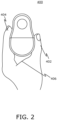
- the second portion of the main frame of the apparatus 400 is curved in shape, the curved area allows the apparatus 400 to be hold against a purlicue 406 between the thumb 402 and index finger 404, making it feel comfortable and safe to hold the apparatus in the position intended for use.
- the apparatus 400 may be used entirely by the index finger 404, purlicue 406 and thumb 402 of the user. It is also characteristics that the upper part (in FIG. 2 the region, which is near the fingertips) is laterally narrower than the lower part (in FIG. 2 the region, which is near the purlicue, i.e., the housing).
Landscapes
- Health & Medical Sciences (AREA)
- Life Sciences & Earth Sciences (AREA)
- Surgery (AREA)
- Physics & Mathematics (AREA)
- Engineering & Computer Science (AREA)
- Medical Informatics (AREA)
- Animal Behavior & Ethology (AREA)
- Veterinary Medicine (AREA)
- Public Health (AREA)
- General Health & Medical Sciences (AREA)
- Biomedical Technology (AREA)
- Heart & Thoracic Surgery (AREA)
- Biophysics (AREA)
- Molecular Biology (AREA)
- Pathology (AREA)
- Nuclear Medicine, Radiotherapy & Molecular Imaging (AREA)
- Optics & Photonics (AREA)
- Radiology & Medical Imaging (AREA)
- Otolaryngology (AREA)
- Acoustics & Sound (AREA)
- Audiology, Speech & Language Pathology (AREA)
- Multimedia (AREA)
- Endoscopes (AREA)
- Measurement Of The Respiration, Hearing Ability, Form, And Blood Characteristics Of Living Organisms (AREA)
Claims (11)
- Appareil (100, 400) pour un examen de l'oreille d'un sujet, l'appareil étant caractérisé en ce qu'il comprend,- une chambre avant amovible (102) ; et- un cadre principal (104) présentant une première partie (106) et une seconde partie (108), la première partie (106) étant adjacente à la seconde partie (108), la première partie (106) comprenant : une extrémité proximale (106A) conçue pour adapter un spéculum auriculaire qui est configuré pour entrer en contact au moins partiellement avec une oreille du sujet et une extrémité distale (106B) configurée pour recevoir au moins partiellement la chambre avant amovible (102) à l'intérieur de celle-ci et la seconde partie (108) comprenant un boîtier pour loger des composants électroniques, et un moyen de préhension (112) sur une surface externe du boîtier, dans lequel la chambre avant amovible (108) est configurée pour être couplée de manière amovible au cadre principal (104) pour permettre l'accès à un conduit auditif du sujet.
- Appareil (100, 400) selon la revendication 1, dans lequel la chambre avant amovible (102) est configurée pour accueillir ou être remplacée par au moins un outil.
- Appareil (100, 400) selon la revendication 2, dans lequel le au moins un outil comprend :- un dispositif de diagnostic visuel sélectionné parmi au moins un élément parmi : au moins une caméra, une caméra mobile, des sources de lumière, et/ou- un dispositif de diagnostic acoustique sélectionné parmi au moins un élément parmi : un détecteur de tympanométrie, réflectométrie acoustique, d'émissions otoacoustiques.
- Appareil (100, 400) selon la revendication 2 ou 3, dans lequel le au moins un outil est configuré pour être actionné lors de la réception d'au moins l'une parmi : une connexion mécanique et une connexion électrique à partir du cadre principal (104).
- Appareil (100, 400) selon l'une quelconque des revendications précédentes, dans lequel le moyen de préhension (112) est sélectionné parmi l'un quelconque parmi : une indentation, une fente, un polygone.
- Appareil (100, 400) selon l'une quelconque des revendications précédentes, dans lequel l'un quelconque parmi : la chambre avant amovible (102) ou le cadre principal (104) comprend un système de pressurisation et un capteur.
- Appareil (100, 400) selon l'une quelconque des revendications précédentes, dans lequel la chambre avant amovible (102) est scellée de manière étanche à l'air au cadre principal (104) à l'aide d'au moins un élément parmi : des aimants, un électroaimant, un raccord mécanique avec ou sans pneumatique ou hydraulique.
- Appareil (100, 400) selon l'une quelconque des revendications précédentes, dans lequel le cadre principal (104) comprend en outre une batterie, des composants électriques, un microphone ou une combinaison de ceux-ci.
- Appareil (100, 400) selon l'une quelconque des revendications précédentes, dans lequel la première partie (106) comprend l'extrémité proximale (106A), l'extrémité distale (106B) et une partie en entonnoir (106C) entre celles-ci qui sont formées d'un seul tenant avec le cadre principal (104) et configurées pour faire saillie vers l'extérieur à partir de la première partie (106), à l'opposé d'une surface de réception (114) de la première partie (106), qui est configurée pour recevoir une surface inférieure (113) de la chambre avant amovible (102).
- Appareil (100, 400) selon l'une quelconque des revendications précédentes, dans lequel lorsque la chambre avant amovible (102) est fixée au cadre principal (104), les surfaces supérieures de la chambre avant amovible (101) et du cadre principal (104) sont configurées pour s'aligner afin de former une surface inclinée lisse qui s'étend sur l'appareil.
- Appareil (100, 400) selon l'une quelconque des revendications précédentes, dans lequel des bords latéraux entourant l'appareil, consistant en un bord latéral avant de la chambre avant amovible (102) et une surface externe du boîtier avec le moyen de préhension (112), sont configurés pour s'aligner et former un bord latéral incurvé lisse qui s'étend sur la circonférence extérieure de l'appareil, autour de l'appareil.
Applications Claiming Priority (2)
| Application Number | Priority Date | Filing Date | Title |
|---|---|---|---|
| FI20225919A FI20225919A1 (en) | 2022-10-11 | 2022-10-11 | DEVICE AND SYSTEM FOR EXAMINING THE EAR |
| PCT/FI2023/050571 WO2024079386A1 (fr) | 2022-10-11 | 2023-10-05 | Appareil et système d'examen de l'oreille |
Publications (3)
| Publication Number | Publication Date |
|---|---|
| EP4429533A1 EP4429533A1 (fr) | 2024-09-18 |
| EP4429533B1 true EP4429533B1 (fr) | 2025-04-16 |
| EP4429533C0 EP4429533C0 (fr) | 2025-04-16 |
Family
ID=88412980
Family Applications (1)
| Application Number | Title | Priority Date | Filing Date |
|---|---|---|---|
| EP23790043.6A Active EP4429533B1 (fr) | 2022-10-11 | 2023-10-05 | Appareil et système d'examen de l'oreille |
Country Status (3)
| Country | Link |
|---|---|
| EP (1) | EP4429533B1 (fr) |
| FI (1) | FI20225919A1 (fr) |
| WO (1) | WO2024079386A1 (fr) |
Family Cites Families (2)
| Publication number | Priority date | Publication date | Assignee | Title |
|---|---|---|---|---|
| EP3998930B1 (fr) * | 2019-07-17 | 2025-09-10 | Tusker Medical, Inc. | Système permettant la visualisation pendant des actes médicaux |
| CN116829048A (zh) * | 2021-01-28 | 2023-09-29 | 强生消费者公司 | 夹式医疗设备与智能设备相机的对准 |
-
2022
- 2022-10-11 FI FI20225919A patent/FI20225919A1/en unknown
-
2023
- 2023-10-05 WO PCT/FI2023/050571 patent/WO2024079386A1/fr not_active Ceased
- 2023-10-05 EP EP23790043.6A patent/EP4429533B1/fr active Active
Also Published As
| Publication number | Publication date |
|---|---|
| WO2024079386A1 (fr) | 2024-04-18 |
| EP4429533A1 (fr) | 2024-09-18 |
| FI20225919A1 (en) | 2024-04-12 |
| EP4429533C0 (fr) | 2025-04-16 |
Similar Documents
| Publication | Publication Date | Title |
|---|---|---|
| US12357166B2 (en) | Otoscope providing low obstruction electronic display | |
| US11957503B2 (en) | Electronic stethoscope with accessories | |
| AU2003218069B2 (en) | Combination otoscope | |
| US7976474B2 (en) | Ear canal obstruction detecting acoustical stimulation ear probe | |
| US20100239126A1 (en) | Apparatus and method for measuring a distance to an eardrum | |
| CN105358034A (zh) | 确定受试者的耳部的状况的耳部检查装置和方法 | |
| JP2005519666A5 (fr) | ||
| JP4953367B2 (ja) | 聴診器付属品および聴診器システム | |
| CA3085355A1 (fr) | Otoscope ayant un affichage electronique a faible obstruction | |
| JPH07111987A (ja) | 中耳の動特性測定および観察装置 | |
| KR20170050031A (ko) | 만능 귀 검사기 | |
| Lilly et al. | Wideband acoustic immittance measurements of the middle ear: introduction and some historical antecedents | |
| EP4429533B1 (fr) | Appareil et système d'examen de l'oreille | |
| JP2007236812A (ja) | 内視鏡、及び内視鏡装置 | |
| CN114945309A (zh) | 光学设备 | |
| JP4897682B2 (ja) | 外科用器具の位置を測定するための装置 | |
| EP4709254A1 (fr) | Sonde auriculaire pour examen de l'oreille | |
| US20020080988A1 (en) | Earpiece for auditory testing | |
| TW201705898A (zh) | 可與手持式行動裝置結合的簡易式耳鏡 | |
| EP3821782A1 (fr) | Dispositif médical | |
| CN120837799A (zh) | 可调式多光谱小鼠气管插管定位器 | |
| Rees | Tympanometry as an Aid in the Diagnosis of Middle Ear Disease: A Description of a New and Important Procedure for the Pediatric Practitioner | |
| KR20040003938A (ko) | 전자식 청진기 |
Legal Events
| Date | Code | Title | Description |
|---|---|---|---|
| STAA | Information on the status of an ep patent application or granted ep patent |
Free format text: STATUS: UNKNOWN |
|
| STAA | Information on the status of an ep patent application or granted ep patent |
Free format text: STATUS: THE INTERNATIONAL PUBLICATION HAS BEEN MADE |
|
| PUAI | Public reference made under article 153(3) epc to a published international application that has entered the european phase |
Free format text: ORIGINAL CODE: 0009012 |
|
| STAA | Information on the status of an ep patent application or granted ep patent |
Free format text: STATUS: REQUEST FOR EXAMINATION WAS MADE |
|
| 17P | Request for examination filed |
Effective date: 20240613 |
|
| AK | Designated contracting states |
Kind code of ref document: A1 Designated state(s): AL AT BE BG CH CY CZ DE DK EE ES FI FR GB GR HR HU IE IS IT LI LT LU LV MC ME MK MT NL NO PL PT RO RS SE SI SK SM TR |
|
| GRAP | Despatch of communication of intention to grant a patent |
Free format text: ORIGINAL CODE: EPIDOSNIGR1 |
|
| STAA | Information on the status of an ep patent application or granted ep patent |
Free format text: STATUS: GRANT OF PATENT IS INTENDED |
|
| INTG | Intention to grant announced |
Effective date: 20241112 |
|
| GRAS | Grant fee paid |
Free format text: ORIGINAL CODE: EPIDOSNIGR3 |
|
| GRAA | (expected) grant |
Free format text: ORIGINAL CODE: 0009210 |
|
| STAA | Information on the status of an ep patent application or granted ep patent |
Free format text: STATUS: THE PATENT HAS BEEN GRANTED |
|
| AK | Designated contracting states |
Kind code of ref document: B1 Designated state(s): AL AT BE BG CH CY CZ DE DK EE ES FI FR GB GR HR HU IE IS IT LI LT LU LV MC ME MK MT NL NO PL PT RO RS SE SI SK SM TR |
|
| DAV | Request for validation of the european patent (deleted) | ||
| DAX | Request for extension of the european patent (deleted) | ||
| REG | Reference to a national code |
Ref country code: GB Ref legal event code: FG4D |
|
| REG | Reference to a national code |
Ref country code: CH Ref legal event code: EP |
|
| REG | Reference to a national code |
Ref country code: IE Ref legal event code: FG4D |
|
| REG | Reference to a national code |
Ref country code: DE Ref legal event code: R096 Ref document number: 602023002985 Country of ref document: DE |
|
| U01 | Request for unitary effect filed |
Effective date: 20250430 |
|
| U07 | Unitary effect registered |
Designated state(s): AT BE BG DE DK EE FI FR IT LT LU LV MT NL PT RO SE SI Effective date: 20250508 |
|
| PG25 | Lapsed in a contracting state [announced via postgrant information from national office to epo] |
Ref country code: ES Free format text: LAPSE BECAUSE OF FAILURE TO SUBMIT A TRANSLATION OF THE DESCRIPTION OR TO PAY THE FEE WITHIN THE PRESCRIBED TIME-LIMIT Effective date: 20250416 |
|
| PG25 | Lapsed in a contracting state [announced via postgrant information from national office to epo] |
Ref country code: NO Free format text: LAPSE BECAUSE OF FAILURE TO SUBMIT A TRANSLATION OF THE DESCRIPTION OR TO PAY THE FEE WITHIN THE PRESCRIBED TIME-LIMIT Effective date: 20250716 Ref country code: GR Free format text: LAPSE BECAUSE OF FAILURE TO SUBMIT A TRANSLATION OF THE DESCRIPTION OR TO PAY THE FEE WITHIN THE PRESCRIBED TIME-LIMIT Effective date: 20250717 |
|
| PG25 | Lapsed in a contracting state [announced via postgrant information from national office to epo] |
Ref country code: PL Free format text: LAPSE BECAUSE OF FAILURE TO SUBMIT A TRANSLATION OF THE DESCRIPTION OR TO PAY THE FEE WITHIN THE PRESCRIBED TIME-LIMIT Effective date: 20250416 |
|
| PG25 | Lapsed in a contracting state [announced via postgrant information from national office to epo] |
Ref country code: HR Free format text: LAPSE BECAUSE OF FAILURE TO SUBMIT A TRANSLATION OF THE DESCRIPTION OR TO PAY THE FEE WITHIN THE PRESCRIBED TIME-LIMIT Effective date: 20250416 |
|
| PG25 | Lapsed in a contracting state [announced via postgrant information from national office to epo] |
Ref country code: RS Free format text: LAPSE BECAUSE OF FAILURE TO SUBMIT A TRANSLATION OF THE DESCRIPTION OR TO PAY THE FEE WITHIN THE PRESCRIBED TIME-LIMIT Effective date: 20250716 |
|
| PG25 | Lapsed in a contracting state [announced via postgrant information from national office to epo] |
Ref country code: IS Free format text: LAPSE BECAUSE OF FAILURE TO SUBMIT A TRANSLATION OF THE DESCRIPTION OR TO PAY THE FEE WITHIN THE PRESCRIBED TIME-LIMIT Effective date: 20250816 |
|
| U20 | Renewal fee for the european patent with unitary effect paid |
Year of fee payment: 3 Effective date: 20251006 |
|
| PG25 | Lapsed in a contracting state [announced via postgrant information from national office to epo] |
Ref country code: SM Free format text: LAPSE BECAUSE OF FAILURE TO SUBMIT A TRANSLATION OF THE DESCRIPTION OR TO PAY THE FEE WITHIN THE PRESCRIBED TIME-LIMIT Effective date: 20250416 |
|
| PG25 | Lapsed in a contracting state [announced via postgrant information from national office to epo] |
Ref country code: CZ Free format text: LAPSE BECAUSE OF FAILURE TO SUBMIT A TRANSLATION OF THE DESCRIPTION OR TO PAY THE FEE WITHIN THE PRESCRIBED TIME-LIMIT Effective date: 20250416 |
|
| PG25 | Lapsed in a contracting state [announced via postgrant information from national office to epo] |
Ref country code: SK Free format text: LAPSE BECAUSE OF FAILURE TO SUBMIT A TRANSLATION OF THE DESCRIPTION OR TO PAY THE FEE WITHIN THE PRESCRIBED TIME-LIMIT Effective date: 20250416 |
|
| PLBE | No opposition filed within time limit |
Free format text: ORIGINAL CODE: 0009261 |
|
| STAA | Information on the status of an ep patent application or granted ep patent |
Free format text: STATUS: NO OPPOSITION FILED WITHIN TIME LIMIT |
|
| REG | Reference to a national code |
Ref country code: CH Ref legal event code: L10 Free format text: ST27 STATUS EVENT CODE: U-0-0-L10-L00 (AS PROVIDED BY THE NATIONAL OFFICE) Effective date: 20260225 |
|
| 26N | No opposition filed |
Effective date: 20260119 |