EP4430992B1 - Gruppenkopf mit wirbeldusche - Google Patents
Gruppenkopf mit wirbeldusche Download PDFInfo
- Publication number
- EP4430992B1 EP4430992B1 EP23173554.9A EP23173554A EP4430992B1 EP 4430992 B1 EP4430992 B1 EP 4430992B1 EP 23173554 A EP23173554 A EP 23173554A EP 4430992 B1 EP4430992 B1 EP 4430992B1
- Authority
- EP
- European Patent Office
- Prior art keywords
- wall
- group head
- bottom wall
- central axis
- water
- Prior art date
- Legal status (The legal status is an assumption and is not a legal conclusion. Google has not performed a legal analysis and makes no representation as to the accuracy of the status listed.)
- Active
Links
Images




Classifications
-
- A—HUMAN NECESSITIES
- A47—FURNITURE; DOMESTIC ARTICLES OR APPLIANCES; COFFEE MILLS; SPICE MILLS; SUCTION CLEANERS IN GENERAL
- A47J—KITCHEN EQUIPMENT; COFFEE MILLS; SPICE MILLS; APPARATUS FOR MAKING BEVERAGES
- A47J31/00—Apparatus for making beverages
- A47J31/44—Parts or details or accessories of beverage-making apparatus
- A47J31/4403—Constructional details
- A47J31/4475—Hot water outlets for drip coffee makers
- A47J31/4478—Spreader plates
Definitions
- the invention relates to a group head shower, and more particularly to a group head vortex shower.
- a conventional coffee machine 9 includes a water supply unit 91 that provides water for extracting coffee, and an extraction unit 92 that is removably mounted on the water supply unit 91 and that is adapted to hold ground coffee.
- the water supply unit 91 is able to supply a sufficient amount of water with a suitable temperature and pressure for extracting coffee.
- the water supply unit 91 requires complex machinery in order to control the temperature and pressure parameters of the water so that the supplied water is optimal for coffee extraction.
- the conventional coffee machine 9 therefore requires a lot more space to house the more complex machinery of the water supply unit 91. Therefore the conventional coffee machine 9 has the disadvantage of taking up too much space, and being less convenient to use.
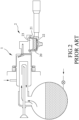
- a second conventional coffee machine includes a water inlet unit 1 that supplies water, and an extraction unit 2 that is connected to the water inlet unit 1 to be in fluid communication with the water inlet unit 1.
- the extraction unit 2 includes a body 21 defining an inner space 20, a portafilter basket 22 that is disposed in the inner space 20 and that is adapted to receive ground coffee, and a water distribution module 23 that is in liquid communication with the water inlet unit 1.
- the water diffusion module 23 is used to adjust the relevant parameters of the water according to required specifications.
- the water distribution module 23 includes a disc body 231 that defines an inlet hole 230, a group head shower screen 232 that is attached to the disc body 231 and that has a central through hole 39, and a group head diffusion screw 233 that has a diffusion hole 235.
- the group head diffusion screw 233 is screwed into the inlet hole 230 of the disc body 231 through the group head shower screen 232 and secures the group head shower screen 232 to the disc body 231.
- the water supplied by the water inlet unit 1 is able to diffuse from the diffusion hole 235 of the group head diffusion screw 233 through the group head shower screen 232 and reach the portafilter basket 22 evenly.
- US 2011/094393 A1 discloses an example of a spray head for a coffee machine.
- the water diffusion distribution 23 can diffuse water via the group head shower screen 232 to evenly percolate downward into the portafilter basket 22, the group head shower screen 232 causes the water to flow through a plurality of vertically open pores (not shown), so that the water can only diffuse vertically downward and cannot agitate the ground coffee in the portafilter basket 22 transversely to achieve better extraction of the ground coffee.
- the coffee extraction process is pressurized, which means residue water from the extraction process in the portafilter basket 22 will be sucked back up the second conventional coffee machine through the group head shower screen 232 along with some of the ground coffee in the portafilter basket 22, when the pressure is released after the extraction.
- an object of the disclosure is to provide a group head vortex shower that can alleviate at least one of the drawbacks of the prior art.
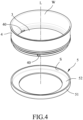
- a first embodiment of the group head vortex shower includes a bottom wall 3, a surrounding wall 4, and a reflection wall 5.
- the surrounding wall 4 extends upwardly from an outer periphery of the bottom wall 3, surrounds a central axis (L), cooperates with the bottom wall 3 to define a water inlet space (W), and has a plurality of outer outlets 40 that extends therethrough and that are in fluid communication with the water inlet space (W).
- the reflection wall 5 is sleeved around the surrounding wall 4, and has at least one curved inner surface (S) that face the outer outlets 40 and that surrounds the central axis (L).
- Each of the outer outlets 40 is disposed for outputting a water jet from the water inlet space (W) in a water outlet direction (D1...to...DN) towards the at least one curved inner surface (S) of the reflection wall 5 (see Figure 5 ).
- An imaginary extension line (L1...to...LN) extending in the water outlet direction (D1...to...DN) of each of the outer outlets 40 and the central axis (L) are skew lines. More specifically, the reflection wall 5 may be manufactured separately, and may be welded, fused or glued to the bottom wall 3.
- the reflection wall 5 includes a surrounding portion 51 that surrounds the outer outlets 40, and an abutting portion 52 that is connected transversely to a lower end of the surrounding portion 51 and that abuts against the bottom wall 3 so that the reflection wall 5 is more securely affixed to the bottom wall 3.
- the at least one curved inner surface (S) is the inner surface of the surrounding portion 51 that faces the outer outlets 40 and that surrounds the central axis (L).
- the first embodiment has the reflection wall 5 having the at least one curved inner surface (S) that faces the outer outlets 40, while, in the first embodiment, it is the portafilter basket 7 of the coffee machine 8 that faces the outer outlets 40.
- the outer outlets 40 output water jets that interact with the curved inner surface (S) of the reflection wall 5 to create an agitating force that whirls around the central axis (L), thereby creating a vortex that agitates the ground coffee.
- Figure 6 shows a variation of the first embodiment, in the first embodiment the carrying surface 31 of the bottom wall 3 is flat and perpendicular to the central axis (L); however, in the variation of the first embodiment the carrying surface 31 of the bottom wall 3 is conical and extends towards the water inlet space (W). This facilitates water flow and prevents residue water from remaining in the water inlet space (W).
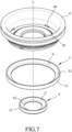
- Figures 7 and 8 show a second embodiment of the group head vortex shower according to the present disclosure.
- the second embodiment is similar to the first embodiment; however, the second embodiment is different in that the bottom wall 3 further has a bottom ring surface 33 that surrounds the central axis (L) and that face opposite to the central axis (L), and a plurality of spout holes 30 that extend through the bottom ring surface 33 and that is in fluid communication with the water inlet space (W).
- the third embodiment further includes a cooperating wall 6 that is connected to the bottom wall 3. More specifically, the bottom wall 3 further has a positioning groove 39 that is recessed from a bottom surface of the bottom wall 3 and that is for mounting the cooperating wall 6.
- the cooperating wall 6 has at least one arcuate surface (C) that faces the spout holes 30 and that surrounds the central axis (L).
- Each of the spout holes 30 is disposed for outputting a water jet from the water inlet space (W) in a water output direction (F1...to...FN) toward the at least one arcuate surface (C) of the cooperating wall 6.
- An imaginary extension line (P1...to...PN) extending in the water output direction (F1...to...FN) of each of the spout holes 30 and the central axis (L) are skew lines.
- the cooperating wall 6 includes an annular portion 61 that engages the positioning groove 39 and that has the arcuate surface (C), and an abutment portion 62 that is connected transversely to a lower end of the annular portion 61 and that abuts against the bottom wall 3.
- the at least one arcuate surface (C) is the inner surface of the annular portion 61 that faces the spout holes 30 and that surrounds the central axis (L).
- the cooperating wall 6 may be mounted via fusing, welding or gluing to the bottom wall 3 so that the annular portion 61 of the cooperating wall 6 is mounted in the positioning groove 39 of the bottom wall 3.
- the second embodiments is able to output an additional set of water jets closer to the central axis (L).
- the water jets contact the arcuate surface (C) of the cooperating wall 6 and from an additional vortex closer to the central axis (L).
- This helps to agitate the ground coffee even more vigorously then the second embodiment as there are now two vortices, one formed from water jets outputted from the outer outlets 40 and created upon contact with the curved inner surface (S) that is more distal to the central axis (L), and another one formed from water jets issued from the spout holes 30 and created upon contacting the arcuate surface (C) that is more proximate to the central axis (L).
- This will not only agitate the ground coffee more vigorously, but also, make the agitation more uniform.
- the outer outlets 40 are able to output water jets that interact with the curved inner surface (S) of the reflection wall 5, and the spout holes 30 are able to output water jets that interact with the arcuate surface (C), thereby creating a vortices to uniformly agitate ground coffee in the portafilter basket 7 and optimize coffee extraction.
- the outer outlets 40 and the spout holes 30 of the group head vortex shower are larger and easier to clean when compared to conventional group head screen showers that have small pores. This ensures the extracted coffee will not be affected by residue coffee grounds and affect user satisfaction.
Landscapes
- Engineering & Computer Science (AREA)
- Food Science & Technology (AREA)
- Apparatus For Making Beverages (AREA)
Claims (8)
- Eine Gruppenhauptwirbeldusche, die für die Verwendung in einer Kaffeemaschine (8) angepasst ist und eine Bodenwand (3) umfasst, dadurch gekennzeichnet, dass die Gruppenhauptwirbeldusche ferner umfasst:• eine umgebende Wand (4), die sich von einem äußeren Rand der Bodenwand (3) nach oben erstreckt, eine zentrale Achse (L) umgibt, mit der Bodenwand (3) zusammenarbeitet, um einen Wassereinlassraum (W) zu definieren, und eine Vielzahl von äußeren Auslässen (40) aufweist, die sich durch die Wand erstrecken und in Flüssigkeitskommunikation mit dem Wassereinlassraum (W) stehen; und• eine Reflexionswand (5), die um die umgebende Wand (4) herum angeordnet ist und mindestens eine gekrümmte Innenfläche (S) aufweist, die den äußeren Auslässen (40) zugewandt ist und die zentrale Achse (L) umgibt;• wobei jeder der äußeren Auslässe (40) so angeordnet ist, dass er einen Wasserstrahl aus dem Wassereinlassraum (W) in eine Wasserauslassrichtung (D1...bis...DN) zu mindestens einer gekrümmten Innenfläche (S) der Reflexionswand (5) ausgibt; und• wobei eine imaginäre Verlängerungslinie (L1...bis...LN), die sich in der Wasserauslassrichtung (D1...bis...DN) jedes der äußeren Auslässe (40) erstreckt, und die zentrale Achse (L) schiefe Linien sind.
- Die Gruppenhauptwirbeldusche nach Anspruch 1, wobei die Bodenwand (3) eine Trägerfläche (31) aufweist, die dem Wassereinlassraum (W) zugewandt ist, und eine Führungsfläche (32), die konisch ist, der Trägerfläche (31) gegenüberliegt und sich in eine Richtung vom Wassereinlassraum (W) weg erstreckt.
- Die Gruppenhauptwirbeldusche nach Anspruch 2, wobei die Trägerfläche (31) der Bodenwand (3) flach und senkrecht zur zentralen Achse (L) ist.
- Die Gruppenhauptwirbeldusche nach Anspruch 2, wobei die Trägerfläche (31) der Bodenwand (3) konisch ist und sich zum Wassereinlassraum (W) hin erstreckt.
- Die Gruppenhauptwirbeldusche nach Anspruch 1, wobei die Bodenwand (3) eine Bodenringfläche (33) aufweist, die die zentrale Achse (L) umgibt und der zentralen Achse (L) gegenüberliegt, und eine Vielzahl von Auslauföffnungen (30), die sich durch die Bodenringfläche (33) erstrecken und in Flüssigkeitskommunikation mit dem Wassereinlassraum (W) stehen; die Gruppenhauptwirbeldusche ferner eine Kooperationswand (6) umfasst, die mit der Bodenwand (3) verbunden ist und mindestens eine bogenförmige Fläche (C) aufweist, die den Auslauföffnungen (30) zugewandt ist und die zentrale Achse (L) umgibt; jede der Auslauföffnungen (30) so angeordnet ist, dass sie einen Wasserstrahl aus dem Wassereinlassraum (W) in eine Wasserauslassrichtung (F1...bis...FN) zu mindestens einer bogenförmigen Fläche (C) der Kooperationswand (6) ausgibt; und eine imaginäre Verlängerungslinie (P1...bis...PN), die sich in der Wasserauslassrichtung (F1...bis...FN) jeder der Auslauföffnungen (30) erstreckt, und die zentrale Achse (L) schiefe Linien sind.
- Die Gruppenhauptwirbeldusche nach Anspruch 5, wobei die Bodenwand (3) ferner eine Positionierungsnut (39) aufweist, die von einer Bodenfläche der Bodenwand (3) zurückgesetzt ist und zur Montage der Kooperationswand (6) dient.
- Die Gruppenhauptwirbeldusche nach Anspruch 6, wobei die Kooperationswand (6) einen ringförmigen Abschnitt (61) umfasst, der die Positionierungsnut (39) einrastet und die bogenförmige Fläche (C) aufweist, und einen Anschlagabschnitt (62), der quer zu einem unteren Ende des ringförmigen Abschnitts (61) verbunden ist und gegen die Bodenwand (3) anstößt.
- Die Gruppenhauptwirbeldusche nach den Ansprüchen 1 bis 7, wobei die Reflexionswand (5) einen umgebenden Abschnitt (51) umfasst, der die äußeren Auslässe (40) umgibt und die mindestens eine gekrümmte Innenfläche (S) aufweist, und einen Anschlagabschnitt (51), der quer zu einem unteren Ende des umgebenden Abschnitts (51) verbunden ist und gegen die Bodenwand (3) anstößt.
Applications Claiming Priority (1)
| Application Number | Priority Date | Filing Date | Title |
|---|---|---|---|
| TW112109497A TWI819977B (zh) | 2023-03-15 | 2023-03-15 | 咖啡機的漩渦式分水盤 |
Publications (2)
| Publication Number | Publication Date |
|---|---|
| EP4430992A1 EP4430992A1 (de) | 2024-09-18 |
| EP4430992B1 true EP4430992B1 (de) | 2025-04-30 |
Family
ID=86386926
Family Applications (1)
| Application Number | Title | Priority Date | Filing Date |
|---|---|---|---|
| EP23173554.9A Active EP4430992B1 (de) | 2023-03-15 | 2023-05-16 | Gruppenkopf mit wirbeldusche |
Country Status (3)
| Country | Link |
|---|---|
| US (1) | US12453437B2 (de) |
| EP (1) | EP4430992B1 (de) |
| TW (1) | TWI819977B (de) |
Family Cites Families (15)
| Publication number | Priority date | Publication date | Assignee | Title |
|---|---|---|---|---|
| US1803356A (en) * | 1929-07-20 | 1931-05-05 | Isaac D Richheimer | Percolator |
| US3935805A (en) * | 1973-10-03 | 1976-02-03 | Dart Industries Inc. | Spreader closure |
| FR2634365A1 (fr) * | 1988-07-20 | 1990-01-26 | Seb Sa | Couvercle pour bac a mouture et verseuse de cafetiere electrique |
| FR2702943B1 (fr) * | 1993-03-24 | 1995-05-19 | Seb Sa | Machïne à boisson chaude pourvue d'un dispositif de variation du goût de la boisson. |
| US6755119B1 (en) * | 2002-06-05 | 2004-06-29 | Wilbur Curtis Company, Inc. | Coffee spray head |
| EP1502526B8 (de) * | 2003-07-28 | 2007-09-12 | Merz Michaela | Kaffeefilteraufsatz |
| US7429005B2 (en) * | 2004-02-02 | 2008-09-30 | Orbit Irrigation Products, Inc. | Adjustable spray pattern sprinkler |
| JPWO2006129373A1 (ja) * | 2005-06-03 | 2008-12-25 | 株式会社デバイスタイルホールディングス | 飲料抽出装置用の給湯ノズルおよび飲料抽出装置 |
| US9084511B2 (en) * | 2009-10-22 | 2015-07-21 | Bunn-O-Matic Corporation | Flexible spray head |
| JP6559683B2 (ja) * | 2013-12-31 | 2019-08-14 | コーニンクレッカ フィリップス エヌ ヴェKoninklijke Philips N.V. | 飲料マシン |
| EP3469962B1 (de) * | 2017-10-11 | 2020-02-26 | Simonelli Group S.P.A. | Schnell entkoppelndes sieb für espressokaffeemaschinen |
| TWI712386B (zh) * | 2019-12-31 | 2020-12-11 | 亞弘電科技股份有限公司 | 仿手沖咖啡機及導流器 |
| NL2025661B1 (en) * | 2020-05-25 | 2021-12-13 | Spinn Holding B V | Improved centrifugal coffee brewer |
| CN214964594U (zh) * | 2021-02-01 | 2021-12-03 | 好璃奥(上海)商贸有限公司 | 一种分水器以及应用该分水器的分水装置 |
| TWM642140U (zh) * | 2023-03-15 | 2023-06-01 | 一丞冷凍工業股份有限公司 | 咖啡機的漩渦式分水盤 |
-
2023
- 2023-03-15 TW TW112109497A patent/TWI819977B/zh active
- 2023-05-16 EP EP23173554.9A patent/EP4430992B1/de active Active
- 2023-06-13 US US18/209,122 patent/US12453437B2/en active Active
Also Published As
| Publication number | Publication date |
|---|---|
| TWI819977B (zh) | 2023-10-21 |
| TW202437976A (zh) | 2024-10-01 |
| US12453437B2 (en) | 2025-10-28 |
| US20240306837A1 (en) | 2024-09-19 |
| EP4430992A1 (de) | 2024-09-18 |
Similar Documents
| Publication | Publication Date | Title |
|---|---|---|
| US7150219B2 (en) | Filter cup for coffee machine and coffee-making process | |
| US5862740A (en) | Device for frothing and heating liquids, such as milk and the like, provided with longitudinal channels for suction of the liquid-frothing air | |
| CN103169373B (zh) | 具有用于卡布奇诺的奶沫产生装置的咖啡机/浓缩咖啡机 | |
| JP7012482B2 (ja) | 微細気泡水生成器 | |
| US7958815B2 (en) | Beverage device for making a beverage with a foam layer on top | |
| US6250208B1 (en) | Tea brewing apparatus | |
| CN102038432B (zh) | 柔性喷头 | |
| KR100528819B1 (ko) | 시럽음료 공급 노즐장치 | |
| EP1371311B1 (de) | Vorrichtung zur Zubereitung einer Getränkeportion mit einer feinblasigen Schaumschicht | |
| EP0344859B1 (de) | Vorrichtung zum Schäumen und Erhitzen von Milch für Getränke | |
| JP5306452B2 (ja) | 飲料分配排出口 | |
| US20050268790A1 (en) | Apparatus for the production of espresso coffee and the like | |
| MX2007015712A (es) | Sistema portafiltro. | |
| CN105263374A (zh) | 具有内部上升部、凹下部和开孔的喷头组件 | |
| EP1092377A1 (de) | Gerät zum Zubereiten einer Kaffeeinfusion mit einer dünnen Schaumschicht | |
| US12453437B2 (en) | Group head vortex shower | |
| CN211862509U (zh) | 烹饪器具 | |
| US8549990B2 (en) | Coffeemaker comprising a foam-making device | |
| KR20100104225A (ko) | 커피메이커 | |
| CN100542463C (zh) | 饮料制造设备 | |
| CN111503316B (zh) | 分配装置和分配装置的组装方法 | |
| EP3155937A1 (de) | Vorrichtung zur getränkeausgabe mit doppeltem auslauf, und kaffeemaschine, die eine solche vorrichtung umfasst | |
| CN108348091A (zh) | 流量可调节的冲泡篮 | |
| CN115067777A (zh) | 一种不用手洗食品加工机 | |
| JPS641132B2 (de) |
Legal Events
| Date | Code | Title | Description |
|---|---|---|---|
| PUAI | Public reference made under article 153(3) epc to a published international application that has entered the european phase |
Free format text: ORIGINAL CODE: 0009012 |
|
| STAA | Information on the status of an ep patent application or granted ep patent |
Free format text: STATUS: REQUEST FOR EXAMINATION WAS MADE |
|
| 17P | Request for examination filed |
Effective date: 20240202 |
|
| AK | Designated contracting states |
Kind code of ref document: A1 Designated state(s): AL AT BE BG CH CY CZ DE DK EE ES FI FR GB GR HR HU IE IS IT LI LT LU LV MC ME MK MT NL NO PL PT RO RS SE SI SK SM TR |
|
| GRAP | Despatch of communication of intention to grant a patent |
Free format text: ORIGINAL CODE: EPIDOSNIGR1 |
|
| STAA | Information on the status of an ep patent application or granted ep patent |
Free format text: STATUS: GRANT OF PATENT IS INTENDED |
|
| INTG | Intention to grant announced |
Effective date: 20241205 |
|
| GRAS | Grant fee paid |
Free format text: ORIGINAL CODE: EPIDOSNIGR3 |
|
| GRAA | (expected) grant |
Free format text: ORIGINAL CODE: 0009210 |
|
| STAA | Information on the status of an ep patent application or granted ep patent |
Free format text: STATUS: THE PATENT HAS BEEN GRANTED |
|
| AK | Designated contracting states |
Kind code of ref document: B1 Designated state(s): AL AT BE BG CH CY CZ DE DK EE ES FI FR GB GR HR HU IE IS IT LI LT LU LV MC ME MK MT NL NO PL PT RO RS SE SI SK SM TR |
|
| REG | Reference to a national code |
Ref country code: CH Ref legal event code: EP Ref country code: GB Ref legal event code: FG4D |
|
| REG | Reference to a national code |
Ref country code: IE Ref legal event code: FG4D |
|
| REG | Reference to a national code |
Ref country code: DE Ref legal event code: R096 Ref document number: 602023003137 Country of ref document: DE |
|
| PGFP | Annual fee paid to national office [announced via postgrant information from national office to epo] |
Ref country code: AT Payment date: 20250721 Year of fee payment: 3 |
|
| REG | Reference to a national code |
Ref country code: NL Ref legal event code: MP Effective date: 20250430 |
|
| REG | Reference to a national code |
Ref country code: AT Ref legal event code: MK05 Ref document number: 1789215 Country of ref document: AT Kind code of ref document: T Effective date: 20250430 |
|
| PG25 | Lapsed in a contracting state [announced via postgrant information from national office to epo] |
Ref country code: FI Free format text: LAPSE BECAUSE OF FAILURE TO SUBMIT A TRANSLATION OF THE DESCRIPTION OR TO PAY THE FEE WITHIN THE PRESCRIBED TIME-LIMIT Effective date: 20250430 Ref country code: PT Free format text: LAPSE BECAUSE OF FAILURE TO SUBMIT A TRANSLATION OF THE DESCRIPTION OR TO PAY THE FEE WITHIN THE PRESCRIBED TIME-LIMIT Effective date: 20250901 Ref country code: ES Free format text: LAPSE BECAUSE OF FAILURE TO SUBMIT A TRANSLATION OF THE DESCRIPTION OR TO PAY THE FEE WITHIN THE PRESCRIBED TIME-LIMIT Effective date: 20250430 |
|
| REG | Reference to a national code |
Ref country code: LT Ref legal event code: MG9D |
|
| PG25 | Lapsed in a contracting state [announced via postgrant information from national office to epo] |
Ref country code: NO Free format text: LAPSE BECAUSE OF FAILURE TO SUBMIT A TRANSLATION OF THE DESCRIPTION OR TO PAY THE FEE WITHIN THE PRESCRIBED TIME-LIMIT Effective date: 20250730 Ref country code: GR Free format text: LAPSE BECAUSE OF FAILURE TO SUBMIT A TRANSLATION OF THE DESCRIPTION OR TO PAY THE FEE WITHIN THE PRESCRIBED TIME-LIMIT Effective date: 20250731 |
|
| PG25 | Lapsed in a contracting state [announced via postgrant information from national office to epo] |
Ref country code: NL Free format text: LAPSE BECAUSE OF FAILURE TO SUBMIT A TRANSLATION OF THE DESCRIPTION OR TO PAY THE FEE WITHIN THE PRESCRIBED TIME-LIMIT Effective date: 20250430 Ref country code: PL Free format text: LAPSE BECAUSE OF FAILURE TO SUBMIT A TRANSLATION OF THE DESCRIPTION OR TO PAY THE FEE WITHIN THE PRESCRIBED TIME-LIMIT Effective date: 20250430 |
|
| PGFP | Annual fee paid to national office [announced via postgrant information from national office to epo] |
Ref country code: IT Payment date: 20250531 Year of fee payment: 3 |
|
| PG25 | Lapsed in a contracting state [announced via postgrant information from national office to epo] |
Ref country code: BG Free format text: LAPSE BECAUSE OF FAILURE TO SUBMIT A TRANSLATION OF THE DESCRIPTION OR TO PAY THE FEE WITHIN THE PRESCRIBED TIME-LIMIT Effective date: 20250430 |
|
| PG25 | Lapsed in a contracting state [announced via postgrant information from national office to epo] |
Ref country code: HR Free format text: LAPSE BECAUSE OF FAILURE TO SUBMIT A TRANSLATION OF THE DESCRIPTION OR TO PAY THE FEE WITHIN THE PRESCRIBED TIME-LIMIT Effective date: 20250430 |
|
| PG25 | Lapsed in a contracting state [announced via postgrant information from national office to epo] |
Ref country code: AT Free format text: LAPSE BECAUSE OF FAILURE TO SUBMIT A TRANSLATION OF THE DESCRIPTION OR TO PAY THE FEE WITHIN THE PRESCRIBED TIME-LIMIT Effective date: 20250430 |
|
| PG25 | Lapsed in a contracting state [announced via postgrant information from national office to epo] |
Ref country code: RS Free format text: LAPSE BECAUSE OF FAILURE TO SUBMIT A TRANSLATION OF THE DESCRIPTION OR TO PAY THE FEE WITHIN THE PRESCRIBED TIME-LIMIT Effective date: 20250731 |
|
| PG25 | Lapsed in a contracting state [announced via postgrant information from national office to epo] |
Ref country code: IS Free format text: LAPSE BECAUSE OF FAILURE TO SUBMIT A TRANSLATION OF THE DESCRIPTION OR TO PAY THE FEE WITHIN THE PRESCRIBED TIME-LIMIT Effective date: 20250830 |
|
| PG25 | Lapsed in a contracting state [announced via postgrant information from national office to epo] |
Ref country code: LV Free format text: LAPSE BECAUSE OF FAILURE TO SUBMIT A TRANSLATION OF THE DESCRIPTION OR TO PAY THE FEE WITHIN THE PRESCRIBED TIME-LIMIT Effective date: 20250430 |
|
| REG | Reference to a national code |
Ref country code: DE Ref legal event code: R119 Ref document number: 602023003137 Country of ref document: DE |
|
| PG25 | Lapsed in a contracting state [announced via postgrant information from national office to epo] |
Ref country code: SM Free format text: LAPSE BECAUSE OF FAILURE TO SUBMIT A TRANSLATION OF THE DESCRIPTION OR TO PAY THE FEE WITHIN THE PRESCRIBED TIME-LIMIT Effective date: 20250430 Ref country code: DK Free format text: LAPSE BECAUSE OF FAILURE TO SUBMIT A TRANSLATION OF THE DESCRIPTION OR TO PAY THE FEE WITHIN THE PRESCRIBED TIME-LIMIT Effective date: 20250430 |
|
| PG25 | Lapsed in a contracting state [announced via postgrant information from national office to epo] |
Ref country code: LU Free format text: LAPSE BECAUSE OF NON-PAYMENT OF DUE FEES Effective date: 20250516 |
|
| PG25 | Lapsed in a contracting state [announced via postgrant information from national office to epo] |
Ref country code: CZ Free format text: LAPSE BECAUSE OF FAILURE TO SUBMIT A TRANSLATION OF THE DESCRIPTION OR TO PAY THE FEE WITHIN THE PRESCRIBED TIME-LIMIT Effective date: 20250430 |
|
| PG25 | Lapsed in a contracting state [announced via postgrant information from national office to epo] |
Ref country code: EE Free format text: LAPSE BECAUSE OF FAILURE TO SUBMIT A TRANSLATION OF THE DESCRIPTION OR TO PAY THE FEE WITHIN THE PRESCRIBED TIME-LIMIT Effective date: 20250430 |
|
| PG25 | Lapsed in a contracting state [announced via postgrant information from national office to epo] |
Ref country code: SK Free format text: LAPSE BECAUSE OF FAILURE TO SUBMIT A TRANSLATION OF THE DESCRIPTION OR TO PAY THE FEE WITHIN THE PRESCRIBED TIME-LIMIT Effective date: 20250430 |
|
| REG | Reference to a national code |
Ref country code: BE Ref legal event code: MM Effective date: 20250531 |
|
| PG25 | Lapsed in a contracting state [announced via postgrant information from national office to epo] |
Ref country code: MC Free format text: LAPSE BECAUSE OF FAILURE TO SUBMIT A TRANSLATION OF THE DESCRIPTION OR TO PAY THE FEE WITHIN THE PRESCRIBED TIME-LIMIT Effective date: 20250430 |
|
| PLBE | No opposition filed within time limit |
Free format text: ORIGINAL CODE: 0009261 |
|
| STAA | Information on the status of an ep patent application or granted ep patent |
Free format text: STATUS: NO OPPOSITION FILED WITHIN TIME LIMIT |
|
| REG | Reference to a national code |
Ref country code: CH Ref legal event code: L10 Free format text: ST27 STATUS EVENT CODE: U-0-0-L10-L00 (AS PROVIDED BY THE NATIONAL OFFICE) Effective date: 20260311 |
|
| PG25 | Lapsed in a contracting state [announced via postgrant information from national office to epo] |
Ref country code: RO Free format text: LAPSE BECAUSE OF FAILURE TO SUBMIT A TRANSLATION OF THE DESCRIPTION OR TO PAY THE FEE WITHIN THE PRESCRIBED TIME-LIMIT Effective date: 20250430 |
|
| 26N | No opposition filed |
Effective date: 20260202 |
|
| PG25 | Lapsed in a contracting state [announced via postgrant information from national office to epo] |
Ref country code: IE Free format text: LAPSE BECAUSE OF NON-PAYMENT OF DUE FEES Effective date: 20250516 Ref country code: DE Free format text: LAPSE BECAUSE OF NON-PAYMENT OF DUE FEES Effective date: 20251202 |
|
| PG25 | Lapsed in a contracting state [announced via postgrant information from national office to epo] |
Ref country code: BE Free format text: LAPSE BECAUSE OF NON-PAYMENT OF DUE FEES Effective date: 20250531 |
|
| PG25 | Lapsed in a contracting state [announced via postgrant information from national office to epo] |
Ref country code: FR Free format text: LAPSE BECAUSE OF NON-PAYMENT OF DUE FEES Effective date: 20250630 |
|
| P01 | Opt-out of the competence of the unified patent court (upc) registered |
Free format text: CASE NUMBER: UPC_APP_0011755_4430992/2026 Effective date: 20260401 |