EP4431032A1 - Ensemble électrode à ondes de choc, appareil de cathéter à ballonnet et dispositif médical - Google Patents
Ensemble électrode à ondes de choc, appareil de cathéter à ballonnet et dispositif médical Download PDFInfo
- Publication number
- EP4431032A1 EP4431032A1 EP22891879.3A EP22891879A EP4431032A1 EP 4431032 A1 EP4431032 A1 EP 4431032A1 EP 22891879 A EP22891879 A EP 22891879A EP 4431032 A1 EP4431032 A1 EP 4431032A1
- Authority
- EP
- European Patent Office
- Prior art keywords
- shock wave
- hole
- electrode
- electrode assembly
- wave electrode
- Prior art date
- Legal status (The legal status is an assumption and is not a legal conclusion. Google has not performed a legal analysis and makes no representation as to the accuracy of the status listed.)
- Pending
Links
Images




Classifications
-
- A—HUMAN NECESSITIES
- A61—MEDICAL OR VETERINARY SCIENCE; HYGIENE
- A61M—DEVICES FOR INTRODUCING MEDIA INTO, OR ONTO, THE BODY; DEVICES FOR TRANSDUCING BODY MEDIA OR FOR TAKING MEDIA FROM THE BODY; DEVICES FOR PRODUCING OR ENDING SLEEP OR STUPOR
- A61M25/00—Catheters; Hollow probes
- A61M25/10—Balloon catheters
- A61M25/104—Balloon catheters used for angioplasty
-
- A—HUMAN NECESSITIES
- A61—MEDICAL OR VETERINARY SCIENCE; HYGIENE
- A61B—DIAGNOSIS; SURGERY; IDENTIFICATION
- A61B17/00—Surgical instruments, devices or methods
- A61B17/22—Implements for squeezing-off ulcers or the like on inner organs of the body; Implements for scraping-out cavities of body organs, e.g. bones; for invasive removal or destruction of calculus using mechanical vibrations; for removing obstructions in blood vessels, not otherwise provided for
- A61B17/22004—Implements for squeezing-off ulcers or the like on inner organs of the body; Implements for scraping-out cavities of body organs, e.g. bones; for invasive removal or destruction of calculus using mechanical vibrations; for removing obstructions in blood vessels, not otherwise provided for using mechanical vibrations, e.g. ultrasonic shock waves
-
- A—HUMAN NECESSITIES
- A61—MEDICAL OR VETERINARY SCIENCE; HYGIENE
- A61B—DIAGNOSIS; SURGERY; IDENTIFICATION
- A61B17/00—Surgical instruments, devices or methods
- A61B17/22—Implements for squeezing-off ulcers or the like on inner organs of the body; Implements for scraping-out cavities of body organs, e.g. bones; for invasive removal or destruction of calculus using mechanical vibrations; for removing obstructions in blood vessels, not otherwise provided for
- A61B17/22004—Implements for squeezing-off ulcers or the like on inner organs of the body; Implements for scraping-out cavities of body organs, e.g. bones; for invasive removal or destruction of calculus using mechanical vibrations; for removing obstructions in blood vessels, not otherwise provided for using mechanical vibrations, e.g. ultrasonic shock waves
- A61B17/22012—Implements for squeezing-off ulcers or the like on inner organs of the body; Implements for scraping-out cavities of body organs, e.g. bones; for invasive removal or destruction of calculus using mechanical vibrations; for removing obstructions in blood vessels, not otherwise provided for using mechanical vibrations, e.g. ultrasonic shock waves in direct contact with, or very close to, the obstruction or concrement
-
- A—HUMAN NECESSITIES
- A61—MEDICAL OR VETERINARY SCIENCE; HYGIENE
- A61B—DIAGNOSIS; SURGERY; IDENTIFICATION
- A61B17/00—Surgical instruments, devices or methods
- A61B17/22—Implements for squeezing-off ulcers or the like on inner organs of the body; Implements for scraping-out cavities of body organs, e.g. bones; for invasive removal or destruction of calculus using mechanical vibrations; for removing obstructions in blood vessels, not otherwise provided for
- A61B17/22004—Implements for squeezing-off ulcers or the like on inner organs of the body; Implements for scraping-out cavities of body organs, e.g. bones; for invasive removal or destruction of calculus using mechanical vibrations; for removing obstructions in blood vessels, not otherwise provided for using mechanical vibrations, e.g. ultrasonic shock waves
- A61B17/22012—Implements for squeezing-off ulcers or the like on inner organs of the body; Implements for scraping-out cavities of body organs, e.g. bones; for invasive removal or destruction of calculus using mechanical vibrations; for removing obstructions in blood vessels, not otherwise provided for using mechanical vibrations, e.g. ultrasonic shock waves in direct contact with, or very close to, the obstruction or concrement
- A61B17/22022—Implements for squeezing-off ulcers or the like on inner organs of the body; Implements for scraping-out cavities of body organs, e.g. bones; for invasive removal or destruction of calculus using mechanical vibrations; for removing obstructions in blood vessels, not otherwise provided for using mechanical vibrations, e.g. ultrasonic shock waves in direct contact with, or very close to, the obstruction or concrement using electric discharge
-
- A—HUMAN NECESSITIES
- A61—MEDICAL OR VETERINARY SCIENCE; HYGIENE
- A61M—DEVICES FOR INTRODUCING MEDIA INTO, OR ONTO, THE BODY; DEVICES FOR TRANSDUCING BODY MEDIA OR FOR TAKING MEDIA FROM THE BODY; DEVICES FOR PRODUCING OR ENDING SLEEP OR STUPOR
- A61M25/00—Catheters; Hollow probes
- A61M25/10—Balloon catheters
- A61M25/1002—Balloon catheters characterised by balloon shape
-
- A—HUMAN NECESSITIES
- A61—MEDICAL OR VETERINARY SCIENCE; HYGIENE
- A61B—DIAGNOSIS; SURGERY; IDENTIFICATION
- A61B17/00—Surgical instruments, devices or methods
- A61B17/22—Implements for squeezing-off ulcers or the like on inner organs of the body; Implements for scraping-out cavities of body organs, e.g. bones; for invasive removal or destruction of calculus using mechanical vibrations; for removing obstructions in blood vessels, not otherwise provided for
- A61B2017/22001—Angioplasty, e.g. PCTA
-
- A—HUMAN NECESSITIES
- A61—MEDICAL OR VETERINARY SCIENCE; HYGIENE
- A61B—DIAGNOSIS; SURGERY; IDENTIFICATION
- A61B17/00—Surgical instruments, devices or methods
- A61B17/22—Implements for squeezing-off ulcers or the like on inner organs of the body; Implements for scraping-out cavities of body organs, e.g. bones; for invasive removal or destruction of calculus using mechanical vibrations; for removing obstructions in blood vessels, not otherwise provided for
- A61B17/22004—Implements for squeezing-off ulcers or the like on inner organs of the body; Implements for scraping-out cavities of body organs, e.g. bones; for invasive removal or destruction of calculus using mechanical vibrations; for removing obstructions in blood vessels, not otherwise provided for using mechanical vibrations, e.g. ultrasonic shock waves
- A61B17/22012—Implements for squeezing-off ulcers or the like on inner organs of the body; Implements for scraping-out cavities of body organs, e.g. bones; for invasive removal or destruction of calculus using mechanical vibrations; for removing obstructions in blood vessels, not otherwise provided for using mechanical vibrations, e.g. ultrasonic shock waves in direct contact with, or very close to, the obstruction or concrement
- A61B2017/22025—Implements for squeezing-off ulcers or the like on inner organs of the body; Implements for scraping-out cavities of body organs, e.g. bones; for invasive removal or destruction of calculus using mechanical vibrations; for removing obstructions in blood vessels, not otherwise provided for using mechanical vibrations, e.g. ultrasonic shock waves in direct contact with, or very close to, the obstruction or concrement applying a shock wave
-
- A—HUMAN NECESSITIES
- A61—MEDICAL OR VETERINARY SCIENCE; HYGIENE
- A61B—DIAGNOSIS; SURGERY; IDENTIFICATION
- A61B17/00—Surgical instruments, devices or methods
- A61B17/22—Implements for squeezing-off ulcers or the like on inner organs of the body; Implements for scraping-out cavities of body organs, e.g. bones; for invasive removal or destruction of calculus using mechanical vibrations; for removing obstructions in blood vessels, not otherwise provided for
- A61B2017/22038—Implements for squeezing-off ulcers or the like on inner organs of the body; Implements for scraping-out cavities of body organs, e.g. bones; for invasive removal or destruction of calculus using mechanical vibrations; for removing obstructions in blood vessels, not otherwise provided for with a guide wire
-
- A—HUMAN NECESSITIES
- A61—MEDICAL OR VETERINARY SCIENCE; HYGIENE
- A61B—DIAGNOSIS; SURGERY; IDENTIFICATION
- A61B17/00—Surgical instruments, devices or methods
- A61B17/22—Implements for squeezing-off ulcers or the like on inner organs of the body; Implements for scraping-out cavities of body organs, e.g. bones; for invasive removal or destruction of calculus using mechanical vibrations; for removing obstructions in blood vessels, not otherwise provided for
- A61B2017/22051—Implements for squeezing-off ulcers or the like on inner organs of the body; Implements for scraping-out cavities of body organs, e.g. bones; for invasive removal or destruction of calculus using mechanical vibrations; for removing obstructions in blood vessels, not otherwise provided for with an inflatable part, e.g. balloon, for positioning, blocking, or immobilisation
-
- A—HUMAN NECESSITIES
- A61—MEDICAL OR VETERINARY SCIENCE; HYGIENE
- A61B—DIAGNOSIS; SURGERY; IDENTIFICATION
- A61B17/00—Surgical instruments, devices or methods
- A61B17/22—Implements for squeezing-off ulcers or the like on inner organs of the body; Implements for scraping-out cavities of body organs, e.g. bones; for invasive removal or destruction of calculus using mechanical vibrations; for removing obstructions in blood vessels, not otherwise provided for
- A61B2017/22051—Implements for squeezing-off ulcers or the like on inner organs of the body; Implements for scraping-out cavities of body organs, e.g. bones; for invasive removal or destruction of calculus using mechanical vibrations; for removing obstructions in blood vessels, not otherwise provided for with an inflatable part, e.g. balloon, for positioning, blocking, or immobilisation
- A61B2017/22062—Implements for squeezing-off ulcers or the like on inner organs of the body; Implements for scraping-out cavities of body organs, e.g. bones; for invasive removal or destruction of calculus using mechanical vibrations; for removing obstructions in blood vessels, not otherwise provided for with an inflatable part, e.g. balloon, for positioning, blocking, or immobilisation to be filled with liquid
-
- A—HUMAN NECESSITIES
- A61—MEDICAL OR VETERINARY SCIENCE; HYGIENE
- A61B—DIAGNOSIS; SURGERY; IDENTIFICATION
- A61B17/00—Surgical instruments, devices or methods
- A61B17/22—Implements for squeezing-off ulcers or the like on inner organs of the body; Implements for scraping-out cavities of body organs, e.g. bones; for invasive removal or destruction of calculus using mechanical vibrations; for removing obstructions in blood vessels, not otherwise provided for
- A61B2017/22051—Implements for squeezing-off ulcers or the like on inner organs of the body; Implements for scraping-out cavities of body organs, e.g. bones; for invasive removal or destruction of calculus using mechanical vibrations; for removing obstructions in blood vessels, not otherwise provided for with an inflatable part, e.g. balloon, for positioning, blocking, or immobilisation
- A61B2017/22065—Functions of balloons
-
- A—HUMAN NECESSITIES
- A61—MEDICAL OR VETERINARY SCIENCE; HYGIENE
- A61B—DIAGNOSIS; SURGERY; IDENTIFICATION
- A61B17/00—Surgical instruments, devices or methods
- A61B17/22—Implements for squeezing-off ulcers or the like on inner organs of the body; Implements for scraping-out cavities of body organs, e.g. bones; for invasive removal or destruction of calculus using mechanical vibrations; for removing obstructions in blood vessels, not otherwise provided for
- A61B2017/22081—Treatment of vulnerable plaque
-
- A—HUMAN NECESSITIES
- A61—MEDICAL OR VETERINARY SCIENCE; HYGIENE
- A61M—DEVICES FOR INTRODUCING MEDIA INTO, OR ONTO, THE BODY; DEVICES FOR TRANSDUCING BODY MEDIA OR FOR TAKING MEDIA FROM THE BODY; DEVICES FOR PRODUCING OR ENDING SLEEP OR STUPOR
- A61M25/00—Catheters; Hollow probes
- A61M25/10—Balloon catheters
- A61M2025/1043—Balloon catheters with special features or adapted for special applications
- A61M2025/109—Balloon catheters with special features or adapted for special applications having balloons for removing solid matters, e.g. by grasping or scraping plaque, thrombus or other matters that obstruct the flow
Definitions
- the present disclosure relates to an electrode assembly, in particular to a shock wave electrode assembly, a balloon catheter device, and a medical apparatus.
- Atherosclerosis is a disease with arterial stenosis and hardening caused by plaque accumulation.
- the plaque is composed of fibrous tissue, fat, and calcium.
- the accumulated calcified plaque hinders the normal flow of blood and reduces the supply of oxygen and nutrients to the body, thereby causing diseases related to the arteries supplying blood to key parts of the body (including the brain, heart and limbs).
- Electrodes are arranged in an angioplasty-type balloon, and can be used for the operations on calcified lesions in the arterial wall by working with the high-voltage generator. In this kind of operations, the balloon catheter is pushed into the blocked area along a guide wire, and then the balloon is pressurized with the conductive fluid to make the balloon pressed against the blood vessel.
- a series of high-voltage pulses are applied to the electrodes in the balloon by a high-voltage generator.
- Each pulse passes through the electrodes to generate micro bubbles in the conductive fluid. These bubbles grow and burst instantly to generate shock waves.
- the shock waves travel through the balloon wall and reach the blocked area, which ruptures the calcified plaque. Once the calcified plaque ruptures, the balloon can be further expanded to unblock the blood vessels.
- Repeated pulses can destroy the structure of calcified lesions and expand narrowed blood vessels without damaging the surrounding soft tissues, which can avoid the problem of blood vessel wall damage caused by balloon expansion during traditional angioplasty.
- the electrode usually needs a relatively high pulse voltage to reach the breakdown voltage of the conductive fluid in the circuit and generate shock waves. This relatively high pulse voltage also raises the requirements for the internal circuit design of the high-voltage generator.
- the present disclosure provides a shock wave electrode assembly, a balloon catheter device, and a medical apparatus, which, for example, lower the requirements of the shock wave electrode assembly for pulse voltage, can efficiently generate high-intensity shock waves, rupture the calcified lesion in the blood vessel, and improve the therapeutic effect on blocked lesions.
- the present disclosure provides a shock wave electrode assembly, which includes an inner electrode, an outer electrode, and an insulating layer between the inner electrode and the outer electrode, a surface of the inner electrode is provided with a protruding pin, the insulating layer is provided with a first hole, the outer electrode is provided with a second hole, a diameter of the second hole is larger than that of the first hole, and the protruding pin, the first hole, and the second hole are configured such that the protruding pin extends through the first hole and into the second hole.
- the protruding pin arranged on the surface of the inner electrode extends through the first hole and into the second hole, so that an annular gap is formed between the outer electrode and the protruding pin, and the said gap allows the formation of a discharge circuit between the outer electrode and the inner electrode.
- the shock wave electrode assembly When the shock wave electrode assembly is placed into a liquid and given an appropriate pulse voltage, the breakdown voltage of the filled liquid can be reached, an electric spark can be emitted, and shock waves can be generated.
- Common shock wave electrode assemblies usually need relatively high pulse voltages to cause breakdown of the conductive fluid in the circuit, so as to generate shock waves. This relatively high pulse voltage also raises the requirements for the internal circuit design of the high-voltage generator.
- the design of the shock wave electrode assembly with the protruding pin structure can lower the requirements of the shock wave electrode assembly for pulse voltage, that is, the shock wave electrode assembly can generate shock waves at a lower pulse voltage.
- the safety level is improved by using the said shock wave electrode assembly.
- the shock wave electrode assembly with the protruding pin structure shows higher electric energy density, thus being able to generate shock waves with higher energy. This will be beneficial to destroying the structure of the calcified lesion attached to the diseased blood vessel wall and improving the therapeutic effect on blocked lesions.
- the inner electrode is in a sheet configuration
- the insulating layer and the outer electrode are in annular configurations
- the outer electrode and the insulating layer are coaxially arranged
- the outer electrode is sleeved on the insulating layer, and the protruding pin, the first hole and the second hole are coaxially arranged.
- a radial dimension of the first hole is equal to the maximum radial dimension of the protruding pin, so that the protruding pin is fixed in the first hole.
- a height of the protruding pin extending in the second hole is 1/3 to 2/3 of a thickness of the outer electrode.
- the shock wave electrode assembly with the said height can generate the largest electric energy density, so that the effectiveness of the shock wave electrode assembly can be maximized.
- the protruding pin is cylindrical, frustum-shaped or conical. According to the actual use needs, the corresponding shape of the protruding pin is adopted to have the discharge mode and energy of the electrodes varied.
- a ratio of a thickness of the inner electrode to a thickness of the outer electrode is in a range from 1: 1 to 5: 1. In one embodiment, the ratio of the thickness of the insulating layer to the thickness of the inner electrode is in a range from 1: 1 to 1: 2. If the insulating layer is thinner, the distance between the inner electrode and the outer electrode will be too close, and electrical conduction will be formed as the breakdown voltage is easily reached. If the insulating layer is thicker, the distance between the inner electrode and the outer electrode will be too far to achieve effective breakdown.
- the thickness of the insulating layer is related to the dielectric constant of the insulating material. The insulating layer having high dielectric constant has good insulating performance, and under the same circumstances, the use of such relatively thin insulating layer can meet the requirements.
- a ratio of a diameter of the first hole to a diameter of the second hole is in a range from 1: 2 to 1: 5.
- the present disclosure further provides a balloon catheter device including a balloon, an inner tube, an outer tube, and any one of the shock wave electrode assemblies according to the embodiments of the present disclosure, a distal end of the inner tube extends through the balloon and is connected with a distal end of the balloon, and the shock wave electrode assembly is arranged on an exterior of the inner tube, and the outer tube is sleeved on the inner tube and connected with a proximal end of the balloon.
- the above shock wave electrode assembly is arranged inside the balloon catheter device used for angioplasty, so that shock waves can be efficiently generated, the calcified lesions in the blood vessel can be ruptured, and the therapeutic effect on blocked lesions can be improved.
- the balloon catheter device further includes a lead wire extending along an axial direction of the balloon catheter device, the lead wire includes a first lead wire and a second lead wire, the first lead wire is connected with the inner electrode, and the second lead wire is connected with the outer electrode.
- the balloon catheter device includes a plurality of shock wave electrode assemblies arranged at intervals along the axial direction of the inner tube. By using a plurality of the shock wave electrode assemblies, the balloon catheter device is capable of treating multiple calcified lesions simultaneously, thus saving the operation time and improving efficiency.
- a plurality of shock wave electrode assemblies are arranged in series. In one embodiment, the plurality of the shock wave electrode assemblies are arranged in the same circumferential direction of the inner tube, or are arranged at an angle in the circumferential direction. By adjusting the relative arrangement direction between shock wave electrode assemblies, the intensity and distribution of shock waves generated by the entire balloon are improved.
- the present disclosure further provides a medical apparatus, which includes a high-voltage generator and any one of the balloon catheter devices according to the embodiments of the present disclosure, and a proximal end of the lead wire of the balloon catheter device is connected with the high-voltage generator, a pulse voltage of the high-voltage generator is in a range from 500 V to10 kV, a pulse voltage width is in a range from 200 ns to 20 ⁇ s, a pulse current of the high-voltage generator is in a range from 50 A to 400 A, and the pulse current width is in a range from 10 ns to 2 ⁇ s.
- an intensity of the sound pressure of the shock wave generated by each of the shock wave electrode assemblies is in a range from 2 MPa to 20 MPa, and the discharge frequency is in a range from 0.1 Hz to 10 Hz.
- the "radial dimension” in the present invention refers to the distance between the farthest two points on the cross section of an element or an object. Taking the case where the cross section is a circle as an example, the radial dimension is the diameter.
- the “thickness” in the present invention refers to the distance between the upper and lower opposite surfaces of an object, and it should be noted that “the thickness of the inner electrode” in the present invention refers to the distance between the upper and lower opposite surfaces of the inner electrode, and this distance does not include the height of the protruding pin.
- the inventors of the present disclosure have found that in some existing solutions, the electrodes are placed in an angioplasty balloon, and the electrodes work together with a high-voltage generator, which can be used for calcified lesions treatment in the arterial wall.
- a high-voltage generator which can be used for calcified lesions treatment in the arterial wall.
- the balloon catheter is pushed into the blocked area of the blood vessel along the guide wire, and then the balloon is pressurized with conductive fluid to make the balloon pressed against the blood vessel.
- a series of high-voltage pulses are applied to the electrodes in the balloon by a high-voltage generator. Each pulse passes through the electrodes to generate micro bubbles in the conductive fluid. These bubbles grow and burst instantly to generate shock waves.
- the shock waves pass through the balloon wall, reach the blocked area of the blood vessel, and rupture the calcified plaque. Once the calcified plaque ruptures, the balloon can be further expanded to unblock the blood vessels.
- the design of electrode configuration is very important for the generation of the shock waves, which not only enables the formation of bubbles, but also not hinders the movement of bubbles, thereby facilitating the generation of shock waves.
- the inventors of the present disclosure have also found that in other existing solutions, different electrode structures are disclosed. Ring-plate structures are widely used, which usually include inner electrodes, insulating layers and outer electrodes.
- the inner and outer electrodes have a ring structure and are arranged coaxially, and the insulating layer is arranged between the inner electrode and the outer electrode.
- the high voltage pulse passes through the electrodes, the inner electrode, the outer electrode and the conductive fluid form a circuit for generating the shock waves.
- this electrode configuration usually requires a relatively high pulse voltage to cause the breakdown of the conductive fluid in the circuit and generate shock waves. This relatively high pulse voltage also raises the requirements for the internal circuit design of the high-voltage generator.
- shock wave electrode assembly and balloon catheter device provided by the embodiments of the present disclosure solve some of the above technical problems, which can be specifically described below.
- the invention provides a shock wave electrode assembly, which includes an inner electrode, an outer electrode, and an insulating layer located between the inner electrode and the outer electrode.
- a surface of the inner electrode is provided with a protruding pin
- the insulating layer is provided with a first hole
- the outer electrode is provided with a second hole
- the diameter of the second hole is larger than that of the first hole
- the protruding pin, the first hole and the second hole are configured such that the protruding pin extends through the first hole and into the second hole.
- the protruding pin arranged on the surface of the inner electrode extends through the first hole and into the second hole, so that an annular gap is formed between the outer electrode and the protruding pin, and the gap allows the formation of a discharge circuit between the outer electrode and the inner electrode.
- the design of the shock wave electrode assembly with the protruding pin structure can lower the requirements of the shock wave electrode assembly on pulse voltage, that is, the shock wave electrode assembly can generate shock waves at a lower pulse voltage, thereby improving the safety of using the shock wave electrode assembly.
- the shock wave electrode assembly with the protruding pin structure shows higher electric energy density, thus being able to generate shock waves with higher energy, which will be beneficial to destroying the structure of the calcified lesion attached to the diseased blood vessel wall and improving the therapeutic effect on blocked lesions.
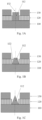
- Figs. 1A to 1C are schematic cross-sectional views of shock wave electrode assembly according to some embodiments of the present disclosure.
- Fig. 2 is a schematic perspective view of a shock wave electrode assembly according to one embodiment of the present disclosure.
- Fig. 3 is an exploded view of the shock wave electrode assembly of Fig. 2 .
- the shock wave electrode assembly 100 includes an inner electrode 110, an outer electrode 130, and an insulating layer 120 located between the inner electrode 110 and the outer electrode 130.
- the surface of the inner electrode 110 is provided with a protruding pin 112, and the insulating layer 120 is provided with a first hole 122.
- the outer electrode 130 is provided with a second hole 132, and a diameter of the second hole 132 is larger than that of the first hole 122.
- the protruding pin 112 extends through the first hole 122 and into the second hole 132, so that a discharge circuit is formed between the inner electrode 110 and the outer electrode 130.
- the inner electrode 110 has a sheet configuration, and the outer electrode 130 and the insulating layer 120 are in annular configurations, as shown in Figs. 2 and 3 .
- the outer electrode 130 and the insulating layer 120 are coaxially arranged, and the outer electrode 130 is sleeved on the insulating layer 120.
- the inner diameter of the outer electrode 130 matches with the outer diameter of the insulating layer 120, thereby reducing the possibility of relative movement.
- the ratio of the thickness of the inner electrode to the thickness of the outer electrode is in a range from 1: 1 to 5: 1. In one embodiment, the ratio of the thickness of the insulating layer to the thickness of the inner electrode is in a range from 1: 1 to 1: 2. According to the embodiment of the present disclosure, the insulating layer mainly functions as a barrier between the inner electrode and the outer electrode. If the insulating layer is thinner, the distance between the inner electrode and the outer electrode will be too close, and electrical conduction will be formed as the breakdown voltage is easily reached. If the insulating layer is relatively thicker, the distance between the inner electrode and the outer electrode will be too far to achieve effective breakdown state.
- the thickness ratio of inner electrode: insulating layer: outer electrode may be 1:1:1.
- the thickness of the insulating layer is related to the dielectric constant of the insulating material.
- the insulating layer having a high dielectric constant has a good insulating performance, and under the same circumstances, a thinner insulating layer can meet the requirements.
- the thickness ratio of inner electrode: insulating layer: outer electrode can be 2:1:2. Therefore, according to the actual situation, insulating materials with different dielectric constants can be used to make insulating layers, and the thickness ratio of inner electrode: insulating layer: outer electrode will change accordingly.
- the materials of the outer electrode and the inner electrode can be conductive metals, such as stainless steel, copper, silver and the like.
- the material of the insulating layer is non-conductive insulating substance, such as polyimide, polytetrafluoroethylene, polyethylene, polypropylene and other polymers.
- the length of the outer electrode 130 can be adjusted accordingly as required, which is not limited by the present disclosure.
- the length of the outer electrode 130 is shorter than that of the insulating layer 120, so that the outer electrode can be better fixed on the insulating layer 120.
- the outline of structure of the outer electrode 130 may be, for example, elliptical, oval, rectangular, triangular, irregular and other geometric structures.
- the outer electrode 130 needs to be sleeved on the insulating layer 120 and form a discharge circuit with the inner electrode 110.
- the protruding pin 112, the first hole 122, and the second hole 132 can also be arranged coaxially, so that a uniform annular gap is formed between the outer electrode and the protruding pin, which is beneficial to uniform discharge.
- the ratio of the diameter of the first hole 122 to the diameter of the second hole 132 is in a range from 1: 2 to 1: 5.
- the direct contact between the two electrodes due to the axial rotation of the outer electrode relative to the insulating layer can be avoided, that is, to ensure that a discharge circuit is formed between the inner electrode and the outer electrode; on the other hand, sufficient discharge effect can be ensured, that is, on the premise that the applied voltage between the inner and outer electrodes exceeds the breakdown voltage of the medium, as the distance between the inner and outer electrodes increases, the energy accumulated between the electrodes becomes higher, the shock wave intensity is greater. Therefore, the appropriate diameter ratio can be adopted according to the shock wave intensity needed for the actual design.
- the radial dimension of the first hole 122 is equal to the maximum radial dimension of the protruding pin 112, so that the protruding pin 112 is fixed in the first hole 122, and thus the inner electrode 110 is connected with the insulating layer 120.
- the first hole 122 plays a role in fixing the position of the protruding pin 112 of the inner electrode 110. If the outer surface of the protruding pin 112 of the inner electrode 110 is separated from the wall of the first hole 122, the protruding pin 112 of the inner electrode 110 is easily not coaxially arranged with the second hole 132 of the outer electrode 130, which affects the actual discharge effect. In addition, the protruding pin 112 will slide relative to the second hole 132 of the outer electrode 130, which will affect the reliability of the shock wave electrode assembly 100.
- the structure of the protruding pin 112 of the inner electrode 110 may be cylindrical (as shown in Fig. 1A ), frustum-shaped (as shown in Fig. 1B ) or conical (as shown in Fig. 1C ), or may be other structures, preferably cylindrical.
- the shape of the protruding pin 112 can affect the discharge mode and energy of the electrodes. Using cylindrical protrusion can not only reduce the threshold breakdown voltage, but also obtain a high electrical energy density. The present disclosure does not limit this, and may depend on the actual situation. According to the actual use, the distance of the gap between the inner electrode 110 and the outer electrode 130 can be adjusted as needed.
- the above-mentioned distance of the gap can be adjusted by changing the shape of the protruding pin 112 of the inner electrode 110, thereby changing the discharge mode and energy of the electrodes.
- the wall of the first hole of the insulating layer may have an inclined surface with a certain angle to ensure matching with the outer surface of the protruding pin with a frustum-shaped or conical structure. Therefore, the protruding pin can be better fixed on the insulating layer 120. It is ensured that the protruding pin 112 will not move relative to the first hole 122 of the insulating layer 120 during the actual operation of the shock wave electrode assembly 100.
- the protruding pin 112 is arranged on the surface of the inner electrode 110, and the protruding pin 112 extends through the first hole 122 and into the second hole 132, so that an annular gap is formed between the outer electrode 130 and the protruding pin 112, so as to form a discharge circuit between the outer electrode 130 and the inner electrode 110.
- the shock wave electrode assembly 100 is placed into a liquid and given an appropriate pulse voltage, the breakdown voltage of the filled liquid can be reached, an electric spark can be emitted, and shock waves can be generated.
- the shock waves propagate through the liquid inside the balloon and impacts the balloon wall and calcified area.
- a common shock wave electrode assembly usually needs relatively high voltages to reach the breakdown voltage of the conductive fluid in the circuit, so as to obtain a shock wave. Higher pulse voltages also lead to demanding internal circuit design of high-voltage generator.
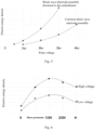
- Fig. 4 is a comparison diagram of the threshold voltage of a shock wave electrode assembly according to an embodiment of the present disclosure and a common shock wave electrode assembly.
- the electrode assembly begins to generate shock waves, that is, the threshold voltage of the common shock wave electrode assembly is determined to be 2.5kV.
- the shock wave electrode assembly of the embodiment of the present disclosure begins to generate shock waves when its voltage exceeds 1.33KV.
- the threshold voltage of the shock wave electrode assembly in the embodiment of the present disclosure is lower, being only 1.33 KV Therefore, it can be concluded that the protruding pin 112 provided on the surface of the inner electrode 110 of the embodiment of the present disclosure extends through the first hole 122 and into the second hole 132, an annular gap is formed between the outer electrode 130 and the protruding pin 112, and a discharge circuit is formed between the outer electrode 130 and the inner electrode 110.
- the design of the shock wave electrode assembly with the protruding pin structure lowers the requirement of the shock wave electrode assembly for pulse voltage, in other words, the shock wave electrode assembly of the embodiment of the present disclosure can generate shock waves at a lower pulse voltage, and the safety of using the shock wave electrode assembly is improved.
- Fig. 5 is a curve graph showing the electric energy density of a shock wave electrode assembly according to an embodiment of the present disclosure and the electric energy density of a common shock wave electrode assembly under different pulse voltages, respectively.
- the pulse voltage is in a range from 1 KV to 3 KV
- the electric energy density of the shock wave electrode assembly in the embodiment of the present disclosure is higher than that of the common shock wave electrode assembly, and the difference between them increases with the increase of pulse voltage.
- the shock wave electrode assembly with the protruding pin structure shows higher electric energy density, thus being able to generate shock waves with higher energy. This will be beneficial to destroying the structure of the calcified lesion attached to the diseased blood vessel wall and improving the therapeutic effect on blocked lesion.
- the height of the protruding pin 112 extending in the second hole 132 is 1/3 to 2/3 of the thickness of the outer electrode 130.
- the shock wave electrode assembly of the present disclosure because the discharge position is the gap between the protruding pin 112 of the inner electrode 110 and the second hole 132, the height of the protruding pin 112 will affect the discharge mode and energy, and an appropriate height can exert the maximum utility of the electrode.
- Fig. 6 is a diagram showing the relationship between the height position of the protruding pin and the electric energy density of the electrode. As shown in Fig.
- 0 means that the height position of the protruding pin 112 is on the surface of the inner electrode 110, and the height of the protruding pin 112 is 0.
- Micro-protrusion means that the height of the protruding pin 112 starts with the surface of the insulating layer 120, and the height of the protruding pin 112 is equal to the thickness of the insulating layer.
- the distance from "0" to the "micro-protrusion” refers to the thickness of the annular insulating layer 120 between the inner electrode 110 and the outer electrode 130.
- the data points are fitted, and the obtained fitting curve shows that the highest point of the electric energy density falls within the range of 1/3-2/3 of the abscissa, that is, the height of the protruding pin 112 extending in the second hole 132 is 1/3-2/3 of the thickness of the outer electrode 130. Under this condition, the electric energy density of the shock wave electrode assembly 100 is the highest, so that the shock wave electrode assembly 100 can exert its best effect.
- Fig. 7 is a schematic diagram of a balloon catheter device according to one embodiment of the present disclosure.
- the balloon catheter device 310 includes an inner tube 320, a balloon 330, an outer tube 350, and a shock wave electrode assembly 200.
- the shock wave electrode assembly 200 includes an inner electrode 210, an outer electrode 230, and an insulating layer 220 located between the inner electrode 210 and the outer electrode 230.
- the surface of the inner electrode 210 is provided with a protruding pin 212
- the insulating layer 220 is provided with a first hole 222
- the outer electrode 230 is provided with a second hole 232.
- the details of the shock wave electrode assembly have been described above and will not be described here.
- the distal end of the inner tube 320 extends through the balloon 330 and is connected with the distal end of the balloon 330, and the shock wave electrode assembly 200 is arranged on the outer surface of the inner tube 320.
- the outer tube 350 is sleeved on the inner tube 320 and connected with the proximal end of the balloon 330.
- the balloon catheter device 310 further includes a lead wire 340 extending along the axial direction of the balloon catheter device 310, and the lead wire 340 includes a first lead wire 340A and a second lead wire 340B (see Fig. 9A ), the first lead wire 340A is connected with the inner electrode 210, and the second lead wire 340B is connected with the outer electrode 230.
- the two lead wires extend along the axial direction of the balloon catheter device 310, and are connected with a high-voltage generator (not shown) through connecting lead wires M (not shown), respectively.
- the current is transmitted to the inner electrode 210 through the first lead wire 340A, and the inner electrode 210 forms a circuit with the outer electrode 230 through the filled conductive fluid.
- the high-voltage pulse causes the breakdown of the conductive fluid and generates shock waves in the axial direction of the first hole 222. Then, the current is transmitted to the outer electrode 230 and returned to the high-voltage generator along the second lead wire 340B.
- the surface of the inner electrode 210 is provided with the protruding pin 212, and a discharge circuit is formed between the outer electrode 230 and the protruding pin 212 of the inner electrode 210.
- the shock wave electrode assembly 200 When the shock wave electrode assembly 200 is placed into a liquid and given an appropriate pulse voltage, the breakdown voltage of the filled liquid can be reached, an electric spark can be emitted, and shock waves can be generated.
- the shock wave propagates through the liquid inside the balloon and impacts the balloon wall and calcified area. Repeated pulses can destroy the structure of calcified lesions and expand narrowed blood vessels without damaging the surrounding soft tissues, which can avoid the problem of blood vessel wall damage caused by balloon expansion in traditional angioplasty.
- the shock wave electrode assembly of the balloon catheter device in the embodiment of the present disclosure can generate shock waves at a lower pulse voltage, thereby improving the safety of using the balloon catheter device.
- the shock wave electrode assembly with the protruding pin structure shows higher electric energy density, so the balloon catheter device in the embodiment of the present disclosure can more effectively destroy the structure of the calcified lesion attached to the diseased blood vessel wall and improve the therapeutic effect on the blocked lesion through the generated shock waves with higher energy.
- Fig. 8A is a schematic cross-sectional view of a balloon catheter device according to an embodiment of the present disclosure.
- the positional relationship of the components of the shock wave electrode assembly in the balloon catheter device is further given in combination with the assembling process of the inner electrode 210, the insulating layer 220, and the outer electrode 230.
- Fig. 3 Fig. 7 and Fig.
- the inner electrode 210 is placed on the surface of the inner tube 320, then the insulating layer 220 with the first hole 222 is sleeved on the inner tube 320, and the insulating layer 220 is moved to align the first hole 222 with the protruding pin 212, and the protruding pin 212 is fixed in the first hole 222 by pressing, so that the inner electrode 210 can be fixed.
- the inner tube 320 and the insulating layer 220 can be further fixed with glue.
- the outer electrode 230 is sleeved on the insulating layer 220, and the second hole 232 is aligned with the first hole 222 and the protruding pin 212, so that the protruding pin 212, the first hole 222, and the second hole 232 are coaxial, and the outer electrode 230 can be fixed on the insulating layer 220 with glue.
- the outer electrode 230 includes a plurality of second holes 232
- the insulating layer 220 includes a plurality of first holes 222
- the balloon catheter device includes a plurality of inner electrodes 210.
- the number of the inner electrodes 210, the number of the first holes 222, and the number of the second holes 232 are equal, so that the balloon catheter device can have a plurality of shock wave electrode assemblies.
- a structure with multiple shock wave electrode assemblies can be used to construct multiple discharge regions by the balloon catheter device.
- the ability of the balloon catheter device to treat multiple calcified lesions at the same time can be improved, on the other hand, the uniformity of shock wave distribution in the circumferential space of the inner tube can be improved, which is beneficial to the treatment of calcified lesions.
- Figs. 8A to 8C show schematic cross-sectional views of balloon catheter devices provided with one, two or three shock wave electrode assemblies.
- the distribution of the shock wave electrode assembly in the circumferential direction of the inner tube 320 can be adjusted according to the actual position distribution of the calcified lesions to be treated, which is not limited by the present disclosure.
- the balloon catheter device 310 includes a plurality of shock wave electrode assemblies 200 arranged at intervals along the axial direction of the inner tube 320. If there are multiple calcified lesions to be treated, and they are separated by a certain distance, it is inconvenient to transport the balloon catheter device to different calcified lesions for treatment one by one in the case where the balloon catheter device adopts a single shock wave electrode assembly 200. Therefore, in view of the above situation, a balloon catheter device with a plurality of shock wave electrode assemblies 200 arranged at intervals along the axial direction of the inner tube can be adopted.
- Fig. 9A shows a schematic diagram of a balloon catheter device with two shock wave electrode assemblies 200. Meanwhile, the distribution of different shock wave electrode assemblies 200 in the axial direction of the inner tube 320 is adjusted according to the actual position distribution of the calcified lesions to be treated, which is not limited by the present disclosure.
- a plurality of shock wave electrode assemblies are arranged in series.
- a plurality of shock wave electrode assemblies 200 can be arranged in the balloon catheter device, and the shock wave electrode assemblies 200 are connected in series to generate shock waves in the axial direction of the first hole of each shock wave electrode assembly 200.
- the inside of the balloon can be filled with conductive fluid through the liquid passage cavity.
- the shock wave electrode assemblies 200 are arranged on the outer surface of the inner tube 320 at a certain distance, and transmits current by connecting a plurality of lead wires. The arrangement in series of the two shock wave electrode assemblies is shown in Fig. 9A .
- the first lead wire 340A is connected to the protruding pin of the inner electrode of the shock wave electrode assembly 200A which forms a circuit with the outer electrode of the shock wave electrode assembly 200A through the conductive fluid, and a first shock wave is generated in the axial direction of the first hole of the shock wave electrode assembly 200A.
- the second lead wire 340B is arranged to connect the outer electrode of the shock wave electrode assembly 200A with the inner electrode of the shock wave electrode assembly 200B, and the inner electrode of the shock wave electrode assembly 200B forms a circuit with the outer electrode of the shock wave electrode assembly 200B through the conductive fluid.
- a second shock wave is generated in the axial direction of the first hole of the shock wave electrode assembly 200B.
- the third lead wire 340C connected with the outer electrode of the shock wave electrode assembly 200B extends along the axial direction of the balloon catheter device 310 and is connected with the connecting lead wire M.
- multiple shock wave electrode assemblies can be arranged inside the balloon to generate shock waves in the axial direction of the first hole of the shock wave electrode assembly 200.
- the threshold voltage, for generating the shock waves, of the shock wave electrode assembly of the balloon catheter device according to the embodiment of the present disclosure is lower than that of a common shock wave electrode assembly, which lowers requirements of the shock wave electrode assembly on pulse voltage and improves the safety of the use of the balloon catheter device; and under the same pulse voltage, the shock wave electrode assembly with the protruding pin structure can generate higher intensity shock wave.
- a plurality of shock wave electrode assemblies 200 are arranged in the same circumferential direction of the inner tube 320, or are arranged at an angle in the circumferential direction.
- the shock wave is generated at the gap between the outer electrode 230 and the protruding pin 212.
- the relative arrangement direction of the shock wave electrode assemblies 200 will affect the intensity and distribution of shock waves generated by the entire balloon.
- a plurality of shock wave electrode assemblies 200 may be arranged in the same circumferential direction of the inner tube 320 or at an angle in the circumferential direction according to the position of calcified lesions to be treated in the operation, which is not limited by the present disclosure.
- Fig. 9B is a schematic diagram of a balloon catheter device with three shock wave electrode assemblies 200 arranged at 90 degrees and at intervals along the circumferential direction of the inner tube 320, that is, the projections of the three shock wave electrode assemblies on the projection plane perpendicular to the central axis of the inner tube are not coincident.
- Fig. 9C is a schematic diagram of the balloon catheter device with three shock wave electrode assemblies 200 facing the same direction in the circumferential direction and arranged at a certain distance in the axial direction, that is, the projections of the three shock wave electrode assemblies on the projection plane perpendicular to the central axis of the inner tube coincide.
- a plurality of shock wave electrode assemblies are adopted to enable the balloon catheter device to treat a plurality of calcified lesions at the same time.
- the positions of a plurality of shock wave electrode assemblies 200 can be arranged correspondingly according to the positions of the calcified lesions to be treated, such as in the same circumferential direction or at intervals of a certain angle, so as to improve the treatment effect on the blocked lesions, save the operation time, and improve the efficiency.
- the inventor also proposed a medical apparatus, which includes a high-voltage generator and a balloon catheter device 310, a proximal end of a lead wire 340 of the balloon catheter device 310 is connected with the high-voltage generator.
- the high-voltage generator needs to meet the following parameters: the pulse voltage of the high-voltage generator is in a range from 500 V to10 kV, and the pulse voltage width is in a range from 200 ns to 20 ⁇ s, the pulse current of the high-voltage generator is in a range from 50 A to 400 A, and the pulse current width is in a range from 10 ns to 2 ⁇ s.
- the sound pressure intensity of the shock wave generated by each shock wave electrode assembly is in a range from 2 MPa to 20 MPa, and the discharge frequency is in a range from 0.1 Hz to 10 Hz.
- the shock wave generated by the shock wave electrode assembly propagates through the liquid inside the balloon and impacts the balloon wall and calcified area. Repeated pulses can destroy the structure of calcified lesions and expand narrowed blood vessels without damaging the surrounding soft tissues, which can avoid the problem of blood vessel wall damage caused by balloon expansion in traditional angioplasty. Therefore, the medical apparatus of the embodiment of the present disclosure can more effectively destroy the structure of the calcified lesion attached to the diseased blood vessel wall, and improve the therapeutic effect on the blocked lesion.
- the shock wave electrode assembly of the present disclosure has a lower threshold pulse voltage and can complete discharge at a lower pulse voltage, thereby reducing the requirements of the shock wave electrode assembly on pulse voltage. Compared with the common shock wave electrode assembly, at the same pulse voltage, the shock wave electrode assembly of the present disclosure has higher electrical energy density, thereby being able to generate higher energy shock waves.
Landscapes
- Health & Medical Sciences (AREA)
- Life Sciences & Earth Sciences (AREA)
- Engineering & Computer Science (AREA)
- Heart & Thoracic Surgery (AREA)
- Animal Behavior & Ethology (AREA)
- Veterinary Medicine (AREA)
- Public Health (AREA)
- Surgery (AREA)
- Biomedical Technology (AREA)
- General Health & Medical Sciences (AREA)
- Vascular Medicine (AREA)
- Nuclear Medicine, Radiotherapy & Molecular Imaging (AREA)
- Molecular Biology (AREA)
- Medical Informatics (AREA)
- Orthopedic Medicine & Surgery (AREA)
- Mechanical Engineering (AREA)
- Child & Adolescent Psychology (AREA)
- Biophysics (AREA)
- Pulmonology (AREA)
- Anesthesiology (AREA)
- Hematology (AREA)
- Surgical Instruments (AREA)
- Media Introduction/Drainage Providing Device (AREA)
Applications Claiming Priority (2)
| Application Number | Priority Date | Filing Date | Title |
|---|---|---|---|
| CN202111323375.8A CN113855163B (zh) | 2021-11-09 | 2021-11-09 | 一种冲击波电极组件、球囊导管装置以及医疗设备 |
| PCT/CN2022/129425 WO2023083084A1 (fr) | 2021-11-09 | 2022-11-03 | Ensemble électrode à ondes de choc, appareil de cathéter à ballonnet et dispositif médical |
Publications (2)
| Publication Number | Publication Date |
|---|---|
| EP4431032A1 true EP4431032A1 (fr) | 2024-09-18 |
| EP4431032A4 EP4431032A4 (fr) | 2025-11-12 |
Family
ID=78987551
Family Applications (1)
| Application Number | Title | Priority Date | Filing Date |
|---|---|---|---|
| EP22891879.3A Pending EP4431032A4 (fr) | 2021-11-09 | 2022-11-03 | Ensemble électrode à ondes de choc, appareil de cathéter à ballonnet et dispositif médical |
Country Status (4)
| Country | Link |
|---|---|
| EP (1) | EP4431032A4 (fr) |
| JP (1) | JP2024541339A (fr) |
| CN (2) | CN113855163B (fr) |
| WO (1) | WO2023083084A1 (fr) |
Families Citing this family (18)
| Publication number | Priority date | Publication date | Assignee | Title |
|---|---|---|---|---|
| DE112022005004T5 (de) * | 2021-10-19 | 2024-08-01 | Shockwave Medical, Inc. | Intravaskulärer lithotripsie-katheter mit interferierenden stosswellen |
| CN113855163B (zh) * | 2021-11-09 | 2024-03-22 | 上海蓝帆博元医疗科技有限公司 | 一种冲击波电极组件、球囊导管装置以及医疗设备 |
| CN114366237B (zh) * | 2022-01-10 | 2023-11-24 | 深圳市赛禾医疗技术有限公司 | 一种电极结构及球囊 |
| CN114533198A (zh) * | 2022-02-24 | 2022-05-27 | 上海蓝帆博元医疗科技有限公司 | 一种冲击波球囊导管装置以及医疗设备 |
| CN114903558B (zh) * | 2022-05-19 | 2023-11-10 | 杭州天路医疗器械有限公司 | 一种用于体内腔道塑形的冲击波发生装置 |
| CN114886503A (zh) * | 2022-05-27 | 2022-08-12 | 深圳英美达医疗技术有限公司 | 一种基于尖端放电的冲击波球囊导管 |
| CN115051691A (zh) * | 2022-06-22 | 2022-09-13 | 上海蓝帆博元医疗科技有限公司 | 一种高压脉冲发生装置及冲击波发生系统 |
| CN114983519B (zh) * | 2022-07-01 | 2025-07-25 | 深圳市赛禾医疗技术有限公司 | 环状放电电极对阵列及冲击波球囊导管 |
| CN115068060A (zh) * | 2022-08-18 | 2022-09-20 | 深圳北芯医疗科技有限公司 | 冲击波发生组件及球囊导管 |
| CN115463317B (zh) * | 2022-08-23 | 2023-08-29 | 深圳市赛禾医疗技术有限公司 | 一种冲击波球囊导管 |
| CN115778485B (zh) * | 2022-12-02 | 2023-11-07 | 鑫易舟(上海)医疗器械有限公司 | 冲击波发生装置、冲击波发生系统和方法 |
| CN118267045A (zh) * | 2022-12-29 | 2024-07-02 | 上海蓝帆博元医疗科技有限公司 | 一种冲击波电极组件以及球囊导管装置 |
| CN116138840B (zh) * | 2023-01-19 | 2025-12-02 | 上海科亚方舟医疗科技有限公司 | 电极组件、球囊导管和球囊震波设备 |
| CN116392200B (zh) * | 2023-04-10 | 2025-12-23 | 飞依诺科技股份有限公司 | 冲击波电极组件、球囊导管及医疗设备 |
| CN117297712A (zh) * | 2023-09-06 | 2023-12-29 | 深圳高性能医疗器械国家研究院有限公司 | 电极球囊导管 |
| CN117281580B (zh) * | 2023-11-27 | 2024-03-15 | 沛嘉医疗科技(苏州)有限公司 | 一种用于处理组织钙化的电极装置及冲击波装置 |
| CN118356232B (zh) * | 2024-06-18 | 2024-11-15 | 苏州中荟医疗科技有限公司 | 一种能量可叠加释放的电极导管结构 |
| CN119074132A (zh) * | 2024-08-30 | 2024-12-06 | 复旦大学附属中山医院 | 一种穿透高阻力病变的冲击波导管 |
Family Cites Families (20)
| Publication number | Priority date | Publication date | Assignee | Title |
|---|---|---|---|---|
| DE2747031C2 (de) * | 1977-10-19 | 1981-10-08 | Ivan Vasil'evič Parfinenko | Vorrichtung zum Zerstören von Konkrementen in den harnableitenden Wegen |
| US4476862A (en) * | 1980-12-08 | 1984-10-16 | Pao David S C | Method of scleral marking |
| US5254121A (en) * | 1992-05-22 | 1993-10-19 | Meditron Devices, Inc. | Method and device for removing concretions within human ducts |
| US7087061B2 (en) * | 2002-03-12 | 2006-08-08 | Lithotech Medical Ltd | Method for intracorporeal lithotripsy fragmentation and apparatus for its implementation |
| US8888788B2 (en) * | 2012-08-06 | 2014-11-18 | Shockwave Medical, Inc. | Low profile electrodes for an angioplasty shock wave catheter |
| US9333000B2 (en) * | 2012-09-13 | 2016-05-10 | Shockwave Medical, Inc. | Shockwave catheter system with energy control |
| CN105392435B (zh) * | 2013-07-22 | 2018-11-09 | 波士顿科学国际有限公司 | 具有扭绞球囊的肾神经消融导管 |
| US10850078B2 (en) * | 2014-12-30 | 2020-12-01 | The Spectranetics Corporation | Electrically-induced fluid filled balloon catheter |
| WO2017087195A1 (fr) * | 2015-11-18 | 2017-05-26 | Shockwave Medical, Inc. | Électrodes d'onde de choc |
| US10357264B2 (en) * | 2016-12-06 | 2019-07-23 | Shockwave Medical, Inc. | Shock wave balloon catheter with insertable electrodes |
| US11020135B1 (en) * | 2017-04-25 | 2021-06-01 | Shockwave Medical, Inc. | Shock wave device for treating vascular plaques |
| NL2019807B1 (en) * | 2017-10-26 | 2019-05-06 | Boston Scient Scimed Inc | Shockwave generating device |
| US10709462B2 (en) * | 2017-11-17 | 2020-07-14 | Shockwave Medical, Inc. | Low profile electrodes for a shock wave catheter |
| US11266817B2 (en) * | 2018-10-25 | 2022-03-08 | Medtronic Vascular, Inc. | Cavitation catheter |
| DE102018129435A1 (de) * | 2018-11-22 | 2020-05-28 | Biotronik Ag | Multifunktionale Verwendung einer Elektrodenstruktur eines Ballons eines Ballonkathetersystems |
| CN112220526B (zh) * | 2020-12-10 | 2021-04-02 | 上海百心安生物技术股份有限公司 | 一种脉冲球囊及使用方法 |
| CN112971914B (zh) * | 2021-02-09 | 2022-08-02 | 哈尔滨医科大学 | 一种血管内灌注冲击波碎石导管系统 |
| CN112932651B (zh) * | 2021-03-24 | 2025-02-21 | 上海微创旋律医疗科技有限公司 | 电极部件及电极球囊导管 |
| CN113117220B (zh) * | 2021-04-14 | 2023-03-21 | 深圳市赛禾医疗技术有限公司 | 一种药物球囊导管、药物球囊导管系统及其控制方法 |
| CN113855163B (zh) * | 2021-11-09 | 2024-03-22 | 上海蓝帆博元医疗科技有限公司 | 一种冲击波电极组件、球囊导管装置以及医疗设备 |
-
2021
- 2021-11-09 CN CN202111323375.8A patent/CN113855163B/zh active Active
- 2021-11-09 CN CN202410218048.3A patent/CN117838247A/zh active Pending
-
2022
- 2022-11-03 JP JP2024527564A patent/JP2024541339A/ja active Pending
- 2022-11-03 EP EP22891879.3A patent/EP4431032A4/fr active Pending
- 2022-11-03 WO PCT/CN2022/129425 patent/WO2023083084A1/fr not_active Ceased
Also Published As
| Publication number | Publication date |
|---|---|
| WO2023083084A1 (fr) | 2023-05-19 |
| CN113855163B (zh) | 2024-03-22 |
| EP4431032A4 (fr) | 2025-11-12 |
| JP2024541339A (ja) | 2024-11-08 |
| CN117838247A (zh) | 2024-04-09 |
| CN113855163A (zh) | 2021-12-31 |
Similar Documents
| Publication | Publication Date | Title |
|---|---|---|
| EP4431032A1 (fr) | Ensemble électrode à ondes de choc, appareil de cathéter à ballonnet et dispositif médical | |
| WO2023160505A1 (fr) | Dispositif de cathéter à ballonnet à ondes de choc et appareil médical | |
| CN113842190B (zh) | 电极球囊导管 | |
| CN115778485B (zh) | 冲击波发生装置、冲击波发生系统和方法 | |
| US20140257323A1 (en) | Unfocused electrohydraulic lithotripter | |
| CN112220526B (zh) | 一种脉冲球囊及使用方法 | |
| CN217853181U (zh) | 一种冲击波球囊导管装置以及医疗设备 | |
| CN114366237B (zh) | 一种电极结构及球囊 | |
| CN115463317B (zh) | 一种冲击波球囊导管 | |
| CN114869401A (zh) | 冲击波装置 | |
| CA3031532A1 (fr) | Appareil generateur d'onde de choc electrohydraulique (eh) a impulsion rapide presentant une duree de vie d'electrode amelioree | |
| CN112869825A (zh) | 一种用于产生震波的电极装置及使用方法 | |
| CN114869400A (zh) | 用于治疗心脏瓣膜或血管钙化的冲击波装置用电极和冲击波装置 | |
| CN119235410B (zh) | 冲击波电极及冲击波盲端球囊导管 | |
| CN115068060A (zh) | 冲击波发生组件及球囊导管 | |
| CN218979093U (zh) | 一种冲击波电极组件以及球囊导管装置 | |
| EP4643795A1 (fr) | Ensemble électrode à ondes de choc et dispositif de cathéter à ballonnet | |
| HK40116656A (en) | Shock wave electrode assembly, balloon catheter apparatus, and medical device | |
| CN114795386B (zh) | 冲击波发生组件、电极球囊导管及制作方法 | |
| EP4265203A1 (fr) | Cathéter à ballonnet à ondes de pression et dispositif médical | |
| WO2025246600A1 (fr) | Dispositif auto-expansible d'excitation à impulsions et procédé de traitement | |
| CN118614988A (zh) | 一种电极装置、形成方法及冲击波系统 | |
| CN116077136A (zh) | 改进型冲击波球囊 | |
| CN217408905U (zh) | 冲击波发生组件及电极球囊导管 | |
| CN116158807A (zh) | 冲击波球囊导管 |
Legal Events
| Date | Code | Title | Description |
|---|---|---|---|
| STAA | Information on the status of an ep patent application or granted ep patent |
Free format text: STATUS: THE INTERNATIONAL PUBLICATION HAS BEEN MADE |
|
| PUAI | Public reference made under article 153(3) epc to a published international application that has entered the european phase |
Free format text: ORIGINAL CODE: 0009012 |
|
| STAA | Information on the status of an ep patent application or granted ep patent |
Free format text: STATUS: REQUEST FOR EXAMINATION WAS MADE |
|
| 17P | Request for examination filed |
Effective date: 20240607 |
|
| AK | Designated contracting states |
Kind code of ref document: A1 Designated state(s): AL AT BE BG CH CY CZ DE DK EE ES FI FR GB GR HR HU IE IS IT LI LT LU LV MC ME MK MT NL NO PL PT RO RS SE SI SK SM TR |
|
| DAV | Request for validation of the european patent (deleted) | ||
| DAX | Request for extension of the european patent (deleted) | ||
| REG | Reference to a national code |
Ref country code: HK Ref legal event code: DE Ref document number: 40116656 Country of ref document: HK |
|
| A4 | Supplementary search report drawn up and despatched |
Effective date: 20251010 |
|
| RIC1 | Information provided on ipc code assigned before grant |
Ipc: A61B 17/22 20060101AFI20251006BHEP Ipc: A61M 25/10 20130101ALI20251006BHEP |