EP4431055A1 - Reinigungs- und pflegegerät - Google Patents
Reinigungs- und pflegegerät Download PDFInfo
- Publication number
- EP4431055A1 EP4431055A1 EP22891678.9A EP22891678A EP4431055A1 EP 4431055 A1 EP4431055 A1 EP 4431055A1 EP 22891678 A EP22891678 A EP 22891678A EP 4431055 A1 EP4431055 A1 EP 4431055A1
- Authority
- EP
- European Patent Office
- Prior art keywords
- boss
- drive shaft
- frame
- cleaning
- caring
- Prior art date
- Legal status (The legal status is an assumption and is not a legal conclusion. Google has not performed a legal analysis and makes no representation as to the accuracy of the status listed.)
- Pending
Links
Images




Classifications
-
- A—HUMAN NECESSITIES
- A61—MEDICAL OR VETERINARY SCIENCE; HYGIENE
- A61C—DENTISTRY; APPARATUS OR METHODS FOR ORAL OR DENTAL HYGIENE
- A61C17/00—Devices for cleaning, polishing, rinsing or drying teeth, teeth cavities or prostheses; Saliva removers; Dental appliances for receiving spittle
- A61C17/16—Power-driven cleaning or polishing devices
- A61C17/22—Power-driven cleaning or polishing devices with brushes, cushions, cups, or the like
- A61C17/225—Handles or details thereof
-
- A—HUMAN NECESSITIES
- A61—MEDICAL OR VETERINARY SCIENCE; HYGIENE
- A61C—DENTISTRY; APPARATUS OR METHODS FOR ORAL OR DENTAL HYGIENE
- A61C17/00—Devices for cleaning, polishing, rinsing or drying teeth, teeth cavities or prostheses; Saliva removers; Dental appliances for receiving spittle
- A61C17/16—Power-driven cleaning or polishing devices
- A61C17/22—Power-driven cleaning or polishing devices with brushes, cushions, cups, or the like
- A61C17/32—Power-driven cleaning or polishing devices with brushes, cushions, cups, or the like reciprocating or oscillating
- A61C17/34—Power-driven cleaning or polishing devices with brushes, cushions, cups, or the like reciprocating or oscillating driven by electric motor
- A61C17/3409—Power-driven cleaning or polishing devices with brushes, cushions, cups, or the like reciprocating or oscillating driven by electric motor characterized by the movement of the brush body
- A61C17/3418—Rotation around the axis of the toothbrush handle
-
- A—HUMAN NECESSITIES
- A46—BRUSHWARE
- A46B—BRUSHES
- A46B13/00—Brushes with driven brush bodies or carriers
- A46B13/02—Brushes with driven brush bodies or carriers power-driven carriers
-
- A—HUMAN NECESSITIES
- A61—MEDICAL OR VETERINARY SCIENCE; HYGIENE
- A61C—DENTISTRY; APPARATUS OR METHODS FOR ORAL OR DENTAL HYGIENE
- A61C17/00—Devices for cleaning, polishing, rinsing or drying teeth, teeth cavities or prostheses; Saliva removers; Dental appliances for receiving spittle
- A61C17/16—Power-driven cleaning or polishing devices
- A61C17/22—Power-driven cleaning or polishing devices with brushes, cushions, cups, or the like
- A61C17/32—Power-driven cleaning or polishing devices with brushes, cushions, cups, or the like reciprocating or oscillating
- A61C17/34—Power-driven cleaning or polishing devices with brushes, cushions, cups, or the like reciprocating or oscillating driven by electric motor
Definitions
- the present invention relates to a cleaning and caring appliance, such as an electric toothbrush, and in particular to a cleaning and caring appliance, such as an electric toothbrush, provided with a connecting rod mechanism that converts a rotational motion of a drive device into reciprocating rotation of a drive shaft.
- the electric toothbrush includes a handle and a brush head which is attached to a drive shaft extending from the handle.
- a rotating motor is mounted inside the handle.
- a drive force provided by the rotating motor is output by means of an output shaft of the rotating motor, and is converted into reciprocating rotation of the drive shaft by means of a planar four-connecting-rod structure so as to enable the brush head on the drive shaft to swing in a reciprocating motion.
- the longitudinal axis of the rotating motor and the longitudinal axis of the drive shaft directly attached to the brush head are in parallel and offset from each other by an offset distance that is usually 5 mm or more.
- the brush head of the electric toothbrush is eccentrically arranged relative to the central longitudinal axis of the handle.
- the cleaning and caring appliance includes: a housing, in which a chamber is formed; a motor, which includes an output shaft having a first axis, the output shaft performing a rotational motion, the motor being arranged in the chamber, and a driving wheel being provided on the output shaft; a drive shaft, which has a second axis and extends out of the chamber; and a connecting rod mechanism, which is connected to both the driving wheel of the output shaft and the drive shaft and is configured to convert the rotational motion of the output shaft around the first axis into reciprocating rotation of the drive shaft around the second axis; wherein the cleaning and caring appliance includes a frame arranged adjacent to the motor in the housing, the frame including a frame bottom wall and a first boss and a second boss which protrude from the frame bottom wall, the drive shaft being accommodated in a first boss cavity formed by the first boss, the second boss being provided with a hole portion, the drive shaft being accommodated in the hole portion
- the second boss is overlapped above the first boss, such that the first axis of the output shaft is substantially aligned with the second axis of the drive shaft. That is, the longitudinal axis of the output shaft and the longitudinal axis of the drive shaft are in a straight line, or are in parallel and offset from each other by a distance of less than 1 mm, and a distal end of the drive shaft is located directly above the output shaft.
- both the output shaft and the drive shaft can be retained by means of one frame when the axis of the output shaft of the motor is substantially aligned with the axis of the drive shaft.
- a boss hole bottom is provided between the first boss and the second boss, the boss hole bottom abuts against an end of the drive shaft, and the boss hole bottom is integrally formed with at least one of the first boss and the second boss.
- a driving wheel is provided on the output shaft of the motor, and at least part of the driving wheel is accommodated in the first boss cavity.
- the connecting rod mechanism further includes: a driven wheel, which is in gear engagement with the driving wheel; a driven wheel eccentric rod connected to the driven wheel, with a central axis of the driven wheel eccentric rod being eccentrically arranged relative to an axis of rotation of the driven wheel; a connecting rod, which has one end connected to the driven wheel eccentric rod; a drive shaft eccentric rod connected to the other end of the connecting rod; and a drive shaft connection rod, which has one end connected to the drive shaft eccentric rod and the other end fixed to the drive shaft.
- the first boss includes a first boss wall circumferentially surrounding the driving wheel, the first boss wall including a notch portion where the driven wheel engages with the driving wheel.
- the other end of the drive shaft connection rod is fixed to the drive shaft above the second boss.
- the frame further includes a frame outer wall which extends from and is integrally formed with the frame bottom wall and surrounds the connecting rod mechanism, wherein the frame bottom wall is provided with a first opening between the first boss and the outer wall, and the first opening accommodates one end of the driven wheel eccentric rod.
- the second boss is formed separately from the first boss, and the second boss is snap-fitted onto the first boss.
- the frame bottom wall is provided with a boss bottom hole on one side of the first boss close to the motor, and the output shaft of the motor extends into the first boss cavity through the boss bottom hole.
- the frame is provided with the two overlapping bosses for mounting the connecting rod mechanism and the drive shaft, thereby providing a compact arrangement structure.
- the longitudinal axis of the brush head and the longitudinal axis of the handle of the electric toothbrush can be substantially in a straight line, and the drive shaft is kept substantially aligned with the output shaft of the motor by means of one frame, achieving accurate positioning and convenient installation.
- proximal end/side refers to an end or a side close to the position where a cleaning action force acts when the cleaning and caring appliance is in use
- distal end/side refers to the end or side away from the position where the cleaning action force acts when the cleaning and caring appliance is in use.
- FIG. 1 shows a perspective view of a cleaning and caring appliance according to a preferred embodiment of the present invention.
- the cleaning and caring appliance is an electric toothbrush 100.
- the electric toothbrush 100 mainly includes a handle portion 1 and a brush head 2 detachably mounted on the handle portion 1.
- the handle portion 1 includes a handle housing 6 and functional components mounted in the handle housing 6.
- the brush head 2 is provided with a cleaning element 4, such as bristles.
- a switch portion 3 is arranged in the middle of the handle housing 6 slightly close to a proximal side. When a user presses the switch portion 3, the functional components inside the electric toothbrush 100 can be powered to enable the brush head 2 to reciprocate.
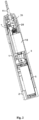
- FIG. 2 further shows an internal structure of the electric toothbrush 100 according to a preferred embodiment of the present invention.
- the electric toothbrush 100 includes, from a distal end to a proximal end in a longitudinal direction of the electric toothbrush 100, a battery 5, a circuit board 8, a motor 10, a connecting rod mechanism 7 and a drive shaft 11, which are arranged in a chamber formed by the handle housing 6.
- the handle housing 6 is internally provided with a frame 20 that accommodates and retains the connecting rod mechanism 7 and the drive shaft 11 as well as a frame cover 26 that is assembled with the frame 20 on a proximal side of the frame 20.
- the battery 5 is arranged on a distal side of the chamber of the handle portion 1 to supply power for the motor 10 of the electric toothbrush 100.
- the circuit board 8 is arranged between the battery 5 and the motor 10, and is provided with a switch and related control devices.
- the circuit board 8 is arranged at a distal side of the motor 10, and the output shaft of the motor 10 extends toward the connecting rod mechanism 7 on the proximal side of the motor 10.
- the output shaft can rotate around its longitudinal axis L 2 (a first axis) when the motor 10 is actuated.
- the connecting rod mechanism 7 is configured to be connected to both the driving wheel 16 on the output shaft of the motor 10 and the drive shaft 11, for converting the rotational motion of the output shaft into reciprocating rotation of the drive shaft 11 around its longitudinal axis Li (a second axis).
- the drive shaft 11 connected to the connecting rod mechanism 7 partially extends out of the chamber formed by the handle housing 6 of the handle so as to connect the brush head 2.
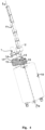
- FIG. 3 shows a plan view of the connecting rod mechanism 7 according to a preferred embodiment of the present invention
- FIG. 4 shows a perspective view of the motor 10 and the connecting rod mechanism 7 according to a preferred embodiment of the present invention.
- the connecting rod mechanism 7 includes a driven wheel 15, a driven wheel eccentric rod 17, a connecting rod 14, a drive shaft eccentric rod 13 and a drive shaft connection rod 12, which form a four-connecting-rod mechanism.
- the driving wheel 16 is a cylindrical gear which is mounted on the output shaft of the motor 10, the axis of rotation of the driving wheel 16 is in line with the longitudinal axis L 2 of the output shaft, and the output shaft of the motor 10 rotates to drive the driving wheel 16 to rotate.
- the driven wheel 15 is also a cylindrical gear which engages with the driving wheel 16, and the axis of rotation of the driven wheel 15 is parallel to but separated from the axis of rotation of the driving wheel 16 by a certain distance.
- the driven wheel eccentric rod 17 in the connecting rod mechanism 7 is arranged substantially in the longitudinal direction, and the driven wheel eccentric rod 17 is connected to both the driven wheel 15 and the connecting rod 14.
- the connecting rod 14 is arranged transversely to the longitudinal direction, and is connected to both the driven wheel eccentric rod 17 and the drive shaft eccentric rod 13. As shown in FIG. 5 , the connecting rod 14 is provided with a first hole 18 and a second hole 19; one end of the driven wheel eccentric rod 17 is inserted into the first hole 18, and the center of the first hole 18 is offset relative to the center of rotation of the driven wheel 15; and the driven wheel eccentric rod 17 is configured to connect the center-biased first hole 18 and the driven wheel 15, thus forming a drive arm of the planar four-connecting-rod mechanism.
- the drive shaft eccentric rod 13 is connected to both the connecting rod 14 and the drive shaft connection rod 12. The distal end of the drive shaft eccentric rod 13 is inserted into the second hole 19 of the connecting rod 14.
- the drive shaft eccentric rod 13 is also arranged substantially in the longitudinal direction and is offset to one side of the drive shaft 11.
- the drive shaft connection rod 12 is connected to both the drive shaft eccentric rod 13 and the drive shaft 11. Similar to the connecting rod 14, the drive shaft connection rod 12 is also provided with a first hole and a second hole separated by a certain distance, the drive shaft eccentric rod 13 being inserted into the first hole, and the distal end of the drive shaft 11 being inserted through the second hole.
- the central axis of the second hole of the drive shaft connection rod 12 of the connecting rod mechanism 7 is substantially aligned with the axis of rotation of the driving wheel 16, that is, the longitudinal axis Li of the drive shaft 11 inserted into the second hole is substantially aligned with the longitudinal axis of the output shaft connected to the motor 10.
- one axis being "substantially aligned" with another axis means that the two axes are in a straight line or are in parallel and offset by a distance of less than 1 mm.
- FIG. 5 shows a schematic diagram of a four-connecting-rod device composed of the connecting rod mechanism 7 described above.
- point O is the center of the drive shaft 11
- point A is the center of the second hole of the connecting rod 14
- point B is the center of the first hole of the connecting rod 14, i.e., the position of the central axis of the driven wheel eccentric shaft
- point C is the center of rotation of the driven wheel 15.
- the output shaft of the motor 10 rotates to drive the driving wheel 16 to rotate
- the driving wheel 16 engages with and drives the driven wheel 15 to rotate around the point C
- the driven wheel 15 is fixed to the driven wheel eccentric rod 17, and the driven wheel 15 rotates to drive the driven wheel eccentric rod 17 to rotate around the point C.
- the driven wheel eccentric rod 17 rotates to drive the connecting rod 14, the drive shaft eccentric rod 13 and the drive shaft connection rod 12 to perform reciprocating rotation around the point C, so as to drive the drive shaft 11 to reciprocate around the point O, so as to allow the brush head 2 mounted on the drive shaft 11 to reciprocate.
- the drive shaft 11, the drive shaft connection rod 12, the connecting rod 14, the driven wheel 15 and the driven wheel eccentric rod 17 form a planar four-connecting-rod structure. As shown in FIG.
- a connecting line from the center C of the driven wheel 15 to the center of the hole 18 of the connecting rod 14 forms a drive arm of the planar four-connecting-rod structure, and the drive arm may continuously rotate 360 degrees, thus achieving the reciprocating rotation of the drive shaft 11 around the longitudinal axis.
- the frame 20 is arranged adjacent to the motor 10 in the housing.
- the frame 20 includes a frame bottom wall, a frame outer wall, and a first boss 24 and a second boss 23 which are arranged inside the frame outer wall and protrude from the frame bottom wall substantially in the longitudinal direction, wherein the first boss 24 includes a first boss wall which encloses a first boss cavity 30, and the second boss 23 includes a second boss wall which encloses a hole portion 21.
- the first boss cavity 30 mainly accommodates the driving wheel 16, and the driving wheel 16 can rotate in the first boss cavity 30; and the hole portion 21 accommodates an end of the drive shaft 11, and the drive shaft 11 can rotate in the hole portion of the second boss.
- the hole portion 21 accommodates an end of the drive shaft 11, and the drive shaft 11 can rotate in the hole portion of the second boss.
- the second boss 23 is overlapped above the first boss 24 in the longitudinal direction, such that the hole portion 21 is located above the first boss cavity 30.
- the hole portion 21 is located directly above the first boss cavity 30, i.e., the entire hole portion 21 is located in a space region longitudinally above the first boss cavity 30, such that the output shaft and the drive shaft 11, of which the axes are substantially aligned, can be retained and accommodated by one frame 20.
- a boss hole bottom 22 is provided between the first boss 24 and the second boss 23, and an upper surface of the bottom 22 abuts against the end of the drive shaft 11, thereby positioning and supporting the drive shaft 11.
- the boss hole bottom 22 is integrally formed with the second boss wall, and thus becomes a portion of the second boss 23.
- the boss hole bottom may also be integrally formed with the first boss 24, for example, as a portion of the top of the second boss 23.
- the first boss 24 and the second boss 23 may also be integrally formed with the boss hole bottom.
- the frame bottom wall 27 is provided with a boss bottom hole 25 on one side of the first boss 24 close to the motor 10, and the output shaft of the motor 10 can extend into the first boss cavity 30 through the boss bottom hole 25.
- the diameter of the boss bottom hole 25 is set to be slightly larger than that of the driving wheel 16, and part of the driving wheel 16 extends through the bottom hole 25. It should be understood that in other alternative embodiments, the boss bottom hole 25 may also be set to be smaller to only allow the output shaft of the motor 10 to pass through.
- first boss wall 28 is particularly provided with a notch portion. As shown in FIGS. 3 and 6 , by means of a space provided by the notch portion, the driving wheel 16 located inside the first boss cavity 30 and the driven wheel 15 substantially located outside the boss cavity 30 can engage with each other.
- the frame bottom wall 27 and the frame cover 26 are respectively provided with two openings which are preferably located at positions vertically corresponding to each other and respectively receive the proximal end and the distal end of the driven wheel eccentric rod 17 so as to allow the driven wheel eccentric rod 17 to be driven by the driven wheel 15 to rotate.
- the driving wheel 16 mounted on the output shaft of the motor is located in the first boss cavity 30, and the driven wheel 15 is located in a space between the outer side of the first boss cavity 30 and the frame outer wall 29.
- the connecting rod 14 and the drive shaft eccentric rod 13 are located in a space between the second boss wall and the frame outer wall 29.
- the drive shaft connection rod 12 extends transversely in the space between the upper portion of the second boss 23 and the lower portion of the frame cover 26, and the end thereof passing through the hole of the drive shaft 11 is located above the second boss 23.
- the second boss 23 and the first boss 24 are preferably formed as separate components, and the bottom of the second boss 23 is mounted onto the top of the first boss 24 in a snap-fit manner. It should be understood that in other alternative embodiments, the first boss 24 and the second boss 23 may also be formed as a whole and fixedly assembled with the frame bottom wall. The first boss 24 and the second boss 23 may also be integrally formed with the frame 20 by means of injection molding.
- the frame 20 is provided with the two overlapping bosses for mounting the connecting rod mechanism 7 and the drive shaft 11, thereby providing a compact arrangement structure.
- the longitudinal axis of the brush head 2 and the longitudinal axis of the handle of the electric toothbrush 100 can be substantially in a straight line, and the drive shaft 11 is kept substantially aligned with the output shaft of the motor 10 by means of one frame 20, achieving accurate positioning and convenient installation.
Landscapes
- Health & Medical Sciences (AREA)
- Dentistry (AREA)
- Epidemiology (AREA)
- Life Sciences & Earth Sciences (AREA)
- Animal Behavior & Ethology (AREA)
- General Health & Medical Sciences (AREA)
- Public Health (AREA)
- Veterinary Medicine (AREA)
- Brushes (AREA)
- Transmission Devices (AREA)
- Connection Of Motors, Electrical Generators, Mechanical Devices, And The Like (AREA)
- Body Washing Hand Wipes And Brushes (AREA)
Applications Claiming Priority (2)
| Application Number | Priority Date | Filing Date | Title |
|---|---|---|---|
| CN202111331795.0A CN116098726B (zh) | 2021-11-11 | 2021-11-11 | 清洁护理用具 |
| PCT/CN2022/121612 WO2023082876A1 (zh) | 2021-11-11 | 2022-09-27 | 清洁护理用具 |
Publications (2)
| Publication Number | Publication Date |
|---|---|
| EP4431055A1 true EP4431055A1 (de) | 2024-09-18 |
| EP4431055A4 EP4431055A4 (de) | 2025-11-12 |
Family
ID=86264339
Family Applications (1)
| Application Number | Title | Priority Date | Filing Date |
|---|---|---|---|
| EP22891678.9A Pending EP4431055A4 (de) | 2021-11-11 | 2022-09-27 | Reinigungs- und pflegegerät |
Country Status (6)
| Country | Link |
|---|---|
| US (1) | US20250000630A1 (de) |
| EP (1) | EP4431055A4 (de) |
| JP (1) | JP7794967B2 (de) |
| CN (1) | CN116098726B (de) |
| CA (1) | CA3238035A1 (de) |
| WO (1) | WO2023082876A1 (de) |
Family Cites Families (17)
| Publication number | Priority date | Publication date | Assignee | Title |
|---|---|---|---|---|
| US5145369A (en) * | 1990-04-23 | 1992-09-08 | L. Paul Lustig | Dental tool driving apparatus having rotating and roto-reciprocating motions |
| JP2719556B2 (ja) * | 1993-07-29 | 1998-02-25 | セイコープレシジョン株式会社 | 電動歯ブラシ |
| JPH08280717A (ja) * | 1995-04-13 | 1996-10-29 | Omron Corp | 電動歯ブラシ |
| US6779215B2 (en) * | 2002-03-28 | 2004-08-24 | Mcneil-Ppc, Inc. | Power toothbrush |
| CN102214980A (zh) * | 2010-04-01 | 2011-10-12 | 戴珊珊 | 电磁产生机械往复双稳态运动的方法及装置 |
| CN106037977B (zh) * | 2011-05-02 | 2018-06-29 | 沃特皮克公司 | 设计声波牙刷的方法 |
| CN204798047U (zh) * | 2015-05-20 | 2015-11-25 | 上海携福电器有限公司 | 往复转动的刷头 |
| CN205568226U (zh) * | 2015-07-08 | 2016-09-14 | 洁碧有限公司 | 刷牙装置 |
| EP3381403B1 (de) * | 2015-11-25 | 2020-04-22 | Shanghai Shift Electrics Co. Ltd | Kopfmodul mit hin- und hergehender drehbewegung für elektrische reinigungsvorrichtung |
| CN105877861B (zh) * | 2016-06-11 | 2017-12-12 | 淮阴工学院 | 多自由度智能口腔清洁系统 |
| CN206198079U (zh) * | 2016-08-08 | 2017-05-31 | 北京希澈科技有限公司 | 电动牙刷 |
| CN106821528B (zh) * | 2017-03-31 | 2018-10-26 | 陈舒畅 | 一种电动牙刷 |
| CN108030427B (zh) * | 2017-12-07 | 2019-06-28 | 漳州蒙发利创新科技有限公司 | 一种绕动式机芯组件及使用其的个人清洁护理装置 |
| CN209884399U (zh) * | 2019-03-20 | 2020-01-03 | 伟创亚洲有限公司 | 一种摆动输出装置以及包含其的电动牙刷 |
| CN209963906U (zh) * | 2019-04-04 | 2020-01-17 | 深圳市力辉电机有限公司 | 一种结构紧凑的电机结构 |
| CN110266170B (zh) * | 2019-07-17 | 2024-07-02 | 温州伏尔特机电有限公司 | 一种电动牙刷的振动马达 |
| CN216854925U (zh) * | 2021-11-11 | 2022-07-01 | 上海携福电器有限公司 | 清洁护理用具 |
-
2021
- 2021-11-11 CN CN202111331795.0A patent/CN116098726B/zh active Active
-
2022
- 2022-09-27 WO PCT/CN2022/121612 patent/WO2023082876A1/zh not_active Ceased
- 2022-09-27 US US18/709,029 patent/US20250000630A1/en active Pending
- 2022-09-27 JP JP2024527454A patent/JP7794967B2/ja active Active
- 2022-09-27 CA CA3238035A patent/CA3238035A1/en active Pending
- 2022-09-27 EP EP22891678.9A patent/EP4431055A4/de active Pending
Also Published As
| Publication number | Publication date |
|---|---|
| CN116098726A (zh) | 2023-05-12 |
| JP7794967B2 (ja) | 2026-01-06 |
| WO2023082876A1 (zh) | 2023-05-19 |
| EP4431055A4 (de) | 2025-11-12 |
| CA3238035A1 (en) | 2023-05-19 |
| JP2024545579A (ja) | 2024-12-10 |
| CN116098726B (zh) | 2025-10-31 |
| US20250000630A1 (en) | 2025-01-02 |
Similar Documents
| Publication | Publication Date | Title |
|---|---|---|
| EP1708639B1 (de) | Zahnbürste | |
| CA2364232C (en) | Electric toothbrush | |
| US6799346B2 (en) | Toothbrush with oppositely reciprocating brush heads | |
| US6371294B1 (en) | Electric toothbrush | |
| US8955185B2 (en) | Direct drive electric toothbrush | |
| US5359747A (en) | Power toothbrush | |
| US6000083A (en) | Electric toothbrush | |
| KR200470946Y1 (ko) | 피부 관리 기기 | |
| RU2004117090A (ru) | Электрическая зубная щетка (варианты) | |
| AU2018250374A1 (en) | Oral cleansing device with energy conservation | |
| CN216854925U (zh) | 清洁护理用具 | |
| US20250000630A1 (en) | Cleaning and caring appliance | |
| CN216818182U (zh) | 用于清洁护理用具的开关组件及清洁护理用具 | |
| EP4432322A1 (de) | Schalteranordnung zur verwendung in reinigungs- und pflegegeräten sowie reinigungs- und pflegegerät | |
| KR102020865B1 (ko) | 치아 끝 방향으로만 닦아내는 전동칫솔 | |
| CN213851204U (zh) | 一种弧形转动结构竖式电动牙刷 | |
| JPS6260515A (ja) | 電動歯ブラシ | |
| CN210354483U (zh) | 一种新型机械式震动与微摆一体清洁装置 |
Legal Events
| Date | Code | Title | Description |
|---|---|---|---|
| STAA | Information on the status of an ep patent application or granted ep patent |
Free format text: STATUS: THE INTERNATIONAL PUBLICATION HAS BEEN MADE |
|
| PUAI | Public reference made under article 153(3) epc to a published international application that has entered the european phase |
Free format text: ORIGINAL CODE: 0009012 |
|
| STAA | Information on the status of an ep patent application or granted ep patent |
Free format text: STATUS: REQUEST FOR EXAMINATION WAS MADE |
|
| 17P | Request for examination filed |
Effective date: 20240510 |
|
| AK | Designated contracting states |
Kind code of ref document: A1 Designated state(s): AL AT BE BG CH CY CZ DE DK EE ES FI FR GB GR HR HU IE IS IT LI LT LU LV MC MK MT NL NO PL PT RO RS SE SI SK SM TR |
|
| DAV | Request for validation of the european patent (deleted) | ||
| DAX | Request for extension of the european patent (deleted) | ||
| A4 | Supplementary search report drawn up and despatched |
Effective date: 20251014 |
|
| RIC1 | Information provided on ipc code assigned before grant |
Ipc: A61C 17/34 20060101AFI20251008BHEP |