EP4431149A1 - Positionierungsvorrichtung, strahlentherapievorrichtung und positionierungsverfahren - Google Patents
Positionierungsvorrichtung, strahlentherapievorrichtung und positionierungsverfahren Download PDFInfo
- Publication number
- EP4431149A1 EP4431149A1 EP22889636.1A EP22889636A EP4431149A1 EP 4431149 A1 EP4431149 A1 EP 4431149A1 EP 22889636 A EP22889636 A EP 22889636A EP 4431149 A1 EP4431149 A1 EP 4431149A1
- Authority
- EP
- European Patent Office
- Prior art keywords
- axes
- imaging
- fluoroscopic image
- optimization
- axis
- Prior art date
- Legal status (The legal status is an assumption and is not a legal conclusion. Google has not performed a legal analysis and makes no representation as to the accuracy of the status listed.)
- Pending
Links
Images



Classifications
-
- A—HUMAN NECESSITIES
- A61—MEDICAL OR VETERINARY SCIENCE; HYGIENE
- A61N—ELECTROTHERAPY; MAGNETOTHERAPY; RADIATION THERAPY; ULTRASOUND THERAPY
- A61N5/00—Radiation therapy
- A61N5/10—X-ray therapy; Gamma-ray therapy; Particle-irradiation therapy
- A61N5/1048—Monitoring, verifying, controlling systems and methods
- A61N5/1049—Monitoring, verifying, controlling systems and methods for verifying the position of the patient with respect to the radiation beam
-
- A—HUMAN NECESSITIES
- A61—MEDICAL OR VETERINARY SCIENCE; HYGIENE
- A61N—ELECTROTHERAPY; MAGNETOTHERAPY; RADIATION THERAPY; ULTRASOUND THERAPY
- A61N5/00—Radiation therapy
- A61N5/10—X-ray therapy; Gamma-ray therapy; Particle-irradiation therapy
-
- A—HUMAN NECESSITIES
- A61—MEDICAL OR VETERINARY SCIENCE; HYGIENE
- A61N—ELECTROTHERAPY; MAGNETOTHERAPY; RADIATION THERAPY; ULTRASOUND THERAPY
- A61N5/00—Radiation therapy
- A61N5/10—X-ray therapy; Gamma-ray therapy; Particle-irradiation therapy
- A61N5/1048—Monitoring, verifying, controlling systems and methods
-
- A—HUMAN NECESSITIES
- A61—MEDICAL OR VETERINARY SCIENCE; HYGIENE
- A61N—ELECTROTHERAPY; MAGNETOTHERAPY; RADIATION THERAPY; ULTRASOUND THERAPY
- A61N5/00—Radiation therapy
- A61N5/10—X-ray therapy; Gamma-ray therapy; Particle-irradiation therapy
- A61N5/1077—Beam delivery systems
- A61N5/1081—Rotating beam systems with a specific mechanical construction, e.g. gantries
-
- A—HUMAN NECESSITIES
- A61—MEDICAL OR VETERINARY SCIENCE; HYGIENE
- A61N—ELECTROTHERAPY; MAGNETOTHERAPY; RADIATION THERAPY; ULTRASOUND THERAPY
- A61N5/00—Radiation therapy
- A61N5/10—X-ray therapy; Gamma-ray therapy; Particle-irradiation therapy
- A61N5/1048—Monitoring, verifying, controlling systems and methods
- A61N5/1049—Monitoring, verifying, controlling systems and methods for verifying the position of the patient with respect to the radiation beam
- A61N2005/1056—Monitoring, verifying, controlling systems and methods for verifying the position of the patient with respect to the radiation beam by projecting a visible image of the treatment field
-
- A—HUMAN NECESSITIES
- A61—MEDICAL OR VETERINARY SCIENCE; HYGIENE
- A61N—ELECTROTHERAPY; MAGNETOTHERAPY; RADIATION THERAPY; ULTRASOUND THERAPY
- A61N5/00—Radiation therapy
- A61N5/10—X-ray therapy; Gamma-ray therapy; Particle-irradiation therapy
- A61N5/1048—Monitoring, verifying, controlling systems and methods
- A61N5/1049—Monitoring, verifying, controlling systems and methods for verifying the position of the patient with respect to the radiation beam
- A61N2005/1061—Monitoring, verifying, controlling systems and methods for verifying the position of the patient with respect to the radiation beam using an x-ray imaging system having a separate imaging source
-
- A—HUMAN NECESSITIES
- A61—MEDICAL OR VETERINARY SCIENCE; HYGIENE
- A61N—ELECTROTHERAPY; MAGNETOTHERAPY; RADIATION THERAPY; ULTRASOUND THERAPY
- A61N5/00—Radiation therapy
- A61N5/10—X-ray therapy; Gamma-ray therapy; Particle-irradiation therapy
- A61N5/1048—Monitoring, verifying, controlling systems and methods
- A61N2005/1074—Details of the control system, e.g. user interfaces
-
- A—HUMAN NECESSITIES
- A61—MEDICAL OR VETERINARY SCIENCE; HYGIENE
- A61N—ELECTROTHERAPY; MAGNETOTHERAPY; RADIATION THERAPY; ULTRASOUND THERAPY
- A61N5/00—Radiation therapy
- A61N5/10—X-ray therapy; Gamma-ray therapy; Particle-irradiation therapy
- A61N2005/1085—X-ray therapy; Gamma-ray therapy; Particle-irradiation therapy characterised by the type of particles applied to the patient
- A61N2005/1087—Ions; Protons
Definitions
- the present disclosure relates to a positioning device, a radiotherapy device, and a positioning method.
- Radiotherapy for irradiating a patient with radiation is known.
- Radiation used in radiotherapy is roughly classified into an uncharged particle beam such as an X-ray or a gamma ray and a charged particle beam such as a proton beam or a carbon ion beam. Radiotherapy using the latter charged particle beam is generally called particle beam therapy.
- a dose decreases at a constant rate from a shallow position to a deep position in a body.
- a dose distribution black curve having a peak of energy loss at a specific depth can be formed. Therefore, by matching the peak of the energy loss of the charged particle beam with a position of a tumor, it is possible to greatly reduce the dose of the charged particle beam with which normal tissue at a position deeper than the tumor is irradiated.
- a method of positioning a patient in radiotherapy there is a method using X-ray fluoroscopic images (Digital Radiography: DR) obtained by imaging a patient lying on a treatment couch from two different directions by two sets of X-ray tubes and a flat panel detector (FPD).
- DR Digital Radiography
- FPD flat panel detector
- the X-ray fluoroscopic image obtained by imaging a patient at the time of radiotherapy is compared with a simulated-X-ray fluoroscopic image created from a computed tomography (CT) image used for creating a treatment planning, and positioning of the patient is performed such that the position of a positioning target structure such as a bone matches between the X-ray fluoroscopic image and the simulated-X-ray fluoroscopic image.
- CT computed tomography
- the X-ray fluoroscopic image may include a structure other than the positioning target structure, such as a fixing tool and a soft tissue of a patient, or the arrangement of a bone, which is the positioning target structure, may change from the time of treatment planning.
- the structures captured in the X-ray fluoroscopic image and the simulated-X-ray fluoroscopic image do not match over the entire image.
- the patient is positioned using a region of interest (ROI) set as a region where the positioning target structure exists on the X-ray fluoroscopic image.
- ROI region of interest
- the setting of the region of interest is usually performed by a user who is a medical worker drawing the region of interest on an image.
- the automatic positioning for positioning the patient is performed by using a translation amount and a rotation amount of a treatment couch on which the patient is sleeping as parameters and calculating an optimum value of the parameters by optimization calculation.
- the translation amount has three components along three axes (x, y, z) orthogonal to each other, and the rotation amount has three components (Pitch, Roll, Yaw) with the three axes as rotation axes. Therefore, in the optimization calculation, an optimization process for each of the six components is repeatedly performed to calculate the optimum value of the parameter.
- the three axes defining the translation amount coincide with a movement axis of the treatment couch for arranging the patient at a planned position
- the x axis is oriented in a direction from right to left (Right-Left direction: RL direction) as viewed from the patient lying on the treatment couch on his back
- the y axis is oriented in a direction from the foot to the head (Superior-Inferior direction: SI direction)
- the z axis is oriented in a direction from the back to the abdomen (Anterior-Posterior: AP direction).
- the optimum value of the parameter may not be reached in the optimization calculation, or the calculation amount in the optimization calculation may increase.
- PTLs 1 and 2 disclose a technique for reducing the number of calculations for repeating the optimization process in the optimization calculation by adding an optimization process in a one-dimensional direction with respect to a direction along an imaging axis for capturing the X-ray fluoroscopic image after the optimization process for each component is completed in the optimization calculation.
- PTL 3 discloses a technique of reducing the number of X-ray fluoroscopic images by evaluating the optimization of the translation amount with respect to the direction along the imaging axis only in one direction orthogonal to the fluoroscopic imaging axis, thereby reducing the time required for positioning the patient.
- the technique disclosed in PTL 3 has a problem that it is difficult to calculate an optimum value of the parameter depending on the position of the region of interest on the image.
- the positioning target structure in the region of interest may move to the end or center portion of the image and move out of the region of interest. In this case, it is difficult to calculate the optimum value.
- An object of the present disclosure is to provide a positioning device, a radiotherapy device, and a positioning method that enable highly accurate patient positioning while further reducing calculation time.
- a positioning device that controls a position of a treatment couch on which a subject is mounted, the positioning device including: an image acquisition unit that acquires a plurality of fluoroscopic images obtained by imaging the subject along each of a plurality of imaging axes in a direction different from a plurality of movement axes along which the treatment couch translationally moves; a creation unit that creates a plurality of simulated fluoroscopic images obtained by projecting a three-dimensional fluoroscopic image of the subject onto each of a plurality of surfaces corresponding to each imaging axis; a calculation unit that calculates similarity between each of the fluoroscopic images and each of the simulated fluoroscopic images; and an optimization unit that calculates, based on the similarity, a movement amount of the treatment couch such that each fluoroscopic image and each simulated fluoroscopic image match most in each of a plurality of translation directions along each of a plurality of optimization axes including the plurality of imaging axes and a plurality of rotation directions
- FIG. 1 is a diagram illustrating an overall configuration of a particle beam therapy system according to one embodiment of the present disclosure.
- a particle beam therapy system A illustrated in FIG. 1 is a radiotherapy device having a group of apparatuses for irradiating a patient B who is a subject with a particle beam as a target.
- the particle beam therapy system A includes an accelerator 1, a beam transport device 2, a gantry 3, an irradiation nozzle 4, FPDs 5A and 5B, X-ray tubes 6A and 6B, a treatment couch 7, a robot arm 8, a communication device 9, a data server 10, a treatment planning system 11, a X-ray fluoroscopic imaging device 12, a treatment-couch control system 13, and a patient positioning device 20.
- the accelerator 1 is a particle beam generator that generates a particle beam to be emitted to the patient B, and accelerates and outputs the particle beam until the particle beam has energy suitable for treatment of the patient B.
- the beam transport device 2 transports the particle beam output from the accelerator 1 to the gantry 3.
- the type of the particle beam is not particularly limited, and is, for example, a proton beam or a carbon ion beam.
- the gantry 3 and the irradiation nozzle 4 are irradiation devices that irradiate the patient B with the particle beam transported from the accelerator 1.
- the gantry 3 adjusts an irradiation angle at which the patient B is irradiated with the particle beam transported from the accelerator 1.
- the gantry 3 has a rotation mechanism capable of surrounding the patient B and rotating by 360 °, and adjusts the irradiation angle by rotating.
- the irradiation nozzle 4 is provided in the gantry 3, and irradiates the patient B with the particle beam transported to the gantry 3.
- a mechanism for adjusting the shape of the particle beam to match a target shape of the patient may be incorporated in the irradiation nozzle 4.
- the FPDs 5A and 5B and the X-ray tubes 6A and 6B constitute an imaging system that performs fluoroscopic imaging of the patient B.
- the FPDs 5A and 5B are planar detectors that detect X-rays and images the patient B.
- the X-ray tubes 6A and 6B output X-rays.
- the FPD 5A and the X-ray tube 6A are arranged to face each other such that the X-ray output from the X-ray tube 6A is detected by the FPD 5A, and the FPD 5B and the X-ray tube 6B are arranged to face each other such that the X-ray output from the X-ray tube 6B is detected by the FPD 5B.
- An axis connecting the center of the FPD 5A and the X-ray tube 6A and an axis connecting the center of the FPD 5B and the X-ray tube 6B are two imaging axes for imaging the patient.
- the two imaging axes are preferably orthogonal to each other, but may not be orthogonal to each other.
- the particle beam therapy system A may include three or more FPDs and three or more X-ray tubes. In this case, the number of imaging axes is also three or more.
- the treatment couch 7 is a table on which the patient B is placed when the patient B is irradiated with the particle beam.
- the robot arm 8 is a device that moves the treatment couch 7. Specifically, the robot arm 8 performs translational movement in a plurality of translational directions along each of a plurality of movement axes and rotational movement in a plurality of rotational directions about a plurality of rotation axes with respect to the treatment couch 7.
- the rotation axis is the same as the movement axis, and there are three movement axes (rotation axes).
- each movement axis is directed in a direction from right to left (RL direction) as viewed from the patient B lying on the treatment couch 7 on his back, a direction from the foot to the head (SI direction) of the patient B, and a direction from the back to the abdomen (AP direction).
- the communication device 9 communicably connects the data server 10, the treatment planning system 11, and the patient positioning device 20 to each other.
- the data server 10 is a storage device that stores various types of information regarding the particle beam therapy of the patient B.
- the data server 10 stores, for example, three-dimensional fluoroscopic image information of the patient B and treatment planning information indicating a treatment planning of the patient B.
- the three-dimensional fluoroscopic image includes information indicating the shape and electron density of the patient in units of voxels.
- the three-dimensional fluoroscopic image is, for example, a computed tomography (CT) imaging image, and is generated in advance (before creating treatment planning information of the patient B).
- CT computed tomography
- the treatment planning information is generated based on the three-dimensional fluoroscopic image.
- the treatment planning information includes plan arrangement information indicating planned arrangement that is arrangement of the patient B at the time of treatment.
- the arrangement of the patient B indicates the position and angle (posture) of the patient B, and is determined by the position and angle of the treatment couch 7.
- the treatment planning system 11 creates the treatment planning for the patient B based on the three-dimensional fluoroscopic image information stored in the data server 10, and stores treatment planning information indicating the treatment planning in the data server 10.
- the X-ray fluoroscopic imaging device 12 controls each of the FPD 5A and the X-ray tube 6A, and the FPD 5B and the X-ray tube 6B to acquire a plurality of X-ray fluoroscopic images obtained by capturing the patient B from different angles, and transmits the acquired X-ray fluoroscopic images to the positioning device 20.
- the treatment-couch control system 13 adjusts the arrangement of the patient B by controlling the robot arm 8 to adjust the arrangement of the treatment couch 7.
- the patient positioning device 20 executes positioning processing of the patient B based on the three-dimensional fluoroscopic image information and the treatment planning information stored in the data server 10 and the X-ray fluoroscopic image acquired by the X-ray fluoroscopic imaging device 12.
- the positioning processing of the patient B is processing of arranging the patient B placed on the treatment couch 7 in the same arrangement as the planned arrangement indicated by the treatment planning information before starting the particle beam therapy of the patient B.
- the patient positioning device 20 controls the robot arm 8 via the treatment-couch control system 13 to adjust the position and angle of the treatment couch 7, thereby arranging the patient B in the same arrangement as the planned arrangement.
- the particle beam therapy of the patient B is actually performed. Specifically, the particle beam accelerated to energy suitable for treatment by the accelerator 1 is transported to the gantry 3 via the beam transport device 2. The particle beam is deflected in an appropriate direction by the gantry 3, passes through the irradiation nozzle 4, and is irradiated to the target volume of the patient B.
- the positioning device 20 includes an image acquisition unit 21, a simulated-X-ray fluoroscopic image creation unit 22, an ROI drawing unit 23, a similarity calculation unit 24, an optimization calculation processing unit 25, an image display unit 26, and a control unit 27.
- the image acquisition unit 21 acquires three-dimensional fluoroscopic image information from the data server 10 via the communication device 9, and acquires a X-ray fluoroscopic image from the X-ray fluoroscopic imaging device 12.
- the simulated-X-ray fluoroscopic image creation unit 22 is a creation unit that creates a plurality of simulated-X-ray fluoroscopic images which are a plurality of simulated fluoroscopic images obtained by projecting the three-dimensional fluoroscopic image acquired by the image acquisition unit 21 onto each of a plurality of surfaces corresponding to each imaging axis for capturing the X-ray fluoroscopic image.
- the simulated-X-ray fluoroscopic image creation unit 22 creates the simulated-X-ray fluoroscopic image by arranging the three-dimensional image of the patient B on the same virtual space as the imaging system that has generated the X-ray fluoroscopic image and performing projection processing.
- the surface corresponding to the imaging axis is, for example, a surface orthogonal to the imaging axis.
- the ROI drawing unit 23 specifies an ROI which is a region of interest used for positioning the patient in the simulated-X-ray fluoroscopic image. Specifically, the ROI drawing unit 23 displays the simulated-X-ray fluoroscopic image and causes the user to draw the ROI on the simulated-X-ray fluoroscopic image to specify the ROI.
- the ROI is drawn to include, for example, a positioning target structure such as a bone.
- the similarity calculation unit 24 calculates the similarity between the X-ray fluoroscopic image and the simulated-X-ray fluoroscopic image in the ROI specified by the ROI drawing unit 23. In the present embodiment, the similarity calculation unit 24 calculates a total value of the similarity between the X-ray fluoroscopic image and the simulated-X-ray fluoroscopic image corresponding to each of the two imaging axes.
- the similarity is not particularly limited as long as it is an index capable of evaluating the similarity of images, and is, for example, a mutual information or a normalized cross correlation (Zero-mean Normalized Cross Correlation: ZNCC).
- g (i, j) is a pixel value of a pixel (i, j) of the X-ray fluoroscopic image
- f (i, j) is a pixel value of a pixel (i, j) of the simulated-X-ray fluoroscopic image
- ⁇ g is an average intensity of the X-ray fluoroscopic image
- ⁇ f is an average intensity of the simulated-X-ray fluoroscopic image.
- the optimization calculation processing unit 25 is an optimization unit that calculates the movement amount of the treatment couch 7 such that the X-ray fluoroscopic image and the simulated-X-ray fluoroscopic image match most in the ROI specified by the ROI drawing unit 23 based on the similarity calculated by the similarity calculation unit 24. Specifically, the optimization calculation processing unit 25 calculates the movement amount of the treatment couch 7 by optimizing the values of the arrangement parameters corresponding to the movement amounts of the translational movement and the rotational movement of the treatment couch 7 using a predetermined optimization calculation method.
- the arrangement parameters have three degrees of freedom for translational movement and three degrees of freedom for rotational movement.
- the optimization calculation method is not particularly limited, and is, for example, a Broyden-Fletcher-Goldfarb-Shanno (BFGS) method, a Nelder-Mead method, a Powell method, or the like belonging to the quasi-Newton method.
- BFGS Broyden-Fletcher-Goldfarb-Shanno
- Nelder-Mead method a Nelder-Mead method
- Powell method or the like belonging to the quasi-Newton method.
- the image display unit 26 is a display unit that displays various types of information and images.
- the image display unit 26 displays the X-ray fluoroscopic image, the simulated-X-ray fluoroscopic image, the ROI image indicating the ROI region, and the like.
- the control unit 27 controls the treatment-couch control system 13 to adjust the arrangement of the treatment couch 7, thereby adjusting the arrangement of the patient B.
- the positioning device 20 having the above functions can be realized by an information processing device capable of performing various types of information processing such as a computer device.
- the information processing device includes, for example, an arithmetic element, a storage medium, and a communication interface, and further includes an input unit such as a mouse and a keyboard, and a display unit such as a display as necessary.
- the arithmetic element is, for example, a processor such as a central processing unit (CPU) and a field-programmable gate array (FPGA).
- the storage medium include a magnetic storage medium such as a hard disk drive (HDD), and a semiconductor storage medium such as a random access memory (RAM), a read only memory (ROM), and a solid state drive (SSD).
- a combination of an optical disk such as a digital versatile disk (DVD) and an optical disk drive may be used as the storage medium.
- another high-value storage medium such as a magnetic tape medium may be used as the storage medium.
- a program such as firmware is stored in the storage medium.
- the arithmetic element reads the program from the storage medium and executes the program, whereby each of the units 21 to 27 of the positioning device 20 is realized, and a series of overall control is executed.
- data and the like necessary for each processing of the positioning device 20 are stored in the storage medium.
- the positioning device 20 of the present embodiment may be configured by so-called cloud computing in which a plurality of information processing devices can communicate via a communication network.
- FIG. 2 is a flowchart for explaining an example of the patient positioning processing.
- the setup position is a position for arranging the patient B in the same arrangement as the planned arrangement.
- a position of a body surface of the patient B on the treatment couch 7 is measured using an infrared laser installed in the treatment room, and the patient B is arranged in the setup position of the treatment couch 7 based on the position.
- the control unit 27 acquires the treatment planning information from the data server 10, and controls the robot arm 8 via the treatment-couch control system 13 based on the plan arrangement information included in the treatment planning information to move the treatment couch 7 on which the patient B is placed such that the arrangement of the patient B is the planned arrangement indicated by the plan arrangement information (Step S100).
- the positioning target structure of the patient B placed on the treatment couch 7 is included in the X-ray irradiation region formed by the FPDs 5A and 5B and the X-ray tubes 6A and 6B.
- the image acquisition unit 21 acquires a plurality of pieces of X-ray fluoroscopic image information obtained by imaging the patient B from a plurality of different directions via the X-ray fluoroscopic imaging device 12 (Step S101).
- the image acquisition unit 21 acquires two pieces of X-ray fluoroscopic image information imaged from two directions along two imaging axes.
- the simulated-X-ray fluoroscopic image creation unit 22 acquires the three-dimensional fluoroscopic image information from the data server 10, and sets an initial value of a displacement amount of the arrangement parameter based on the three-dimensional fluoroscopic image information (Step S102). For example, the simulated-X-ray fluoroscopic image creation unit 22 displays the three-dimensional fluoroscopic image information on the image display unit 26, and causes the user to input the initial value. Note that the simulated-X-ray fluoroscopic image creation unit 22 may set a predetermined value as the initial value without the user.
- the simulated-X-ray fluoroscopic image creation unit 22 creates two simulated-X-ray fluoroscopic images by projecting the three-dimensional fluoroscopic image information on the plane assuming the same imaging system as the imaging system of the X-ray fluoroscopic image information (Step S103).
- the ROI drawing unit 23 displays the simulated-X-ray fluoroscopic image information and specifies the ROI drawn by the user.
- the similarity calculation unit 24 calculates the similarity between the X-ray fluoroscopic image information and the simulated-X-ray fluoroscopic image information in the ROI (Step S104).
- the optimization calculation processing unit 25 determines whether or not the similarity satisfies a preset convergence condition (Step S105).
- the optimization calculation processing unit 25 optimizes the arrangement parameters by performing optimization processing for adjusting the arrangement parameters (Step S106).
- Step S105 when the similarity satisfies the convergence condition (Step S105: Yes), the control unit 27 moves the treatment couch 7 via the treatment-couch control system 13 based on the adjusted arrangement parameter (Step S107), and ends the patient positioning processing. This makes it possible to move the patient from the current arrangement to the arrangement at the time of treatment planning and perform the positioning precisely. Thereafter, irradiation with an actual particle beam is performed.
- FIG. 3 is a flowchart for explaining the optimization calculation processing, which is the processing of Steps S102 to 106 of FIG. 2 , in more detail.
- the optimization calculation processing unit 25 sets an optimization order in which optimization is performed for the six components of the arrangement parameters (Step S200) .
- the optimization calculation processing unit 25 sets the optimization order to the order of three components related to the translation amount and three components related to the rotation amount.
- the component related to the translation amount may be referred to as a translation parameter
- the component related to the rotation amount may be referred to as a rotation parameter.
- FIG. 2 the processing in Step S200 is omitted.
- processing for example, the processing of Step S103 and S104 performed by a unit other than the optimization calculation processing unit 25 is omitted.
- the optimization calculation processing unit 25 performs one-dimensional optimization calculation of optimizing the value of the translation parameter in order for each of the three components of the translation parameter according to the optimization order (Step S201).
- the one-dimensional optimization calculation is processing of calculating a value of a parameter in which the similarity between the X-ray fluoroscopic image information and the simulated-X-ray fluoroscopic image information in the ROI is the largest in the one-dimensional direction along the optimum axis to be optimized by using a known Brent method or the like.
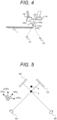
- FIG. 4 is a diagram illustrating an example of an optimization axis of a translation parameter.
- the movement axis along which the treatment couch 7 translates is an x(RL) axis, a y(SI) axis, and a z(AP) axis.
- the optimization axes of the translation parameter are an FPD 1 axis which is an imaging axis connecting the center of the FPD 5A and the X-ray tube 6A, an FPD 2 axis which is an imaging axis connecting the center of the FPD 5B and the X-ray tube 6B, and a y axis.
- the FPD 1 axis and the FPD 2 axis are different from the x axis and the z axis as in the present embodiment (in the example of FIG. 4 , arranged to be inclined by 45 degrees), when the x axis and the z axis are set as optimization axes, there is a possibility that an optimization difficult event that is difficult to optimize occurs. Meanwhile, in the present embodiment, it is possible to suppress the optimization difficult event by setting the optimization axes of the translation parameters to the FPD 1 axis, the FPD 2 axis, and the y axis without performing the optimization calculation of the two translation directions with the x axis and the z axis as the optimization axes.
- the optimization difficult event is an event in which the result of performing the optimization calculation in the one-dimensional direction affects the result of the optimization calculation in another direction, the number of iterations of the optimization calculation increases, or the optimum value cannot be reached due to the influence of the local optimal solution.
- FIGS. 5 and 6 are diagrams for explaining the optimization difficulty phenomenon in more detail.
- FIG. 5 is a diagram illustrating a relationship between an optimization axis and an imaging system (FPDs 5A and 5B and X-ray tubes 6A and 6B).
- the FPD 1 axis and the FPD 2 axis are oriented along a plane orthogonal to the y axis (a plane formed by the x axis and the z axis), and are shifted from the x axis and the z axis by 45 degrees, respectively.
- FIG. 6 is a diagram illustrating a score map image representing a distribution of matching scores as the similarity between the X-ray fluoroscopic image and the simulated-X-ray fluoroscopic image.
- the score map image is an image indicating a matching score for each relative position with respect to the position on the planned arrangement of the positioning target structure. Shading of the score map image represents a magnitude of the matching score, and the brighter the shading, the higher the matching score.
- a score map image 100 illustrated in FIG. 6(a) represents the distribution of the matching scores in the x-axis direction and the z-axis direction in a case where the optimization axis is the movement axis (x-axis, y-axis, and z-axis) of the treatment couch 7, and a score map image 101 illustrated in FIG. 6(b) represents the distribution in the FPD 1 axis direction and the FPD 2 axis direction in a case where the optimization axis is the FPD 1 axis, the FPD 2 axis, and the y-axis as in the present embodiment.
- a high score band 200 having a high matching score exists in an oblique direction. This is because the high score band 200 appears along the imaging axes (the FPD1 axis and the FPD2 axis).
- the matching score is a value corresponding to the position B in the score map image 100.
- the value of the parameter is determined such that the matching score is the highest in the one-dimensional direction along the target optimization axis. For example, when the optimization calculation in the y-axis direction and the z-axis direction is performed after the optimization calculation in the x-axis direction, the position of the positioning target structure in the score map image 100 does not immediately become the position A, but is optimized to the position of the high score band 200 existing on the x-direction side of the position B.
- the position of the positioning target structure in the score map image 100 is updated in zigzag and the values in the x direction and the z direction in the high score band 200.
- the number of iterations of the optimization calculation increases, and in some cases, the value of the parameter is locally optimized, and an appropriate value may not be reached.
- the high score band 201 exists along the optimization axis. Therefore, it is possible to suppress the zigzag update of the position of the positioning target structure in the score map image 100 as described above, and the value of the parameter can be efficiently optimized to an appropriate value.
- Step S201 the optimization calculation processing unit 25 performs one-dimensional optimization calculation for each component of the rotation component (Step S202).
- the optimization axis (rotation axis) may be the same as the movement axis (x, y, z) of the treatment couch 7, or may be the same as the optimization axis (FPD1 axis, FPD2 axis, y axis) of the translation component.
- the optimization calculation processing unit 25 determines whether or not an optimization result that is a result of the optimization calculation of the arrangement parameters satisfies a convergence condition (Step S203).
- the optimization calculation processing unit 25 determines that the optimization result satisfies the convergence condition when Formula (2) is satisfied in a case where the matching score (similarity) in the current optimization result is f ret and the matching score in the previous optimization result is f p .
- r is a constant value called a relative allowable error value, and may be determined in advance or may be settable by the user, for example.
- represents a change amount of the matching score in the current optimization result from the matching score in the previous optimization result
- )/2 represents an average value of the matching score in the current optimization result and the matching score in the previous optimization result.
- Step S203 the optimization calculation processing unit 25 determines whether or not an additional optimization calculation process is necessary (Step S204).
- the optimization calculation processing unit 25 determines whether or not additional optimization calculation is necessary, using three functions f 0 , f N , and f E expressed by Formula (3).
- f 0 f P 0
- f N f P N
- f E f 2 P N ⁇ P 0
- the function f 0 indicates the matching score at a start point P 0 before the current optimization calculation
- the function f N indicates the matching point at the optimization point P N after the current optimization calculation
- the function f E indicates a matching point at a point advanced from the optimization point P N by the same distance as the distance from the start point P 0 to the optimization point P N in an average movement direction which is the direction from the start point P 0 to the optimization point P N .
- the start point P 0 and the optimization point P N represent points (positions) in the score map image 100 of the positioning target structure.
- the optimization calculation processing unit 25 determines that there is no need to perform additional optimization calculation. f E ⁇ f 0 4 2 f 0 ⁇ 2 f N + f E f 0 ⁇ f N ⁇ ⁇ f 2 ⁇ f 0 ⁇ f E 2 ⁇ f 5
- ⁇ f is an absolute value of a value having the largest change amount among the decrease amounts of the matching score along each direction of the optimization axis in the current optimization calculation.
- Step S204 the optimization calculation processing unit 25 performs additional optimization calculation (Step S205), and returns to the processing of Step S201.
- the additional optimization calculation is a one-dimensional optimization calculation with respect to the average movement direction from the start point P 0 toward the optimization point P N .
- the optimization calculation processing unit 25 determines whether or not the number of iterations of the optimization calculation (the number of times the optimization processing including the processing of Step S201 and S202 has been executed) has reached an upper limit number specified in advance (Step S206) .
- Step S206 No
- the processing of Step S201 is executed again.
- Step S203 determines the value of the arrangement parameter to be the optimized value (Step S207), and proceeds to Step S107 of FIG. 2 .
- the particle beam therapy system is exemplified as the radiotherapy device, but the radiotherapy device is not limited to the particle beam therapy system, and may be a radiotherapy system using a non-particle beam such as an X-ray.
- the accelerator 1 includes, for example, an electron beam accelerator that outputs X-rays.
- the image acquisition unit 21 acquires the plurality of X-ray fluoroscopic images obtained by imaging the patient B along each of the plurality of imaging axes in directions different from the plurality of movement axes along which the treatment couch 7 on which the patient B is mounted translates.
- the simulated-X-ray fluoroscopic image creation unit 22 creates the plurality of simulated-X-ray fluoroscopic images obtained by projecting the three-dimensional fluoroscopic image of the patient B on each of the plurality of surfaces corresponding to each imaging axis.
- the similarity calculation unit 24 calculates the similarity between each X-ray fluoroscopic image and each simulated-X-ray fluoroscopic image.
- the optimization calculation processing unit 25 calculates the movement amount of the treatment couch 7 such that each X-ray fluoroscopic image and each simulated-X-ray fluoroscopic image coincide most in each of the plurality of translation directions along each of the plurality of optimization axes including the plurality of imaging axes and the plurality of rotation directions around the plurality of rotation axes.
- the imaging axes are substantially orthogonal to each other. Therefore, the parameter can be more appropriately optimized.
- the number of imaging axes is two. Therefore, since the optimization calculation can be performed in the minimum necessary direction, an increase in the calculation amount can be suppressed.
- the imaging axis is oriented in a direction along a plane formed by any two axes of the movement axes. Therefore, the optimization calculation can be more appropriately performed.
- the optimization calculation can be more appropriately performed.
Landscapes
- Health & Medical Sciences (AREA)
- Engineering & Computer Science (AREA)
- Biomedical Technology (AREA)
- Pathology (AREA)
- Nuclear Medicine, Radiotherapy & Molecular Imaging (AREA)
- Radiology & Medical Imaging (AREA)
- Life Sciences & Earth Sciences (AREA)
- Animal Behavior & Ethology (AREA)
- General Health & Medical Sciences (AREA)
- Public Health (AREA)
- Veterinary Medicine (AREA)
- Radiation-Therapy Devices (AREA)
Applications Claiming Priority (2)
| Application Number | Priority Date | Filing Date | Title |
|---|---|---|---|
| JP2021181771A JP2023069702A (ja) | 2021-11-08 | 2021-11-08 | 位置決め装置、放射線治療装置及び位置決め方法 |
| PCT/JP2022/030807 WO2023079811A1 (ja) | 2021-11-08 | 2022-08-12 | 位置決め装置、放射線治療装置及び位置決め方法 |
Publications (2)
| Publication Number | Publication Date |
|---|---|
| EP4431149A1 true EP4431149A1 (de) | 2024-09-18 |
| EP4431149A4 EP4431149A4 (de) | 2025-09-24 |
Family
ID=86241186
Family Applications (1)
| Application Number | Title | Priority Date | Filing Date |
|---|---|---|---|
| EP22889636.1A Pending EP4431149A4 (de) | 2021-11-08 | 2022-08-12 | Positionierungsvorrichtung, strahlentherapievorrichtung und positionierungsverfahren |
Country Status (5)
| Country | Link |
|---|---|
| US (1) | US20240366963A1 (de) |
| EP (1) | EP4431149A4 (de) |
| JP (1) | JP2023069702A (de) |
| CN (1) | CN117836035A (de) |
| WO (1) | WO2023079811A1 (de) |
Families Citing this family (2)
| Publication number | Priority date | Publication date | Assignee | Title |
|---|---|---|---|---|
| JP2024084030A (ja) * | 2022-12-12 | 2024-06-24 | 株式会社日立製作所 | ビーム輸送システムおよび方法、ビーム輸送システムを備える加速器および該加速器を有するイオン源 |
| CN119963646B (zh) * | 2025-02-28 | 2025-10-03 | 中科超安科技有限公司 | 中子照射定位参数确定方法、电子设备及存储介质 |
Family Cites Families (41)
| Publication number | Priority date | Publication date | Assignee | Title |
|---|---|---|---|---|
| DE19953177A1 (de) * | 1999-11-04 | 2001-06-21 | Brainlab Ag | Exakte Patientenpositionierung durch Vergleich von rekonstruierten und Linac-Röntgenbildern |
| DE10051370A1 (de) * | 2000-10-17 | 2002-05-02 | Brainlab Ag | Verfahren und Vorrichtung zur exakten Patientenpositionierung in der Strahlentherapie und Radiochirurgie |
| JP4088058B2 (ja) * | 2001-10-18 | 2008-05-21 | 株式会社東芝 | X線コンピュータ断層撮影装置 |
| US7522779B2 (en) * | 2004-06-30 | 2009-04-21 | Accuray, Inc. | Image enhancement method and system for fiducial-less tracking of treatment targets |
| DE102004040629B4 (de) * | 2004-08-19 | 2011-05-19 | MedCom Gesellschaft für medizinische Bildverarbeitung mbH | Einstellen einer Relativposition einer Bestrahlungseinrichtung und eines Patienten |
| US7831073B2 (en) * | 2005-06-29 | 2010-11-09 | Accuray Incorporated | Precision registration of X-ray images to cone-beam CT scan for image-guided radiation treatment |
| JP4310319B2 (ja) * | 2006-03-10 | 2009-08-05 | 三菱重工業株式会社 | 放射線治療装置制御装置および放射線照射方法 |
| US7620144B2 (en) * | 2006-06-28 | 2009-11-17 | Accuray Incorporated | Parallel stereovision geometry in image-guided radiosurgery |
| US7894649B2 (en) * | 2006-11-02 | 2011-02-22 | Accuray Incorporated | Target tracking using direct target registration |
| US7609810B2 (en) * | 2006-12-14 | 2009-10-27 | Byong Yong Yi | Treatment-speed regulated tumor-tracking |
| US7623623B2 (en) * | 2007-06-29 | 2009-11-24 | Accuray Incorporated | Non-collocated imaging and treatment in image-guided radiation treatment systems |
| US8086004B2 (en) * | 2008-01-15 | 2011-12-27 | Accuray Incorporated | Use of a single X-ray image for quality assurance of tracking |
| US8457372B2 (en) * | 2008-09-30 | 2013-06-04 | Accuray Incorporated | Subtraction of a segmented anatomical feature from an acquired image |
| JP5656170B2 (ja) * | 2009-02-26 | 2015-01-21 | 国立大学法人北海道大学 | ターゲット追跡装置および放射線治療装置 |
| WO2011061827A1 (ja) * | 2009-11-18 | 2011-05-26 | 三菱重工業株式会社 | 放射線治療装置制御方法および放射線治療装置制御装置 |
| US8804901B2 (en) * | 2010-06-08 | 2014-08-12 | Accuray Incorporated | Imaging methods for image-guided radiation treatment |
| WO2012019162A1 (en) * | 2010-08-06 | 2012-02-09 | Accuray, Inc. | Systems and methods for real-time tumor tracking during radiation treatment using ultrasound imaging |
| US8824630B2 (en) * | 2010-10-29 | 2014-09-02 | Accuray Incorporated | Method and apparatus for treating a target's partial motion range |
| JP2013099431A (ja) * | 2011-11-08 | 2013-05-23 | Natl Inst Of Radiological Sciences | 放射線治療における患者自動位置決め装置及び方法並びに患者自動位置決め用プログラム |
| JP6181459B2 (ja) * | 2013-08-05 | 2017-08-16 | 株式会社日立製作所 | 放射線治療システム |
| US9616251B2 (en) * | 2014-07-25 | 2017-04-11 | Varian Medical Systems, Inc. | Imaging based calibration systems, devices, and methods |
| JP2016116659A (ja) * | 2014-12-19 | 2016-06-30 | 株式会社東芝 | 医用画像処理装置、治療システム、医用画像処理方法、および医用画像処理プログラム |
| JP6668902B2 (ja) * | 2016-04-12 | 2020-03-18 | 株式会社島津製作所 | 位置決め装置および位置決め装置の作動方法 |
| US20180193668A1 (en) * | 2017-01-06 | 2018-07-12 | Accuray Incorporated | Partial view interfraction treatment target motion management using volumetric imaging |
| US11446520B2 (en) * | 2017-03-14 | 2022-09-20 | National Univ. Corporation Hokkaido Univ. | Radiation therapy apparatus configured to track a tracking object moving in an irradiation object |
| US11478662B2 (en) * | 2017-04-05 | 2022-10-25 | Accuray Incorporated | Sequential monoscopic tracking |
| JP6964309B2 (ja) * | 2017-08-23 | 2021-11-10 | 株式会社島津製作所 | 放射線治療用追跡装置 |
| JP7057934B2 (ja) * | 2017-12-07 | 2022-04-21 | 株式会社日立製作所 | 放射線治療システム |
| JP7553040B2 (ja) * | 2017-12-20 | 2024-09-18 | 国立研究開発法人量子科学技術研究開発機構 | 医用装置、医用装置の制御方法、およびプログラム |
| JP7140320B2 (ja) * | 2017-12-20 | 2022-09-21 | 国立研究開発法人量子科学技術研究開発機構 | 医用装置、医用装置の制御方法、およびプログラム |
| JP7116944B2 (ja) * | 2017-12-20 | 2022-08-12 | 国立研究開発法人量子科学技術研究開発機構 | 医用装置、医用装置の制御方法、およびプログラム |
| JP7298835B2 (ja) * | 2017-12-20 | 2023-06-27 | 国立研究開発法人量子科学技術研究開発機構 | 医用装置、医用装置の制御方法、およびプログラム |
| JP7178009B2 (ja) * | 2017-12-20 | 2022-11-25 | 国立研究開発法人量子科学技術研究開発機構 | 医用装置、医用装置の制御方法、およびプログラム |
| JP6996711B2 (ja) * | 2018-03-20 | 2022-01-17 | 国立研究開発法人量子科学技術研究開発機構 | 医用画像処理装置、治療システム、および医用画像処理プログラム |
| JP7093075B2 (ja) * | 2018-04-09 | 2022-06-29 | 東芝エネルギーシステムズ株式会社 | 医用画像処理装置、医用画像処理方法、およびプログラム |
| JP7311859B2 (ja) * | 2019-03-25 | 2023-07-20 | 株式会社日立製作所 | 動体追跡装置とそれを備えた放射線治療システム、プログラム、および動体の追跡方法 |
| JP7287828B2 (ja) * | 2019-04-26 | 2023-06-06 | 株式会社日立製作所 | 患者位置決めシステム、方法およびプログラム |
| JP7311109B2 (ja) * | 2019-05-14 | 2023-07-19 | 東芝エネルギーシステムズ株式会社 | 医用画像処理装置、医用画像処理プログラム、医用装置、および治療システム |
| JP7252847B2 (ja) * | 2019-07-08 | 2023-04-05 | 株式会社日立製作所 | 動体追跡装置および放射線治療システム、ならびに動体追跡装置の作動方法 |
| JP7444387B2 (ja) * | 2019-10-10 | 2024-03-06 | 東芝エネルギーシステムズ株式会社 | 医用画像処理装置、医用画像処理プログラム、医用装置、および治療システム |
| US11922656B2 (en) * | 2019-11-25 | 2024-03-05 | Accuray Incorporated | Partial deformation maps for reconstructing motion-affected treatment dose using machine learning |
-
2021
- 2021-11-08 JP JP2021181771A patent/JP2023069702A/ja active Pending
-
2022
- 2022-08-12 EP EP22889636.1A patent/EP4431149A4/de active Pending
- 2022-08-12 WO PCT/JP2022/030807 patent/WO2023079811A1/ja not_active Ceased
- 2022-08-12 US US18/689,116 patent/US20240366963A1/en active Pending
- 2022-08-12 CN CN202280057672.9A patent/CN117836035A/zh active Pending
Also Published As
| Publication number | Publication date |
|---|---|
| US20240366963A1 (en) | 2024-11-07 |
| CN117836035A (zh) | 2024-04-05 |
| EP4431149A4 (de) | 2025-09-24 |
| WO2023079811A1 (ja) | 2023-05-11 |
| JP2023069702A (ja) | 2023-05-18 |
Similar Documents
| Publication | Publication Date | Title |
|---|---|---|
| US10653891B2 (en) | Particle beam treatment system, particle beam treatment management system and method | |
| US9061143B2 (en) | Charged particle beam irradiation system and charged particle beam irradiation planning method | |
| US8792615B2 (en) | Method for identifying possible changes in the range of a planned irradiation field before the patient is irradiated with charged particles | |
| JP5197025B2 (ja) | 放射線治療システム、放射線治療支援装置及び放射線治療支援プログラム | |
| JP5197026B2 (ja) | 放射線治療システム、放射線治療支援装置及び放射線治療支援プログラム | |
| JP5238242B2 (ja) | 放射線治療用線量分布測定装置及び放射線治療用線量分布測定プログラム | |
| JP2000140137A (ja) | 放射線治療の患者位置決め方法及び装置 | |
| JP2009160307A (ja) | 放射線治療システム、放射線治療支援装置及び放射線治療支援プログラム | |
| EP4431149A1 (de) | Positionierungsvorrichtung, strahlentherapievorrichtung und positionierungsverfahren | |
| JP2016144573A (ja) | 画像処理装置および粒子線治療装置 | |
| EP4480536A1 (de) | Positionierungsvorrichtung, strahlentherapievorrichtung und positionierungsverfahren | |
| JP5121482B2 (ja) | 放射線治療用線量分布測定装置および放射線治療用線量分布測定プログラム | |
| JP7220403B2 (ja) | 粒子線治療システム、計測粒子線ct画像生成方法、およびct画像生成プログラム | |
| US20220401758A1 (en) | Patient anatomical structure change detection method, patient anatomical structure change detection device, and computer program | |
| EP3338860A1 (de) | Registrierung von teilchenstrahlradiographiedaten | |
| JP2024158687A (ja) | 位置決め装置、放射線治療装置及び位置決め方法 | |
| JP7553264B2 (ja) | 位置決め装置、放射線治療装置、位置決め方法及びコンピュータプログラム | |
| US12329989B2 (en) | Particle therapy system, irradiation control apparatus, and irradiation control method | |
| US12544594B2 (en) | Devices and methods for adaptively controlling a radiotherapy apparatus | |
| JP7563951B2 (ja) | 位置決め装置、放射線治療システム、および位置決め方法 | |
| EP4344735A1 (de) | Vorrichtungen und verfahren zur adaptiven steuerung einer strahlentherapievorrichtung | |
| JP2025081112A (ja) | 位置決め装置および位置決め装置を有する放射線治療システム、位置決め方法 | |
| JP2023023437A (ja) | 粒子線治療システム、および治療計画装置 |
Legal Events
| Date | Code | Title | Description |
|---|---|---|---|
| STAA | Information on the status of an ep patent application or granted ep patent |
Free format text: STATUS: THE INTERNATIONAL PUBLICATION HAS BEEN MADE |
|
| PUAI | Public reference made under article 153(3) epc to a published international application that has entered the european phase |
Free format text: ORIGINAL CODE: 0009012 |
|
| STAA | Information on the status of an ep patent application or granted ep patent |
Free format text: STATUS: REQUEST FOR EXAMINATION WAS MADE |
|
| 17P | Request for examination filed |
Effective date: 20240321 |
|
| AK | Designated contracting states |
Kind code of ref document: A1 Designated state(s): AL AT BE BG CH CY CZ DE DK EE ES FI FR GB GR HR HU IE IS IT LI LT LU LV MC MK MT NL NO PL PT RO RS SE SI SK SM TR |
|
| DAV | Request for validation of the european patent (deleted) | ||
| DAX | Request for extension of the european patent (deleted) | ||
| A4 | Supplementary search report drawn up and despatched |
Effective date: 20250822 |
|
| RIC1 | Information provided on ipc code assigned before grant |
Ipc: A61N 5/10 20060101AFI20250818BHEP |