EP4431200A1 - Verfahren zur herstellung eines lageraussenringes - Google Patents
Verfahren zur herstellung eines lageraussenringes Download PDFInfo
- Publication number
- EP4431200A1 EP4431200A1 EP24162968.2A EP24162968A EP4431200A1 EP 4431200 A1 EP4431200 A1 EP 4431200A1 EP 24162968 A EP24162968 A EP 24162968A EP 4431200 A1 EP4431200 A1 EP 4431200A1
- Authority
- EP
- European Patent Office
- Prior art keywords
- geometric envelope
- plate
- manufacturing
- cylindrical portions
- envelope
- Prior art date
- Legal status (The legal status is an assumption and is not a legal conclusion. Google has not performed a legal analysis and makes no representation as to the accuracy of the status listed.)
- Granted
Links
Images



Classifications
-
- B—PERFORMING OPERATIONS; TRANSPORTING
- B21—MECHANICAL METAL-WORKING WITHOUT ESSENTIALLY REMOVING MATERIAL; PUNCHING METAL
- B21K—MAKING FORGED OR PRESSED METAL PRODUCTS, e.g. HORSE-SHOES, RIVETS, BOLTS OR WHEELS
- B21K23/00—Making other articles
-
- B—PERFORMING OPERATIONS; TRANSPORTING
- B21—MECHANICAL METAL-WORKING WITHOUT ESSENTIALLY REMOVING MATERIAL; PUNCHING METAL
- B21D—WORKING OR PROCESSING OF SHEET METAL OR METAL TUBES, RODS OR PROFILES WITHOUT ESSENTIALLY REMOVING MATERIAL; PUNCHING METAL
- B21D53/00—Making other particular articles
- B21D53/10—Making other particular articles parts of bearings; sleeves; valve seats or the like
-
- F—MECHANICAL ENGINEERING; LIGHTING; HEATING; WEAPONS; BLASTING
- F16—ENGINEERING ELEMENTS AND UNITS; GENERAL MEASURES FOR PRODUCING AND MAINTAINING EFFECTIVE FUNCTIONING OF MACHINES OR INSTALLATIONS; THERMAL INSULATION IN GENERAL
- F16C—SHAFTS; FLEXIBLE SHAFTS; ELEMENTS OR CRANKSHAFT MECHANISMS; ROTARY BODIES OTHER THAN GEARING ELEMENTS; BEARINGS
- F16C35/00—Rigid support of bearing units; Housings, e.g. caps, covers
- F16C35/04—Rigid support of bearing units; Housings, e.g. caps, covers in the case of ball or roller bearings
- F16C35/06—Mounting or dismounting of ball or roller bearings; Fixing them onto shaft or in housing
- F16C35/07—Fixing them on the shaft or housing with interposition of an element
- F16C35/077—Fixing them on the shaft or housing with interposition of an element between housing and outer race ring
-
- B—PERFORMING OPERATIONS; TRANSPORTING
- B21—MECHANICAL METAL-WORKING WITHOUT ESSENTIALLY REMOVING MATERIAL; PUNCHING METAL
- B21D—WORKING OR PROCESSING OF SHEET METAL OR METAL TUBES, RODS OR PROFILES WITHOUT ESSENTIALLY REMOVING MATERIAL; PUNCHING METAL
- B21D22/00—Shaping without cutting, by stamping, spinning, or deep-drawing
- B21D22/02—Stamping using rigid devices or tools
- B21D22/022—Stamping using rigid devices or tools by heating the blank or stamping associated with heat treatment
-
- B—PERFORMING OPERATIONS; TRANSPORTING
- B21—MECHANICAL METAL-WORKING WITHOUT ESSENTIALLY REMOVING MATERIAL; PUNCHING METAL
- B21D—WORKING OR PROCESSING OF SHEET METAL OR METAL TUBES, RODS OR PROFILES WITHOUT ESSENTIALLY REMOVING MATERIAL; PUNCHING METAL
- B21D28/00—Shaping by press-cutting; Perforating
- B21D28/02—Punching blanks or articles with or without obtaining scrap; Notching
-
- B—PERFORMING OPERATIONS; TRANSPORTING
- B21—MECHANICAL METAL-WORKING WITHOUT ESSENTIALLY REMOVING MATERIAL; PUNCHING METAL
- B21D—WORKING OR PROCESSING OF SHEET METAL OR METAL TUBES, RODS OR PROFILES WITHOUT ESSENTIALLY REMOVING MATERIAL; PUNCHING METAL
- B21D28/00—Shaping by press-cutting; Perforating
- B21D28/02—Punching blanks or articles with or without obtaining scrap; Notching
- B21D28/16—Shoulder or burr prevention, e.g. fine-blanking
-
- B—PERFORMING OPERATIONS; TRANSPORTING
- B21—MECHANICAL METAL-WORKING WITHOUT ESSENTIALLY REMOVING MATERIAL; PUNCHING METAL
- B21D—WORKING OR PROCESSING OF SHEET METAL OR METAL TUBES, RODS OR PROFILES WITHOUT ESSENTIALLY REMOVING MATERIAL; PUNCHING METAL
- B21D28/00—Shaping by press-cutting; Perforating
- B21D28/24—Perforating, i.e. punching holes
-
- B—PERFORMING OPERATIONS; TRANSPORTING
- B23—MACHINE TOOLS; METAL-WORKING NOT OTHERWISE PROVIDED FOR
- B23P—METAL-WORKING NOT OTHERWISE PROVIDED FOR; COMBINED OPERATIONS; UNIVERSAL MACHINE TOOLS
- B23P15/00—Making specific metal objects by operations not covered by a single other subclass or a group in this subclass
-
- F—MECHANICAL ENGINEERING; LIGHTING; HEATING; WEAPONS; BLASTING
- F16—ENGINEERING ELEMENTS AND UNITS; GENERAL MEASURES FOR PRODUCING AND MAINTAINING EFFECTIVE FUNCTIONING OF MACHINES OR INSTALLATIONS; THERMAL INSULATION IN GENERAL
- F16C—SHAFTS; FLEXIBLE SHAFTS; ELEMENTS OR CRANKSHAFT MECHANISMS; ROTARY BODIES OTHER THAN GEARING ELEMENTS; BEARINGS
- F16C19/00—Bearings with rolling contact, for exclusively rotary movement
- F16C19/02—Bearings with rolling contact, for exclusively rotary movement with bearing balls essentially of the same size in one or more circular rows
- F16C19/04—Bearings with rolling contact, for exclusively rotary movement with bearing balls essentially of the same size in one or more circular rows for radial load mainly
- F16C19/06—Bearings with rolling contact, for exclusively rotary movement with bearing balls essentially of the same size in one or more circular rows for radial load mainly with a single row or balls
-
- F—MECHANICAL ENGINEERING; LIGHTING; HEATING; WEAPONS; BLASTING
- F16—ENGINEERING ELEMENTS AND UNITS; GENERAL MEASURES FOR PRODUCING AND MAINTAINING EFFECTIVE FUNCTIONING OF MACHINES OR INSTALLATIONS; THERMAL INSULATION IN GENERAL
- F16C—SHAFTS; FLEXIBLE SHAFTS; ELEMENTS OR CRANKSHAFT MECHANISMS; ROTARY BODIES OTHER THAN GEARING ELEMENTS; BEARINGS
- F16C33/00—Parts of bearings; Special methods for making bearings or parts thereof
- F16C33/30—Parts of ball or roller bearings
- F16C33/58—Raceways; Race rings
- F16C33/583—Details of specific parts of races
- F16C33/586—Details of specific parts of races outside the space between the races, e.g. end faces or bore of inner ring
-
- F—MECHANICAL ENGINEERING; LIGHTING; HEATING; WEAPONS; BLASTING
- F16—ENGINEERING ELEMENTS AND UNITS; GENERAL MEASURES FOR PRODUCING AND MAINTAINING EFFECTIVE FUNCTIONING OF MACHINES OR INSTALLATIONS; THERMAL INSULATION IN GENERAL
- F16C—SHAFTS; FLEXIBLE SHAFTS; ELEMENTS OR CRANKSHAFT MECHANISMS; ROTARY BODIES OTHER THAN GEARING ELEMENTS; BEARINGS
- F16C33/00—Parts of bearings; Special methods for making bearings or parts thereof
- F16C33/30—Parts of ball or roller bearings
- F16C33/58—Raceways; Race rings
- F16C33/64—Special methods of manufacture
-
- F—MECHANICAL ENGINEERING; LIGHTING; HEATING; WEAPONS; BLASTING
- F16—ENGINEERING ELEMENTS AND UNITS; GENERAL MEASURES FOR PRODUCING AND MAINTAINING EFFECTIVE FUNCTIONING OF MACHINES OR INSTALLATIONS; THERMAL INSULATION IN GENERAL
- F16C—SHAFTS; FLEXIBLE SHAFTS; ELEMENTS OR CRANKSHAFT MECHANISMS; ROTARY BODIES OTHER THAN GEARING ELEMENTS; BEARINGS
- F16C35/00—Rigid support of bearing units; Housings, e.g. caps, covers
- F16C35/04—Rigid support of bearing units; Housings, e.g. caps, covers in the case of ball or roller bearings
- F16C35/06—Mounting or dismounting of ball or roller bearings; Fixing them onto shaft or in housing
- F16C35/067—Fixing them in a housing
-
- F—MECHANICAL ENGINEERING; LIGHTING; HEATING; WEAPONS; BLASTING
- F16—ENGINEERING ELEMENTS AND UNITS; GENERAL MEASURES FOR PRODUCING AND MAINTAINING EFFECTIVE FUNCTIONING OF MACHINES OR INSTALLATIONS; THERMAL INSULATION IN GENERAL
- F16C—SHAFTS; FLEXIBLE SHAFTS; ELEMENTS OR CRANKSHAFT MECHANISMS; ROTARY BODIES OTHER THAN GEARING ELEMENTS; BEARINGS
- F16C2226/00—Joining parts; Fastening; Assembling or mounting parts
- F16C2226/50—Positive connections
- F16C2226/52—Positive connections with plastic deformation, e.g. caulking or staking
Definitions
- the invention relates to a method of manufacturing a retaining flange for an outer bearing ring, to a retaining flange obtained by this method, and to a rotation guide assembly integrating such a retaining flange.
- the invention applies more particularly to retaining flanges for retaining and guiding an outer bearing ring during its assembly inside a casing, for example a transmission or engine casing, in particular an electric motor, of a motor vehicle.
- a casing for example a transmission or engine casing, in particular an electric motor, of a motor vehicle.
- Such retaining flanges do not necessarily have a function once the transmission box is assembled.
- a method for assembling a retaining flange in a groove of an outer bearing ring, formed between a front surface of the ring having a first diameter and a rear surface of the ring having a second diameter greater than the first diameter.
- the retaining flange has a bore whose diameter is between said first and second diameters, a mounting lug which projects radially inwards relative to the diameter of the bore, as well as at least one assembly member which is radially deformable between a mounting state and a mounted state.
- this assembly must imperatively preserve sufficient functional clearance to allow movement of the bearing ring in the retaining flange.
- this type of retaining flange can be used to facilitate blind mounting of a bearing in a housing. After mounting the bearing on a shaft and the retaining flange on the outer ring of the bearing, the subassembly thus formed is introduced blindly into a housing of transmission box.
- Threaded rods or screws passing through mounting holes of a bottom plate of the housing, are screwed into tapped holes of the retaining flange, and allow the flange to be gradually brought into a final position, by indirectly exerting on the outer ring of the bearing an axial force allowing the positioning, in particular the adjustment or shrinking of this outer ring in a housing provided for this purpose in the bottom plate of the housing.
- the invention aims to remedy the drawbacks of the state of the art and to propose a method of manufacturing a retaining flange of the preceding type, in a limited number of operations, the resulting retaining flange making it possible to limit the problems described above encountered during assembly.
- the rough geometric envelope, the front geometric envelope, and the back geometric envelope are three closed surfaces.
- the flange blank has, on its part located inside the front geometric envelope, between the roughing geometric envelope and the front geometric envelope, a thickness corresponding to the difference between the initial thickness of the plate and the penetration depth of the first tool.
- the cutting of the final bore by penetration of the second tool is therefore carried out on a thickness less than the initial thickness of the plate, which considerably reduces the tearing effect at the end of cutting, and thus better controls the dimensions of the final bore.
- the resulting retaining flange has, on the periphery of the final bore, in the space between the front geometric envelope and the rear geometric envelope, a reduced thickness, corresponding to the difference between the initial thickness of the plate and the penetration depth of the first tool.
- This reduced thickness is preferably chosen to be strictly less than the width of the groove formed in the outer ring for which the retaining flange is intended.
- the portion of the retaining flange whose thickness remains equal to the initial thickness of the plate is located radially outside the front geometric envelope, and does not risk coming into contact with the outer bearing ring in the nominal position.
- the tools can be arranged on different forming stations and the metal plates conveyed from one forming station to the next by any suitable means, for example by a conveyor belt.
- Each station is equipped with a lower die on which the metal plate rests and is held at each forming step.
- the tools can be driven by any suitable means, for example by one or more mechanical or hydraulic presses.
- a single press carries, among other things, the first and second tools, which thus work synchronously on the metal plates which are conveyed from one station to the other at each press lift.
- the repelled material may be contained in a die facing the first tool.
- a preliminary step is provided in which a roughing tool penetrates along the reference axis in the penetration direction from the front face, to perforate the plate and form a roughing hole having as its outline the geometric roughing envelope surrounding the reference axis.
- the material repelled by the penetration of the first tool penetrates into the roughing hole.
- the roughing tool for perforating the plate may be a punch of any shape, for example example a circular or rectangular punch, with a section equal to the section of the geometric roughing envelope.
- the metal plate is preferably rectangular.
- the assembly notch of the front geometric envelope is perforated along the reference axis to form a hole and a plastically deformable assembly member located between the hole and the rear geometric envelope.
- the perforation is preferably carried out during the penetration step of the first tool or the penetration step of the second tool.
- the assembly member formed on the notch of the front geometric envelope is then obtained without an additional step.
- the rear geometric envelope comprises cylindrical portions centered on the reference axis, two of the cylindrical portions being located on either side of a first singularity of the rear geometric envelope, the first singularity being located radially in the extension of the holding notch, to form a tab of thickness less than the thickness of the metal plate projecting radially towards the reference axis relative to the cylindrical portions of the rear geometric envelope.
- the tabs will be formed in the material resulting from the step of pushing the material between the front geometric envelope and the rough geometric envelope.
- the first singularity comprises connection zones between the tab and the two cylindrical portions located on either side of the first singularity, the connection zones extending radially outside the cylindrical portions located on either side of the first singularity.
- the front geometric envelope comprises in all two diametrically opposed cylindrical portions, and a retaining notch and an assembly notch separating the two cylindrical portions of the front geometric envelope, the retaining notch and the assembly notch being diametrically opposed.
- the perforations are made by punching.
- the first tool is a punch with a section equal to the section of the front geometric envelope. It performs a stamping that can be done hot or cold.
- the second tool used to perforate the plate is a cylindrical punch with a section between the section of the rough geometric envelope and the section of the front geometric envelope, the punch making it possible to obtain an at least partially clean cut.
- mounting holes and holding holes are cut into the plate, radially outside the front geometric envelope of the plate, the holding holes serving to hold the plate during the manufacturing steps.
- the holding holes can be located radially outside the threaded mounting holes.
- the threaded mounting holes allow the holding flange to be fixed to the housing of the vehicle using fasteners.
- a contour of the plate is cut out, surrounding the mounting holes and located radially inside the retaining holes.
- the outline of the plate is made at the end of the flange manufacturing steps, using a cutting tool.
- the second tool produces a sharp edge at the intermediate depth and a clean cut of the final bore over a depth of at least 0.5 mm from the sharp edge in the direction of penetration.
- the clean cut is carried out over the entire thickness of the plate.
- the latter relates to a method of manufacturing a rotational guide assembly intended to be mounted inside a housing, comprising the manufacture of a retaining flange as described previously, and the mounting of the retaining flange in a groove of an outer ring of a bearing, the groove having a front bearing surface having a first diameter and a rear bearing surface having a second diameter greater than the first diameter, characterized in that the tab of the retaining flange is inserted into the groove of the outer ring of the bearing and in that the assembly member is plastically deformed to insert it radially and at least partially into the groove, with a clearance greater than 0.1 mm between the deformed assembly member and the bottom of the groove.
- the latter relates to a rotation guide assembly intended to be mounted inside a casing, obtained by the preceding manufacturing method.
- FIG. 1 On the figure 1 is illustrated the mounting of a primary or secondary shaft 2 in a casing 10 of a gearbox or engine, in particular an electric motor, of a motor vehicle, said mounting being carried out by means of a bearing 12 comprising an outer ring 14, an inner ring 16 and rolling bodies 18 arranged between said rings 14 and 16 to allow their relative rotation.
- a bearing 12 comprising an outer ring 14, an inner ring 16 and rolling bodies 18 arranged between said rings 14 and 16 to allow their relative rotation.
- the inner ring 16 is rotating and shrunk on the shaft 2
- the outer ring 14 is fixed and shrunk or mounted adjusted in a housing bottom 101 of a bore 3 of the casing 10.
- the rolling bodies 18 are here balls, but could also be, for example, conical or cylindrical rollers.
- the outer ring 14 has a groove 22 formed of a front bearing surface 17 of a first diameter and a rear bearing surface 19 of a second diameter strictly greater than the first diameter.
- the front bearing surface 17 forms a front flank 4 of the groove 22 and the rear bearing surface 19 forms a rear flank 5 of the groove 22, opposite the front flank 4.
- On the outer ring 14 is mounted a retaining flange 20 comprising a front face 201 facing away from the casing 10, and a rear face 202 facing the casing 10 and the rear flank 5 of the groove 22.
- the retaining flange 20 is assembled in the groove 22 of the bearing 12, by a method that will be described later.
- the assembly consisting of the retaining flange 20 and the bearing 12 is then shrink-fitted onto an axial end of the shaft 2.
- the subassembly consisting of the shaft 2, the bearing 12 and the retaining flange 20 is then positioned blindly axially at the entrance of the bore 3 of the casing 10.
- screws 6 are used, which pass through the casing 10 and engage in mounting holes 28, which may be, for example, threaded holes.
- the retaining flange 20 has, between the front face 201 and the rear face 202, a relatively large thickness, preferably greater than the width of the groove 22 between the front flank 4 and the rear flank 5, this to give the retaining flange 20 a high stiffness, sufficient to transmit the assembly forces and support the forces transmitted by the shaft 2.
- a bore 25 having as its outline a geometric envelope 41 which will be called the front geometric envelope, centered on a reference axis 1 of the flange 20.
- a bore 24 called the final bore having as its outline a geometric envelope 43 which will be called the rear geometric envelope, centered on the reference axis 1 of the flange 20.
- the front geometric envelope 41 is composed of two cylindrical portions 251, 252 diametrically opposed and separated by a holding notch 29 and an assembly notch 31 preferably diametrically opposed.
- the holding notch 29 has a U shape in axial projection (see also the Figures 4b And 5b ), the width of the notch, measured in the radial direction, being less than its length, measured in the orthoradial direction.
- the assembly notch 31 also has, still in axial projection, a U shape, the width of the assembly notch 31 being less than its length.
- the holding notch 29 and the assembly notch 31 project radially outwards from the holding flange 20.
- the rear geometric envelope 43 is composed of two cylindrical portions 241, 242 diametrically opposed and separated by two singularities 11 and 13, the rear geometric envelope 43 being of smaller dimensions than the front geometric envelope 41.
- the first singularity 11 is located radially in the extension of the holding notch 29 and the second singularity 13 is located radially in the extension of the assembly notch 31.
- Connection zones 9 connect the cylindrical portions 241, 242 and the first singularity 11 and connection zones 15 connect the cylindrical portions 241, 242 and the second singularity 15.
- connection zones 9 extend radially outside the cylindrical portions 241, 242 of the rear geometric envelope 43 and axially over the thickness of the rear geometric envelope 43 or over any the thickness of the retaining flange 20 ; and the connection zones 15 extend radially outside the cylindrical portions 241, 242 of the rear geometric envelope 43 and axially over the thickness of the rear geometric envelope 43 or over the entire thickness of the retaining flange 20.
- the connection zones 9 and 15 are in the form of material recesses, for example rounded recesses oriented radially towards the outside of the flange 20.
- a tab 33 In the axial extension of the retaining notch 29 and up to the rear face 202 of the retaining flange 20 is formed a tab 33, and in the axial extension of the assembly notch 31 and up to the rear face 202 of the retaining flange 20 is pierced a hole 310, preferably oblong, of dimensions smaller than those of the second notch 31.
- a boss 27 At the center of the edge of the oblong hole 310 which borders the rear geometric envelope 43, there is preferably a boss 27 oriented radially towards the outside of the retaining flange 20.
- the thickness of material located between the rear geometric envelope 43 of the flange 20 and the hole 310 of the assembly notch 31 constitutes an assembly member 26, plastically deformable between a mounting state, as shown in the Figures 2a And 2b , And a mounted state, in which the assembly member 26 moves radially towards the inside of the retaining flange 20.
- the outer contour of the retaining flange 20 is formed of cylindrical portions connected by fixing lugs 23 oriented radially towards the outside of the retaining flange 20.
- the mounting holes 28 are located in the center of the fixing lugs 23.
- the front geometric envelope 41 can be formed of more than two cylindrical portions separated by more than two notches, so that the retaining flange 20 can comprise more than one assembly member 26, and/or more than one tab 33.
- a method of assembling the retaining flange 20 around the outer ring 14 is described below.
- the retaining notch 29 is inserted into the groove 22 of the outer ring 14 by the relative inclination of the final bore 24 relative to the front bearing surface 17 of the groove 22 of the outer ring 14, in order to allow the tab 33 to pass axially beyond said front bearing surface 17.
- the assembly method provides for radially deforming at least one assembly member 26 from the mounting state to the mounted state, in order to arrange the assembly member 26 at least partly in the groove 22, in order to ensure the assembly of the retaining flange 20 by interference between the groove 22, the tab 33 and the assembly member 26.
- Figures 3a and 3b illustrate an optional preliminary step of the method of manufacturing the holding flange 20.
- a metal plate 37 is placed on a lower die of a mechanical or hydraulic press and is immobilized, using fixing means inserted into holding holes 21 drilled on the contour of the plate 37.
- a roughing punch 38 fixed on a tool holder, moves along its reference axis 1 and in a direction of penetration A, and perforates the metal plate 37 until reaching the bottom of the lower die to form the geometric roughing envelope 39.
- the roughing punch 38 has as its external shape a geometric roughing envelope 39 that is cylindrical and of a diameter smaller than the dimensions of the front geometric envelope 41.
- the geometric roughing envelope 39 is of any shape and dimensions, for example formed of two diametrically opposite cylindrical portions separated by two diametrically opposite notches.
- the metal plate 37 is of known thickness, the thickness being greater than or equal to 3 mm and less than or equal to 6 mm.
- the holding holes 21 are drilled at the same time as the geometric roughing envelope 39.
- a first punch 40 fixed on a first tool holder, moves along the reference axis 1 and along the penetration direction A, and stamps the metal plate 37 to form a material recess having the outline of the front geometric envelope 41.
- Figure 4a represents the first punch 40 partially stamping the plate 37 obtained after the step of the figure 3b on an intermediate depth less than the thickness of the plate 37. More precisely, the intermediate depth is between 1 mm and 3 mm, or between one third of the total thickness of the plate 37 and two thirds of the total thickness of the plate 37.
- the first punch 40 has the front geometric envelope 41 as its external shape.
- the cylindrical portions 251, 252 of the front geometric envelope 41 are located radially outside the rough geometric envelope 39, the radial distance being greater than 1 mm, and preferably greater than 3 mm, and less than 10 mm, preferably less than 7 mm.
- the material contained in the assembly notch 31 of the plate 37 is drilled or punched to form the oblong hole 310 and the assembly member 26.
- the mounting holes 28 are drilled or punched in the plate 37, radially at a distance from the front geometric envelope 41.
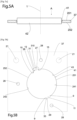
- a second punch 42 fixed on a second tool holder, moves along the reference axis 1, and perforates the metal plate 37 to form the rear geometric envelope 43.
- the second punch 42 makes a clean cut on at least part of the thickness of the plate 37, in particular on at least 0.5 mm of thickness from the face 203 and along the direction of penetration A.
- Figure 5a illustrates the second punch 42 perforating the plate 37 obtained after the step of the Figure 4a , along the reference axis 1 and in the direction of penetration A.
- the second punch 42 has the rear geometric envelope 43 as its external shape.
- the cylindrical portions 251, 252 of the front geometric envelope 41 are located radially outside the rear geometric envelope 43, at a radial distance which is greater than 0.1 mm, and preferably greater than 0.5 mm, and less than 1.0 mm, preferably less than 0.7 mm.
- a radial distance which is greater than 0.1 mm, and preferably greater than 0.5 mm, and less than 1.0 mm, preferably less than 0.7 mm.
- an outer contour of the plate is formed, the contour taking the form of cylindrical portions separated by radially outwardly oriented fixing lugs 23.
- the contour is located generally radially inside the holding holes 21 used to hold the plate 37 on the lower dies and radially outside the mounting holes 28.
- the metal plate 37 is placed on a hollow lower die 44 having a cavity for collecting material, the cavity having a depth greater than the axial distance between the intermediate thickness of the metal plate 37 and the rear face 202 of the metal plate 37.
- the hollow lower die has as its outline the geometric roughing envelope 39.
- the first punch 40 fixed on a first tool holder, moves along the reference axis 1, and stamps the plate 37 to the intermediate depth by moving the material located inside the front geometric envelope 41 into the cavity of the hollow lower die in order to form a material recess on the intermediate thickness of the plate, the recess having as its outline the front geometric envelope 41, and a volume of material pushed from the intermediate thickness of the plate 37 into the cavity of the hollow lower die, the volume of material having as its outline the rough geometric envelope 39.
- the second punch 42 having as its outline the rear geometric envelope 43, moves along the reference axis 1, and perforates the metal plate 37 to form the rear geometric envelope 43 of the metal plate 37 as shown in the Figure 5b .
- the three punches 38, 40, 42 are located on three tool holders belonging to three different presses.
Landscapes
- Engineering & Computer Science (AREA)
- Mechanical Engineering (AREA)
- General Engineering & Computer Science (AREA)
- Manufacturing & Machinery (AREA)
- Physics & Mathematics (AREA)
- Thermal Sciences (AREA)
- Forging (AREA)
- Punching Or Piercing (AREA)
- Mounting Of Bearings Or Others (AREA)
Applications Claiming Priority (1)
| Application Number | Priority Date | Filing Date | Title |
|---|---|---|---|
| FR2302522A FR3146609B1 (fr) | 2023-03-17 | 2023-03-17 | Procede de fabrication d’un flasque de maintien d’une bague exterieure d’un roulement |
Publications (2)
| Publication Number | Publication Date |
|---|---|
| EP4431200A1 true EP4431200A1 (de) | 2024-09-18 |
| EP4431200B1 EP4431200B1 (de) | 2026-05-06 |
Family
ID=86469290
Family Applications (1)
| Application Number | Title | Priority Date | Filing Date |
|---|---|---|---|
| EP24162968.2A Active EP4431200B1 (de) | 2023-03-17 | 2024-03-12 | Verfahren zur herstellung einer halterungsplatte eines lageraussenringes |
Country Status (5)
| Country | Link |
|---|---|
| US (1) | US12157161B2 (de) |
| EP (1) | EP4431200B1 (de) |
| JP (1) | JP2024150402A (de) |
| CN (1) | CN118664255A (de) |
| FR (1) | FR3146609B1 (de) |
Citations (2)
| Publication number | Priority date | Publication date | Assignee | Title |
|---|---|---|---|---|
| DE202014105640U1 (de) * | 2013-11-22 | 2014-12-05 | Nsk Ltd. | Lagervorrichtung |
| FR3032500A1 (fr) | 2015-02-11 | 2016-08-12 | Ntn-Snr Roulements | Procede d'assemblage d'une bride de fixation autour d'une bague exterieure d'un roulement |
Family Cites Families (8)
| Publication number | Priority date | Publication date | Assignee | Title |
|---|---|---|---|---|
| US3806214A (en) * | 1972-06-26 | 1974-04-23 | Timken Co | Bearing assembly having a unitized hub |
| US5237748A (en) * | 1991-12-16 | 1993-08-24 | Mcgill Manufacturing Company, Inc. | Method of making a bearing assembly |
| EP2746605B1 (de) * | 2007-07-04 | 2015-09-23 | NSK Ltd. | Montageverfahren für Lagereinheit |
| DE102009004653B4 (de) * | 2008-08-09 | 2024-03-14 | Ab Skf | Verfahren zur Herstellung einer Lageranordnung und Lageranordnung |
| EP2423524B1 (de) * | 2009-04-20 | 2018-04-18 | NSK Ltd. | Druckrollenlager und verfahren zur herstellung eines laufrings dafür |
| DE102012223449B4 (de) * | 2012-12-17 | 2019-04-25 | Aktiebolaget Skf | Wälzlageranordnung und Verfahren zum Herstellen einer Wälzlageranordnung |
| US10060472B2 (en) * | 2014-06-13 | 2018-08-28 | Nsk Ltd. | Bearing device and method for manufacturing bearing device |
| CN108662028A (zh) * | 2018-07-26 | 2018-10-16 | 内蒙古野田铁牛农业装备有限公司 | 一种新型轴承座 |
-
2023
- 2023-03-17 FR FR2302522A patent/FR3146609B1/fr active Active
-
2024
- 2024-03-11 JP JP2024037271A patent/JP2024150402A/ja active Pending
- 2024-03-12 EP EP24162968.2A patent/EP4431200B1/de active Active
- 2024-03-13 US US18/603,336 patent/US12157161B2/en active Active
- 2024-03-18 CN CN202410304292.1A patent/CN118664255A/zh active Pending
Patent Citations (3)
| Publication number | Priority date | Publication date | Assignee | Title |
|---|---|---|---|---|
| DE202014105640U1 (de) * | 2013-11-22 | 2014-12-05 | Nsk Ltd. | Lagervorrichtung |
| FR3032500A1 (fr) | 2015-02-11 | 2016-08-12 | Ntn-Snr Roulements | Procede d'assemblage d'une bride de fixation autour d'une bague exterieure d'un roulement |
| EP3056750A1 (de) * | 2015-02-11 | 2016-08-17 | NTN-SNR Roulements | Montageverfahren eines befestigungsflansches um einen aussenring eines lagers |
Also Published As
| Publication number | Publication date |
|---|---|
| US20240307949A1 (en) | 2024-09-19 |
| EP4431200B1 (de) | 2026-05-06 |
| JP2024150402A (ja) | 2024-10-23 |
| US12157161B2 (en) | 2024-12-03 |
| FR3146609B1 (fr) | 2025-03-14 |
| CN118664255A (zh) | 2024-09-20 |
| FR3146609A1 (fr) | 2024-09-20 |
Similar Documents
| Publication | Publication Date | Title |
|---|---|---|
| EP2864067B1 (de) | Rohrkerbungsverfahren und zugehörige kerbungsmaschine | |
| FR2640010A1 (fr) | Agencement pour la fixation d'une bague de roulement de grande durete dans la surface d'alesage de plus faible durete d'un logement ou sur la surface laterale de plus faible durete d'un arbre ou d'un organe analogue | |
| FR2661227A1 (fr) | Procede de realisation d'un arbre, en particulier d'un arbre de cardan, forme d'un assemblage d'un tube de matiere synthetique armee de fibres et d'un element de raccordement en materiau rigide. | |
| EP1436530B1 (de) | Differential und verfahren zur montage des diferentials | |
| EP2004988B1 (de) | Kolben für eine hydraulische radialkolbenmaschine und herstellungsverfahren dafür | |
| EP0095961B1 (de) | Verfahren zur Herstellung eines hydrodynamischen Lagers | |
| EP3625879B1 (de) | Elektrische maschine mit gerändelter rotorwelle und verfahren zur herstellung solch einer maschine | |
| EP0014107B1 (de) | Verfahren zur Herstellung einer zylindrischen Büchse mit inneren Nuten, die mindestens an einem ihrer Enden geschlossen sind und hergestellte Büchse | |
| FR2608078A1 (fr) | Procede pour fabriquer une denture helicoidale interieure | |
| FR2477460A1 (fr) | Dispositif de fixation de lames de couteaux pour arbres porte-lames ou tetes porte-lames | |
| EP4431200B1 (de) | Verfahren zur herstellung einer halterungsplatte eines lageraussenringes | |
| FR2899650A1 (fr) | Piston pour un moteur hydraulique a pistons radiaux et son procede de fabrication | |
| BE898298A (fr) | Procédé et dispositif pour la fabrication d'un tuyau pourvu de rangées de perforations, dans un dispositif d'estampage. | |
| EP0310726B1 (de) | Verfahren zum Herstellen konischer Metalldosen und Werkzeug zur Durchführung des Verfahrens | |
| FR2655576A1 (fr) | Procede et dispositif d'emboutissage de recipients de forme tronconique, et repipient ainsi embouti. | |
| FR2721769A1 (fr) | Procédé de sertissage de conducteur dans des encoches ouvertes d'un induit de machine électrique tournante et machine électrique, notamment un démarreur de véhicule automobile, comportant un induit selon le procédé. | |
| FR3028171A1 (fr) | Alesoir et procede de fabrication d'un tel alesoir | |
| FR3020424A1 (fr) | Procede de montage de corps roulants cylindriques a l'interieur d'un organe exterieur creux, sous-ensemble et palier a roulement obtenus par ce procede | |
| FR3092632A1 (fr) | Roulement comportant un flasque serti dans une des bagues du roulement ET SON PROCéDé DE FABRICATION | |
| FR2846806A1 (fr) | Procede de fabrication de conducteurs electriques en forme d'epingles en u, dispositif pour la mise en oeuvre de ce procede et conducteurs ainsi obtenus | |
| FR3095487A1 (fr) | Mécanisme de vis a rouleaux satellites | |
| EP0605332B1 (de) | Verfahren zum Herstellen von drehbaren Teilen, insbesondere von mehrrilligen Keilriemenscheiben | |
| EP4474543A1 (de) | Ausgangshebel mit nachlaufrollen eines exzenterantriebs und verfahren zu seiner herstellung | |
| FR2761913A1 (fr) | Procede de fabrication de bagues de roulement et dispositf d'outil correspondant | |
| FR2462047A1 (fr) | Petit moteur electrique, en particulier moteur pour essuie-glace |
Legal Events
| Date | Code | Title | Description |
|---|---|---|---|
| PUAI | Public reference made under article 153(3) epc to a published international application that has entered the european phase |
Free format text: ORIGINAL CODE: 0009012 |
|
| STAA | Information on the status of an ep patent application or granted ep patent |
Free format text: STATUS: REQUEST FOR EXAMINATION WAS MADE |
|
| 17P | Request for examination filed |
Effective date: 20240314 |
|
| AK | Designated contracting states |
Kind code of ref document: A1 Designated state(s): AL AT BE BG CH CY CZ DE DK EE ES FI FR GB GR HR HU IE IS IT LI LT LU LV MC ME MK MT NL NO PL PT RO RS SE SI SK SM TR |
|
| STAA | Information on the status of an ep patent application or granted ep patent |
Free format text: STATUS: EXAMINATION IS IN PROGRESS |
|
| 17Q | First examination report despatched |
Effective date: 20250321 |
|
| GRAP | Despatch of communication of intention to grant a patent |
Free format text: ORIGINAL CODE: EPIDOSNIGR1 |
|
| STAA | Information on the status of an ep patent application or granted ep patent |
Free format text: STATUS: GRANT OF PATENT IS INTENDED |
|
| INTG | Intention to grant announced |
Effective date: 20251201 |
|
| P01 | Opt-out of the competence of the unified patent court (upc) registered |
Free format text: CASE NUMBER: UPC_APP_0018396_4431200/2025 Effective date: 20251219 |
|
| GRAS | Grant fee paid |
Free format text: ORIGINAL CODE: EPIDOSNIGR3 |
|
| GRAA | (expected) grant |
Free format text: ORIGINAL CODE: 0009210 |
|
| STAA | Information on the status of an ep patent application or granted ep patent |
Free format text: STATUS: THE PATENT HAS BEEN GRANTED |