EP4431209A1 - Dispositif et procédé d'usinage de pièces sur un tour multibroches - Google Patents
Dispositif et procédé d'usinage de pièces sur un tour multibroches Download PDFInfo
- Publication number
- EP4431209A1 EP4431209A1 EP23161971.9A EP23161971A EP4431209A1 EP 4431209 A1 EP4431209 A1 EP 4431209A1 EP 23161971 A EP23161971 A EP 23161971A EP 4431209 A1 EP4431209 A1 EP 4431209A1
- Authority
- EP
- European Patent Office
- Prior art keywords
- workpiece
- turning
- whirling
- tool
- spindle
- Prior art date
- Legal status (The legal status is an assumption and is not a legal conclusion. Google has not performed a legal analysis and makes no representation as to the accuracy of the status listed.)
- Pending
Links
Images


Classifications
-
- B—PERFORMING OPERATIONS; TRANSPORTING
- B23—MACHINE TOOLS; METAL-WORKING NOT OTHERWISE PROVIDED FOR
- B23G—THREAD CUTTING; WORKING OF SCREWS, BOLT HEADS, OR NUTS, IN CONJUNCTION THEREWITH
- B23G1/00—Thread cutting; Automatic machines specially designed therefor
- B23G1/32—Thread cutting; Automatic machines specially designed therefor by milling
- B23G1/34—Thread cutting; Automatic machines specially designed therefor by milling with a cutting bit moving in a closed path arranged eccentrically with respect to the axis of the rotating workpieces
-
- B—PERFORMING OPERATIONS; TRANSPORTING
- B23—MACHINE TOOLS; METAL-WORKING NOT OTHERWISE PROVIDED FOR
- B23B—TURNING; BORING
- B23B3/00—General-purpose turning-machines or devices, e.g. centre lathes with feed rod and lead screw; Sets of turning-machines
- B23B3/06—Turning-machines or devices characterised only by the special arrangement of constructional units
- B23B3/065—Arrangements for performing other machining operations, e.g. milling, drilling
-
- B—PERFORMING OPERATIONS; TRANSPORTING
- B23—MACHINE TOOLS; METAL-WORKING NOT OTHERWISE PROVIDED FOR
- B23B—TURNING; BORING
- B23B9/00—Automatic or semi-automatic turning-machines with a plurality of working-spindles, e.g. automatic multiple-spindle machines with spindles arranged in a drum carrier able to be moved into predetermined positions; Equipment therefor
- B23B9/08—Automatic or semi-automatic machines for turning of workpieces
-
- B—PERFORMING OPERATIONS; TRANSPORTING
- B23—MACHINE TOOLS; METAL-WORKING NOT OTHERWISE PROVIDED FOR
- B23B—TURNING; BORING
- B23B2220/00—Details of turning, boring or drilling processes
- B23B2220/52—Whirling
-
- B—PERFORMING OPERATIONS; TRANSPORTING
- B23—MACHINE TOOLS; METAL-WORKING NOT OTHERWISE PROVIDED FOR
- B23B—TURNING; BORING
- B23B2250/00—Compensating adverse effects during turning, boring or drilling
- B23B2250/12—Cooling and lubrication
-
- B—PERFORMING OPERATIONS; TRANSPORTING
- B23—MACHINE TOOLS; METAL-WORKING NOT OTHERWISE PROVIDED FOR
- B23B—TURNING; BORING
- B23B2260/00—Details of constructional elements
- B23B2260/008—Bearings
- B23B2260/0082—Sliding contact bearings
-
- B—PERFORMING OPERATIONS; TRANSPORTING
- B23—MACHINE TOOLS; METAL-WORKING NOT OTHERWISE PROVIDED FOR
- B23B—TURNING; BORING
- B23B2260/00—Details of constructional elements
- B23B2260/026—Bushings, e.g. adapter sleeves
-
- B—PERFORMING OPERATIONS; TRANSPORTING
- B23—MACHINE TOOLS; METAL-WORKING NOT OTHERWISE PROVIDED FOR
- B23C—MILLING
- B23C2220/00—Details of milling processes
- B23C2220/68—Whirling
-
- B—PERFORMING OPERATIONS; TRANSPORTING
- B23—MACHINE TOOLS; METAL-WORKING NOT OTHERWISE PROVIDED FOR
- B23G—THREAD CUTTING; WORKING OF SCREWS, BOLT HEADS, OR NUTS, IN CONJUNCTION THEREWITH
- B23G2240/00—Details of equipment for threading other than threading tools, details of the threading process
- B23G2240/60—Thread whirling, i.e. production of a thread by means of an annular tool rotating about an axis not coincident with the axis of the thread being produced
Definitions
- the invention relates to a device and a method for machining workpieces, as well as a tool carrier and a multi-spindle lathe according to the preambles of claims 1, 8, 10 and 12.
- a lathe is a machine tool used to machine a workpiece. Lathes are classified according to the type of machine bed, the position of the spindle, or the number of spindles.
- the workpiece usually performs a rotary movement, with the turning processes differing according to the type of surface to be created (round turning, facing, thread turning, grooving, profile turning, form turning).
- automatic lathes For the production of simple parts in large quantities, such as nuts or screws, automatic lathes (single or multi-spindle lathes) are used, which have one or more controlled slides and/or turrets equipped with tools.
- a multi-spindle lathe the workpiece spindles are rotated in cycles to individual processing stations, where the workpiece is processed step by step.
- the main advantage of a multi-spindle lathe is that it can be used to carry out several production steps in parallel.
- the company INDEX-Werke GmbH & Co. KG Hahn & Tessky offers a CNC multi-spindle lathe called MS22-8 with eight rotating workpiece spindles, two swivel synchronous spindles and up to a maximum of 16 tool carriers, which can be configured in the XY and Z directions.
- the workpiece spindles can handle workpieces with a maximum Bar diameter of 22 mm.
- Stationary and rotating tools can be arranged on the tool carrier, with which, for example, off-center drilling and thread cutting, drilling (angled and cross drilling), contour milling or polygon turning is possible.
- short lathe short lathe
- long lathe long lathe
- a short lathe the workpiece cannot be moved in the axial direction relative to the tools.
- the tool carries out the axial movement.
- a relative movement takes place between the workpiece and the tool, whereby the workpiece is pushed into the respective spindle using a loading system and is clamped using a collet and guided in a guide bush (steady rest).
- Short turning machines have only been able to machine workpieces with a relatively small length in relation to diameter.
- Short turning machines and multi-spindle machines have not been suitable for long and narrow turned parts, as the unfavourable ratio of length to diameter meant that stable or precise machining was not possible, particularly in the area of the workpiece tip.
- the EN 10 2017 121 295 A1 discloses a multi-spindle lathe with a rotatably mounted spindle drum with workpiece spindles, wherein the workpieces can be positioned relative to stationary spindle stations by rotating the spindle drum.
- each workpiece spindle is assigned a workpiece guide bush for guiding a material rod held in the workpiece spindle, which is arranged to be movable relative to the respective workpiece spindle in a direction parallel to the workpiece spindle axis.
- a tool holder for a long-turning lathe wherein on a tool slide a housing with a rotating driven shaft, which drives various tools, such as a device for thread whirling or a milling device, via driver elements.
- various tools such as a device for thread whirling or a milling device, via driver elements.
- the present embodiment is only suitable for a long-turning machine and not for a multi-spindle automatic lathe.
- the disadvantage of the known multi-spindle lathes is that long workpieces with a length of three times the diameter cannot be machined without the workpiece oscillating or vibrating during machining.
- Another disadvantage of the known multi-spindle lathes arises when machining a long workpiece, for example when producing a screw, where at least three machining steps (turning, milling, whirling) must be carried out. Since not every slide of the multi-spindle lathe has a Y-axis, it is not possible to carry out deburring and turning at the same spindle station. Machining with a turning tool must therefore be carried out on another slide, which means that the multi-spindle lathe is not used optimally.
- An essential feature of the invention is that at least one whirling-turning-milling unit is arranged on a first tool slide and at least one guide bush carrier with at least one guide bush is arranged on the second tool slide and that the guide bush carrier guides the workpiece during machining with the whirling-turning-milling unit.
- the embodiment according to the invention offers the advantage that long workpieces can now also be machined with a multi-spindle lathe because during the machining process the workpiece is guided and stabilized by the guide bush carrier and the associated guide bush.
- the guide bush carrier is preferably arranged on the adjacent carriage of the whirling-turning-milling unit and holds or guides the workpiece to be machined between the workpiece spindle and the tool. This guides or holds the workpiece in the space between the workpiece spindle and the tool.
- the guide bush carrier is therefore an additional component which guides and stabilizes the workpiece during machining from an adjacent tool carriage.
- the multi-spindle lathe has several tool carriers with movable tool slides. Two tool carriers are assigned to each workpiece spindle and form a spindle position. This means that two tool slides are assigned to each spindle station.
- the first tool slide and the second tool slide are preferably arranged in a V shape, with the intersection point oriented towards the center of the workpiece spindle.
- the whirling-turning-milling unit is arranged on the first slide and the guide bush carrier with the guide bush is arranged on the second slide.
- first and second tool slide is used only as an example. These are two adjacent tool slides. These tool slides can be in any spindle position. In the embodiment according to the invention, any tool slide can be used. Some tools do not require any movement in the Y axis, so standardized tool slides can also be used.
- the whirling-turning-milling unit preferably comprises a housing which is arranged on a tool carriage.
- the housing is U-shaped and has two protruding legs.
- a first tool which is designed as a whirling unit, for example, is arranged on the first leg.
- a second tool is arranged on the second leg. which is designed, for example, as a milling unit.
- a rotating unit is arranged on the second leg.
- the whirling-turning-milling unit combines three different tools in one housing and on one tool carriage.
- the shape of the whirling-turning-milling unit is designed in such a way that no collisions occur between the individual tools.
- the tool can be designed as a rotary-driven or a non-rotating tool, such as a whirling unit, a turning unit or a milling unit.
- the whirling-turning-milling unit is arranged on a tool slide of the multi-spindle lathe, which moves in the X, Y and Z axes.
- the 3-axis movement makes it possible to position the individual tools of the whirling-turning-milling unit specifically in relation to the workpiece, which is arranged in one of the workpiece spindles during machining.
- a first driven tool is located on the first leg and a second driven tool is located on the second leg of the housing of the whirling-turning-milling unit.
- the tools are driven via a gear device and a drive motor, which is arranged, for example, in the base of the tool carriage.
- the drive motor is flanged directly to the whirling-turning-milling unit and is controlled by the multi-spindle lathe.
- the transmission device is used to transmit forces of any kind.
- the transmission device is designed, for example, as a gear transmission, toothed belt transmission, chain transmission and/or belt transmission.
- the housing of the whirling-turning-milling unit has a first leg, a web-like connecting body in between and a second leg, with all components having recesses and holes to accommodate the gear devices.
- the individual tools are coupled to the gear device, with a power transmission between the first and the second leg preferably via a rotatable shaft which is arranged in the connecting body.
- the guide bush carrier comprises a carrier body with a recess for receiving a guide bush.
- a guide bush is understood to be a type of bearing that guides the workpiece.
- the guide bush is preferably designed as a hollow cylinder made of a special material, with a defined inner and outer diameter.
- the guide bush is, for example, a linear plain bearing, which offers the workpiece a type of sliding guide.
- the guide bush is stationary, driven by the workpiece spindle or has its own motor, which actively drives the bush during machining.
- the guide sleeve is replaceable, whereby the diameter of the sleeve corresponds approximately to the diameter of the workpiece to be machined.
- the guide bush carrier has an external pressure supply (pump or gas pressure vessel) which continuously presses a liquid lubricant at a constant pressure via inlet channels into the guide bush, thereby creating a thin lubricating film between the guide sleeve and the workpiece.
- an external pressure supply pump or gas pressure vessel
- the multi-spindle lathe comprises a machine frame on which a spindle drum is arranged so as to be rotatably driven around a spindle drum axis.
- the spindle drum preferably has eight rotatably driven workpiece spindles which are evenly distributed around the circumference of the spindle drum.
- the workpiece to be machined is held in the workpiece spindle by a collet.
- By rotating the spindle drum the workpiece spindles are rotated relative to associated tool carriers.
- the tool carriers are arranged stationary on the machine frame. On the tool carriers there are tool slides with tools which can be moved relative to the workpieces.
- the tool carriers with the tool slides are preferably arranged in pairs, with a tool spindle two tool carriers, ie a pair of slides, are assigned to each spindle position.
- a spindle position therefore comprises a tool spindle and a pair of slides, which are arranged in a V shape. With eight tool spindles, there are therefore eight spindle positions with 16 slides.
- the tool slide is moved using a slide drive.
- the drive motor is preferably located in the tool carrier base and drives a spindle drive, for example.
- the tool slide allows the held tool to be moved in the X direction, transverse to the respective axis of the workpiece spindle, as well as in the Z direction, parallel to the respective axis of the workpiece spindle. Some slides can optionally be moved in the Y axis.
- the multi-spindle lathe has at least one swivel synchronous spindle with which the rear side of the workpiece is machined.
- the multi-spindle lathe has at least two whirling-turning-milling units which are arranged in two spindle positions.
- the two spindle positions are synchronized in such a way that no collision occurs between the two adjacent whirling-turning-milling units.
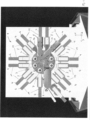
- a machine tool which is designed as a multi-spindle lathe 1.
- the multi-spindle lathe 1 has a machine bed with a rotatably mounted spindle drum 2 and workpiece spindles 3 which are driven rotatably relative to the spindle drum 2.
- the workpieces 3 to be machined are arranged in the workpiece spindles 3.
- the spindle drum 2 is rotated to the individual spindle positions and machined there with various tools 9 which are arranged on tool slides 5.
- the multi-spindle lathe 1 has eight rotating workpiece spindles 3, with each workpiece spindle 3 being assigned two tool slides 5.
- the slide pairs 11 are each arranged in a V-shape to the center of the respective tool spindle 3 and result in a so-called spindle station 19.
- spindle station 19 there are thus A total of eight spindle stations 19, each of which is marked with a number.
- Each tool slide 5 can be moved in the Z-axis, whereby the slide 5 is spaced from the spindle drum 2 by a stroke of, for example, 100 mm. Furthermore, each tool slide 5 can be moved in the X-axis, whereby the tool slide 5 can be moved relative to the workpiece spindle 3. A movement in the X-axis is necessary in order to move the novel whirling-turning-milling unit 8, which is arranged on the tool slide 5. The movement in the X-axis brings the various tools 9 of the whirling-turning-milling unit 8 into engagement with the clamped workpiece 7 in the workpiece spindle 3.
- the tool slides 5 on the spindle stations 3.1, 4.1, 5.1 and 6.1 preferably have a drive in the Y axis, whereby the whirling-turning-milling unit 8 can be pivoted in height. This is always useful when several tools 9 have to be corrected in the Y direction or when the machining requires a Y axis.
- both tool slides 5 of a slide pair 11 are used for machining on a workpiece spindle 3.
- a guide bush carrier 12 is arranged on a tool slide 5.
- the guide bush carrier 12 accommodates a separate guide bush 13, whereby the guide bush 13 is adapted to the diameter of the workpiece 7 to be machined.
- the guide bush 13 is suitable for holding a 5 mm workpiece.
- the guide bush 13 is supplied with a coolant, whereby a hydrostatic guidance of the workpiece 7 within the guide bush 13 is achieved.
- Each carriage 5 can be controlled independently.
- the guide bush carrier 12 also moves in the Z direction at the same time or in parallel and at a predefined distance. This ensures that the workpiece 7 is adequately guided by the guide bush 13 at all times, whereby the whirling-turning-milling unit 8 and the guide bush carrier 12 do not collide with each other.
- the shape of the guide bush carrier 12 is adapted to the shape of the collet 13 of the workpiece spindle 3.
- the guide bush carrier 12 can be moved downwards in the Z direction until the guide bush 13 is almost at the same height as the collet 14.
- the whirling-turning-milling unit 8 is arranged on the slide 3.1 and the guide bush carrier 12 is arranged on the slide 3.2.
- the guide bush carrier 12 is moved in the Z-axis during the machining of the workpiece 7.
- the whirl plate seat i.e. the plate seat for the whirl knives, corresponds to the swivel axis of the whirl unit 15. This makes it possible to adjust the whirl unit 15 to match the angle of the pitch of the desired screw thread.
- the whirl turning milling unit 8 is arranged on a tool carriage 5, which can be moved in the Y axis. This makes it possible to compensate for an offset of the whirl knives if the swivel center does not correspond to the center of the cutting edge.
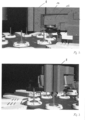
- Figure 2 shows a machining of a workpiece 7 with the whirling-turning-milling unit 8 and the guide bush carrier 12.
- the whirling-turning-milling unit 8 comprises a housing 9 on which various tools 9 are arranged.
- the tools 9 are a whirling unit 15, a milling unit 16 and a turning unit 17.
- One end of the workpiece 7 is clamped in the collet 14 of the workpiece spindle 3.
- the other end of the workpiece 7 is machined with the whirling unit 15, with the whirling unit 15 being moved in the Z axis.
- a controlled movement of the guide bush carrier 12 takes place so that sufficient guidance of the workpiece 7 is always achieved.
- the guide bush 13 is therefore always located at a distance (e.g. 1-2 mm) below the whirling unit 15 and is moved along in the Z axis during machining with the tool 9 so that the workpiece 7 is sufficiently guided relatively close to the machining area.
- the guide bush carrier 12 therefore moves in parallel during machining of the workpiece 7 with the tool 9 of the whirling-turning-milling unit 8.
- the controlled guidance of the guide bush carrier 13 stabilizes the workpiece 7 during machining. Relatively long workpieces 7 can thus be machined, since the guide bush carrier 13 guides the workpiece 7 between the collet 14 of the workpiece spindle 3 and the respective tool 9 in the manner of a plain bearing.
- Figure 3 shows a further view of the whirling-turning-milling unit 8 and the guide bush carrier 12.
- a first whirling-turning-milling unit 8 is arranged on the slide 5 (position 3.1) and the associated first guide bush carrier 12 is arranged on the slide 5 (position 3.2).
- a second whirling-turning-milling unit 8 is arranged on the slide 5 (position 4.1) and the associated second guide bush carrier 12 is arranged on the slide 5 (position 4.2).
- a workpiece 7 is clamped in each collet 14 of the workpiece spindle 3. During machining in position no. 3 and position no. 4, the workpieces 7 are additionally held by the guide bush carriers 12.
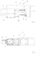
- FIG 4 shows the whirling-turning-milling unit 8 and the guide bush carrier 12 during the machining of a workpiece 7.
- the whirling-turning-milling unit 8 has a U-shaped housing 10, with a first leg 20 a whirling unit 15 and a rotating unit 17 and a milling unit 16 are arranged on the opposite second leg 21.
- the two legs 20, 21 are connected to one another by a web-like connecting body 22 and together form the U-shape.
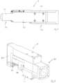
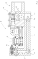
- FIG. 5 shows the whirling-turning-milling unit 8, which has a housing 10 that includes a first leg 20, a connecting body 22 and a second leg 21.
- the first leg 20 is located on the motor side 23.
- the driving force is guided through the connecting body 22 via a gear device and delivered to the rotating driven tool 9 (milling unit 16) in the second leg 21, i.e. on the gear side 24.
- the housing 10 of the whirling-turning-milling unit 8 thus serves not only as a holder for the individual tools 9, but also as a housing for a gear device for the rotating driven tool 9 on the second leg 21.
- Figure 6 shows the whirling-turning-milling unit 8 in a bottom view.
- the individual tools 9 are arranged on the two spaced legs 20, 21 without causing a collision.
- the whirling-turning-milling unit 8 has fastening devices on the underside in order to be fastened to a tool carrier or a tool carriage 5.
- the housing 10 of the whirling-turning-milling unit 8 comprises the first leg 20, the connecting body 22, and the second leg 21.
- the first leg 20 forms the first component
- the second leg 21 and the connecting body 22 form a further component.
- the housing 10 can, for example, be formed in one piece or consist of several parts.
- Figure 8 shows a perspective view of the whirling-turning-milling unit 8.
- the whirling unit 8 is slightly rotated relative to the housing 10. This is necessary if a thread with a certain pitch is to be whirled into the workpiece 7.
- Two pinions 26 are arranged on the input shaft 28, whereby the power is transmitted to the vortex unit 15 via a first toothed belt 30 and to a shaft 25 via a second toothed belt 27.
- the rotating shaft 25 is arranged in the connecting body 22 and creates a rotating connection between the motor side 23 and the gear side 24.
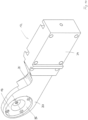
- Figure 11 shows a perspective view of the guide bush carrier 12.
- the guide bush carrier 12 has a fastening part 34 with which the guide bush carrier 12 is fastened to a tool carriage 7. Furthermore, the guide bush carrier 12 has a guide head 33 which is self-supporting and has a holder for the guide bush 13.
- the self-supporting guide head 33 holds and/or guides the workpiece 7 during machining with the whirling-turning-milling unit 8 without the guide bush carrier 12 colliding with the whirling-turning-milling unit 8.
- the guide head 33 has a bowl-like recess 35 on the underside in the area of the holder for the guide bush 13, which corresponds approximately to the shape of the workpiece spindle 3 or the collet 14 of the workpiece spindle 3.
- the special shape of the recess 35 thus makes it possible to move the guide bush 13 relatively close to the workpiece spindle 3 during machining of the workpiece without collision.
- the guide bush carrier 12 has a lateral recess 36 in the area of the guide head 33, which also prevents a collision.
- Figure 11 shows a top view of the guide bush carrier 12.
- the guide bush carrier 12 In the area of the guide head 33, the guide bush carrier 12 has numerous bevelled or chamfered edges, which prevent possible collisions with other components.
- FIG. 12 a bottom view of the guide bush carrier 12 is shown, wherein the guide bush 13 is arranged detachably with a screw connection 37 on the guide head 33 of the guide bush carrier 12.
- the detachable screw connection 37 allows numerous different guide bushes 13 with different diameters to be inserted into the guide bush carrier 12.
Landscapes
- Engineering & Computer Science (AREA)
- Mechanical Engineering (AREA)
- Turning (AREA)
Priority Applications (4)
| Application Number | Priority Date | Filing Date | Title |
|---|---|---|---|
| EP24159439.9A EP4434655A1 (fr) | 2023-03-15 | 2023-03-15 | Dispositif pour usiner des pièces sur un tour multibroche |
| EP23161971.9A EP4431209A1 (fr) | 2023-03-15 | 2023-03-15 | Dispositif et procédé d'usinage de pièces sur un tour multibroches |
| CN202480016840.9A CN120857995A (zh) | 2023-03-15 | 2024-03-12 | 用于在多轴车床上加工工件的装置和方法 |
| PCT/EP2024/056570 WO2024189032A1 (fr) | 2023-03-15 | 2024-03-12 | Dispositif et procédé d'usinage de pièces sur un tour multibroche |
Applications Claiming Priority (1)
| Application Number | Priority Date | Filing Date | Title |
|---|---|---|---|
| EP23161971.9A EP4431209A1 (fr) | 2023-03-15 | 2023-03-15 | Dispositif et procédé d'usinage de pièces sur un tour multibroches |
Related Child Applications (2)
| Application Number | Title | Priority Date | Filing Date |
|---|---|---|---|
| EP24159439.9A Division-Into EP4434655A1 (fr) | 2023-03-15 | 2023-03-15 | Dispositif pour usiner des pièces sur un tour multibroche |
| EP24159439.9A Division EP4434655A1 (fr) | 2023-03-15 | 2023-03-15 | Dispositif pour usiner des pièces sur un tour multibroche |
Publications (1)
| Publication Number | Publication Date |
|---|---|
| EP4431209A1 true EP4431209A1 (fr) | 2024-09-18 |
Family
ID=85704018
Family Applications (2)
| Application Number | Title | Priority Date | Filing Date |
|---|---|---|---|
| EP24159439.9A Pending EP4434655A1 (fr) | 2023-03-15 | 2023-03-15 | Dispositif pour usiner des pièces sur un tour multibroche |
| EP23161971.9A Pending EP4431209A1 (fr) | 2023-03-15 | 2023-03-15 | Dispositif et procédé d'usinage de pièces sur un tour multibroches |
Family Applications Before (1)
| Application Number | Title | Priority Date | Filing Date |
|---|---|---|---|
| EP24159439.9A Pending EP4434655A1 (fr) | 2023-03-15 | 2023-03-15 | Dispositif pour usiner des pièces sur un tour multibroche |
Country Status (3)
| Country | Link |
|---|---|
| EP (2) | EP4434655A1 (fr) |
| CN (1) | CN120857995A (fr) |
| WO (1) | WO2024189032A1 (fr) |
Citations (3)
| Publication number | Priority date | Publication date | Assignee | Title |
|---|---|---|---|---|
| DE3721732A1 (de) * | 1987-07-01 | 1989-01-12 | Gwt Ges Fuer Gewindewirbel & T | Vorrichtung zum gewinde-wirbelschneiden |
| EP3208016A2 (fr) | 2016-02-18 | 2017-08-23 | Schiess Tech GmbH | Porte-outil, chariot porte-outil et tour à barre |
| DE102017121295A1 (de) | 2017-09-14 | 2019-03-14 | Index-Werke Gmbh & Co. Kg Hahn & Tessky | Mehrspindeldrehmaschine |
-
2023
- 2023-03-15 EP EP24159439.9A patent/EP4434655A1/fr active Pending
- 2023-03-15 EP EP23161971.9A patent/EP4431209A1/fr active Pending
-
2024
- 2024-03-12 WO PCT/EP2024/056570 patent/WO2024189032A1/fr not_active Ceased
- 2024-03-12 CN CN202480016840.9A patent/CN120857995A/zh active Pending
Patent Citations (3)
| Publication number | Priority date | Publication date | Assignee | Title |
|---|---|---|---|---|
| DE3721732A1 (de) * | 1987-07-01 | 1989-01-12 | Gwt Ges Fuer Gewindewirbel & T | Vorrichtung zum gewinde-wirbelschneiden |
| EP3208016A2 (fr) | 2016-02-18 | 2017-08-23 | Schiess Tech GmbH | Porte-outil, chariot porte-outil et tour à barre |
| DE102017121295A1 (de) | 2017-09-14 | 2019-03-14 | Index-Werke Gmbh & Co. Kg Hahn & Tessky | Mehrspindeldrehmaschine |
Also Published As
| Publication number | Publication date |
|---|---|
| CN120857995A (zh) | 2025-10-28 |
| WO2024189032A1 (fr) | 2024-09-19 |
| EP4434655A1 (fr) | 2024-09-25 |
Similar Documents
| Publication | Publication Date | Title |
|---|---|---|
| EP0968069B1 (fr) | Machine-outil | |
| EP1193027B1 (fr) | Tour | |
| EP1260307B1 (fr) | Machine-outil et procédé d'usinage d'une pièce en forme de barre | |
| EP1910003B1 (fr) | Machine universelle pour usinage avant traitement de pignons coniques et procede correspondant | |
| DE102010010901B4 (de) | Verfahren und Vorrichtung zum Feinbearbeiten einer Kurbelwellenlagerbohrung | |
| DE4027687C2 (fr) | ||
| EP1820592A2 (fr) | Dispositif destiné à la fabrication par enlèvement de matière de profils filetés | |
| DE10040224A1 (de) | Werkzeugmaschine | |
| EP1854580A2 (fr) | Machine-outil | |
| DE2553216A1 (de) | Mehrkant-drehmaschine | |
| DE4236866A1 (de) | Drehmaschine | |
| EP0260692A2 (fr) | Machine-outil avec un porte-broche à forer et à fraiser à déplacement dans la direction Z sur un châssis de machine | |
| EP3081324A1 (fr) | Tour à poupée mobile comprenant deux axes d'usinage à commande numérique et procédé destiné à usiner des pièces sur un tour a poupée mobile comprenant deux axes d'usinage à commande numérique | |
| EP1025953A1 (fr) | Machine-outil | |
| DE3516100A1 (de) | Verfahren zur spanabhebenden bearbeitung von drehteilen, vorzugsweise von wellen, insbesondere von kurbelwellen, sowie vorrichtung zur durchfuehrung eines solchen verfahrens | |
| EP4431209A1 (fr) | Dispositif et procédé d'usinage de pièces sur un tour multibroches | |
| DE10145674B4 (de) | Werkzeugmaschine zur Bearbeitung eines stangenförmigen Werkstücks | |
| DE19936468A1 (de) | Drehmaschine | |
| DE10331985A1 (de) | Vorrichtung zur Innenbearbeitung von rohrförmigen Werkstücken und Zwangsführungseinrichtung | |
| EP0717669B1 (fr) | Dispositif d'usinage de pieces sur un tour automatique a commande numerique et tour automatique a commande numerique | |
| DE4022572A1 (de) | Drehmaschine mit doppelrevolver | |
| DE102005039089A1 (de) | Drehmaschine | |
| DE102021003700A1 (de) | Vorrichtung und Verfahren zur spanenden Drehbearbeitung von hohlzylinderförmigen Werkstücken | |
| DE10206949C1 (de) | Zweispindel-Drehmaschine | |
| EP3208016A2 (fr) | Porte-outil, chariot porte-outil et tour à barre |
Legal Events
| Date | Code | Title | Description |
|---|---|---|---|
| PUAI | Public reference made under article 153(3) epc to a published international application that has entered the european phase |
Free format text: ORIGINAL CODE: 0009012 |
|
| STAA | Information on the status of an ep patent application or granted ep patent |
Free format text: STATUS: REQUEST FOR EXAMINATION WAS MADE |
|
| 17P | Request for examination filed |
Effective date: 20240306 |
|
| AK | Designated contracting states |
Kind code of ref document: A1 Designated state(s): AL AT BE BG CH CY CZ DE DK EE ES FI FR GB GR HR HU IE IS IT LI LT LU LV MC ME MK MT NL NO PL PT RO RS SE SI SK SM TR |