EP4431228B1 - Partie de boîtier pour un dispositif de serrage et/ou de freinage pneumatique - Google Patents
Partie de boîtier pour un dispositif de serrage et/ou de freinage pneumatique Download PDFInfo
- Publication number
- EP4431228B1 EP4431228B1 EP23161999.0A EP23161999A EP4431228B1 EP 4431228 B1 EP4431228 B1 EP 4431228B1 EP 23161999 A EP23161999 A EP 23161999A EP 4431228 B1 EP4431228 B1 EP 4431228B1
- Authority
- EP
- European Patent Office
- Prior art keywords
- housing part
- clamping
- contact surface
- spring plate
- spring
- Prior art date
- Legal status (The legal status is an assumption and is not a legal conclusion. Google has not performed a legal analysis and makes no representation as to the accuracy of the status listed.)
- Active
Links
Images




Classifications
-
- B—PERFORMING OPERATIONS; TRANSPORTING
- B23—MACHINE TOOLS; METAL-WORKING NOT OTHERWISE PROVIDED FOR
- B23Q—DETAILS, COMPONENTS, OR ACCESSORIES FOR MACHINE TOOLS, e.g. ARRANGEMENTS FOR COPYING OR CONTROLLING; MACHINE TOOLS IN GENERAL CHARACTERISED BY THE CONSTRUCTION OF PARTICULAR DETAILS OR COMPONENTS; COMBINATIONS OR ASSOCIATIONS OF METAL-WORKING MACHINES, NOT DIRECTED TO A PARTICULAR RESULT
- B23Q16/00—Equipment for precise positioning of tool or work into particular locations not otherwise provided for
- B23Q16/02—Indexing equipment
- B23Q16/08—Indexing equipment having means for clamping the relatively movable parts together in the indexed position
- B23Q16/10—Rotary indexing
- B23Q16/107—Rotary indexing clamping with a drum brake
-
- F—MECHANICAL ENGINEERING; LIGHTING; HEATING; WEAPONS; BLASTING
- F16—ENGINEERING ELEMENTS AND UNITS; GENERAL MEASURES FOR PRODUCING AND MAINTAINING EFFECTIVE FUNCTIONING OF MACHINES OR INSTALLATIONS; THERMAL INSULATION IN GENERAL
- F16D—COUPLINGS FOR TRANSMITTING ROTATION; CLUTCHES; BRAKES
- F16D55/00—Brakes with substantially-radial braking surfaces pressed together in axial direction, e.g. disc brakes
- F16D55/02—Brakes with substantially-radial braking surfaces pressed together in axial direction, e.g. disc brakes with axially-movable discs or pads pressed against axially-located rotating members
- F16D55/04—Brakes with substantially-radial braking surfaces pressed together in axial direction, e.g. disc brakes with axially-movable discs or pads pressed against axially-located rotating members by moving discs or pads away from one another against radial walls of drums or cylinders
- F16D55/06—Brakes with substantially-radial braking surfaces pressed together in axial direction, e.g. disc brakes with axially-movable discs or pads pressed against axially-located rotating members by moving discs or pads away from one another against radial walls of drums or cylinders without self-tightening action
- F16D55/10—Brakes actuated by a fluid-pressure device arranged in or on the brake
- F16D55/12—Brakes actuated by a fluid-pressure device arranged in or on the brake comprising an expansible fluid-filled flexible member coaxial with the brake
-
- F—MECHANICAL ENGINEERING; LIGHTING; HEATING; WEAPONS; BLASTING
- F16—ENGINEERING ELEMENTS AND UNITS; GENERAL MEASURES FOR PRODUCING AND MAINTAINING EFFECTIVE FUNCTIONING OF MACHINES OR INSTALLATIONS; THERMAL INSULATION IN GENERAL
- F16D—COUPLINGS FOR TRANSMITTING ROTATION; CLUTCHES; BRAKES
- F16D65/00—Parts or details
- F16D65/14—Actuating mechanisms for brakes; Means for initiating operation at a predetermined position
- F16D65/16—Actuating mechanisms for brakes; Means for initiating operation at a predetermined position arranged in or on the brake
- F16D65/18—Actuating mechanisms for brakes; Means for initiating operation at a predetermined position arranged in or on the brake adapted for drawing members together, e.g. for disc brakes
- F16D65/186—Actuating mechanisms for brakes; Means for initiating operation at a predetermined position arranged in or on the brake adapted for drawing members together, e.g. for disc brakes with full-face force-applying member, e.g. annular
Definitions
- the invention relates to a housing part for a pneumatic clamping and/or braking device and a pneumatic clamping and/or braking device with such a housing part.
- processing machines in particular work spindles or other machine tools, are used which process material from a workpiece using tools attached to a shaft, in particular to give it the desired shape.
- the shaft can be a rotational axis or pivoting axis of such a machine.
- rotating or pivoting tables are used with a shaft to place tools or workpieces in the appropriate processing position or to move workpieces at appropriate speeds.
- a high speed of the shaft is one of the prerequisites for precise and efficient processing.
- Emergency or safety systems therefore have the task of stopping the shaft or holding it in a fixed position and thus fixing it in the event of a malfunction or failure of the system, such as a power failure or cable break.
- Common machining centers are equipped with electromagnetic, hydraulic, or pneumatic clamping and/or braking devices. These devices feature a friction lining that can be frictionally connected to the shaft via force transmission. This allows the shaft to be clamped at varying speeds.
- hydraulic clamping devices In hydraulic clamping devices, a chamber is pressurized with hydraulic oil, clamping the rotating shaft or disc. Passive hydraulic clamps are also known. However, such hydraulic clamps have long response times, or short response times require considerable effort. Furthermore, the hydraulic material, especially hydraulic valves and hydraulic pipes, is expensive and requires longer assembly times. The hydraulic oil also requires additional effort to maintain cleanliness in the area surrounding a hydraulic clamp.
- EP 1 585 616 B1 and EP 1 651 881 B1 describe pneumatic clamping devices with two annular spring plates that are inserted into a housing of the clamping device and form a pressure chamber therein, which can be pressurized with compressed air or vented and vented in order to change the bending of the spring plates and thereby switch between a closed state of the clamping devices, in which an object to be clamped, such as a rotatable shaft, is clamped, and an open state of the clamping devices, in which the object is free.
- the desired opening and closing function of the pneumatic clamping devices cannot be achieved axially symmetrically over the circumference of the annular spring plates. For example, an uneven clamping force distribution on the circumference of the shaft and consequent damage to the shaft have been observed.
- a device according to the preamble of claim 1 is known from CN 107 127 360 A known.
- the object of the invention is to enable a pneumatic clamping and/or braking device to reliably achieve its desired symmetrical opening and closing function.
- a housing part for a pneumatic clamping and/or braking device comprising: an annular recess for clamping an annular spring plate between a first contact surface of the housing part defined by the recess and a second contact surface of the housing part defined by the recess; a clamping element with a clamping surface which is designed, when the spring plate is clamped in the recess between the first contact surface and the second contact surface, such that a first end of the spring plate is supported on the first contact surface, the spring plate extends from the first contact surface to the second contact surface, and a second end of the spring plate presses on the second contact surface to transmit a clamping and/or braking force to an object to be clamped and/or braked; wherein the housing part comprises a first latching means and a second latching means, wherein, when the spring plate is clamped in the recess between the first contact surface and the second contact surface, the first latching means is designed to latch the first
- a clamping and/or braking device for clamping and/or braking an object to be clamped and/or braked, the device comprising: a housing comprising a first housing part according to the invention and a second housing part according to the invention, wherein the two housing parts are arranged and fastened to one another in such a way that the recesses of the first and second housing parts together form an interior space within the housing; a spring (e.g., a spiral spring, such as a leaf spring) arranged in the interior space, comprising a first annular spring plate (e.g., a spiral spring, such as a leaf spring) and a second annular spring plate (e.g., a spiral spring, such as a leaf spring), wherein the spring plates are arranged within the interior space in such a way that at least one pressure chamber is formed in the interior space, which is at least partially delimited by the spring plates, wherein the pressure chamber can be ventilated or vented and can be subject
- transverse bending; bending perpendicular to the longitudinal axis of the spring plate; the longitudinal axis connects the two ends of each spring plate) is variable and thereby the device can be switched between an open state in which the object is spaced from the clamping surfaces and a closed state in which one or more of the clamping surfaces exert a clamping and/or braking force on the object transmitted, changes.
- the device can change from the closed state to the open state or vice versa.
- the object In the open state of the device, the object is freely movable (e.g., freely rotatable about a rotational axis or linearly movable along the axis), whereas in the closed state of the device, the object is clamped and/or braked and is therefore not freely movable (e.g., not rotatable about the rotational axis or not linearly movable along the axis).
- the present invention is based on the inventors' finding that the axial positioning of the spring plates within the housing of the clamping and/or braking device is of crucial importance for the opening and closing function of the clamping and/or braking device.
- the inventors recognized that the axial positioning of the spring plates during assembly previously depended significantly on the axial press-in pressure and that the spring plates could therefore assume slightly different axial positions within the housing.
- the inventors recognized that a well-defined and symmetrical positioning of the spring plates within the housing should be reliably achieved in order to reliably achieve the desired symmetrical opening and closing function of the clamping and/or braking device.
- Such a well-defined and symmetrical positioning of the spring plates within the housing previously placed high demands on the axial pressing of the springs into the housing during assembly and has proven difficult and complex in practice.
- a housing part comprising a first latching means and a second latching means, each designed to latch a different end of a clamped spring plate, achieves a predetermined axial positioning of the spring plates within a housing of a pneumatic clamping and/or braking device.
- This positioning no longer depends significantly on the axial press-in force during assembly, but rather a repeatable, well-defined, and symmetrical positioning of the spring plates within the housing of the clamping and/or braking device is achieved.
- These latching means have also proven themselves in practice during assembly, as they actually simplify the assembly of the spring plates.
- the latching means provide further advantages of the type described below, such as improved sealing within the housing, so that the latching means have a variety of positive effects on the operation of the overall system of the clamping and/or braking device.
- the first engagement means comprises a first projection and a first stop, each of which delimits the first contact surface in such a way that the first engagement means is designed to engage the first end of the spring plate between the first projection and the first stop in the region of the first contact surface.
- the second engagement means can preferably comprise a second projection and a second stop, each of which delimits the second contact surface in such a way that the second engagement means is designed to engage the second end of the spring plate between the second projection and the second stop in the region of the second contact surface.
- Each of the projections can include a height transition at the transition from the projection to the associated or adjacent contact surface.
- Each of the projections can include a step or ramp as a height transition.
- the ramp can be an inclined plane, but can also have slopes of other shapes, such as a curve. Other configurations of the projections are also conceivable.
- each of the projections can protrude into the recess (11) by 0.025 mm to 0.15 mm, preferably 0.05 mm to 0.1 mm, particularly preferably by 0.1 mm or 0.05 mm relative to the respective contact surface in a radial direction of the annular recess.
- Such protrusion by the projections can be particularly advantageous for the reliable engagement of the spring plates with regard to common shortening of the spring during operation, on the one hand, and the easy insertion of the spring plates into the housing parts, on the other.
- the annular recess can define an annular opening in the housing part, wherein the annular opening is formed between a first annular edge of the housing part and a second annular edge of the housing part.
- the first projection can be arranged between the first annular edge and the first contact surface on an inner side of the housing part in the region of the recess and optionally extend from the first annular edge to the first contact surface. The height transition of the first projection can adjoin the first contact surface.
- the height transition (e.g., the step or ramp) of the first projection can preferably be arranged on the inner side of the housing part in the region of the recess, and the first projection can extend over this distance.
- the first projection can extend continuously from the first annular edge to the Height transition.
- the second projection can preferably be arranged between the second annular edge and the second contact surface on an inner side of the housing part in the region of the recess and can optionally extend from the second annular edge to the second contact surface.
- the height transition of the second projection can border the second contact surface.
- the height transition (e.g.
- the step or ramp) of the second projection can preferably be arranged on the inner side of the housing part in the region of the recess at a distance of 1 mm to 1.8 mm, preferably 1 mm to 1.5 mm, particularly preferably 1.2 mm or 1.1 mm from the second annular edge, and the second projection can extend over this distance.
- the second projection can extend continuously from the second annular edge to the height transition.
- Such an arrangement of the projections or steps or ramps can be particularly advantageous for the reliable positioning of the spring plates within the recess or the housing with regard to usual operating parameters of the clamping device on the one hand and the easy insertion of the spring plates into the housing parts on the other.
- the distance between the first projection and the first stop and the distance between the second projection and the second stop can be 1 mm to 1.5 mm, 1.1 mm to 1.4 mm, preferably 1.2 mm, respectively, which is particularly adapted for effective engagement of springs with common thicknesses and common rubber coatings.
- the invention relates to a housing part for a pneumatic clamping and/or braking device and a pneumatic clamping and/or braking device with a housing part according to the invention.
- FIGS. 1A to 5A show schematic cross sections through such a pneumatic clamping device 10 according to the invention with a housing 3 which comprises two housing parts 3a, 3b according to the invention, and with a spring 1 arranged in the housing 3 which comprises at least two annular spring plates 1a, 1b.
- the clamping device 10 comprises the following: a housing 3 comprising first and second housing parts 3a, 3b according to the invention, as described below in connection with Figures 6A and 6B described, wherein the two housing parts 3a, 3b are arranged relative to one another and fastened to one another in such a way that recesses of the first and second housing parts 3a, 3b together form an interior space 13 within the housing 3; a spring 1 arranged in the interior 13 comprising a first annular spring plate 1a and a second annular spring plate 1b, wherein the spring plates 1a, 1b are arranged within the interior 13 in such a way that at least one pressure chamber 2, 4 is formed in the interior 13, which is at least partially delimited by the spring plates 1a, 1b, wherein the pressure chamber 2, 4 can be vented or vented (by means of an opening I, II and optionally a connection to a compressed air pump 6) and can be subjected to overpressure of a pressure medium that can be supplied to the housing 3, wherein the first spring plate
- the clamping force or effect of the clamping surface 7 on the object 5 to be clamped takes place in a clamping plane which is spanned by two vectors, each of which forms a radius of the annular spring plates 1a, 1b or annular recess 11 (cf. Fig. 5A ).
- the axis 9 can be referred to as the main axis of the clamping device 10, which runs perpendicular to the clamping plane.
- the clamping device 10 can be designed rotationally symmetrical about this main axis 9.
- the main axis 9 can run approximately or exactly centrally through an opening of the clamping device 10 (opening 14 in Fig. 5B ).
- the object 5 to be clamped for example a rotatable shaft of a machine or a table, is placed within the opening 14 and the clamping force of the clamping device is therefore directed radially inwards towards the main axis 9 (perpendicular to the main axis 9) within the clamping plane.
- Figures 1B , 4B the object 5 to be clamped is placed outside the clamping device 10 and the clamping force of the clamping device is therefore directed radially outwards away from the main axis 9 (perpendicular to the main axis 9) within the clamping plane.
- Fig. 1A , 2A , 3A , 4A The clamping element 8 is located between spring 1 and opening 14 or main axis 9.
- the object 5 to be clamped at least partially surrounds the clamping device 10, so that the clamping element 8 is located between the object 5 and the opening 14 or main axis 9.
- a component which at least partially fills the opening 14 and through which the main axis 9 extends can be introduced into the opening 14.
- venting an inner pressure chamber 2 of the spring 1 and ventilating an outer pressure chamber 4 can lead to at least partial relaxation of the spring 1 while the spring 1 presses against the radial contact surfaces, the distance between which increases slightly, so that the housing 3 is elastically deformed in the region of the clamping element 8 or the clamping surface 7 and the clamping surface 7 therefore touches the object 5 and is pressed against the object 5 with a (predefined) clamping force in order to clamp the object 5.
- the object 5 is clamped and the clamping device 10 is in the closed state, as in Figures 1A and 1B shown. In the closed state of the device 10, the spring 1 can still be slightly bent even after partial relaxation in order to be firmly fixed in the housing 3 in this state.
- the clamping element 8 can be an elastic element, such as a spring fork, which, in the pressure-free initial state of the device 10, is brought from an initial position in which the elastic element is relaxed into a tensioned position by the spring force of the (slightly) bent spring 1, for example by bending the spring fork 8, until an equilibrium is established in the pressure-free initial state between a restoring force of the elastic element 8 and the spring force of the spring 1. In this equilibrium, the clamping surface 7 can press against the object 5.
- an elastic element such as a spring fork
- the clamping device 10 can also be operated with a single pressure chamber, which can be, for example, the inner pressure chamber 2 or the outer pressure chamber 4.
- Figures 2A and 2B show the clamping devices 10 from the Figures 1A and 1B in each case in the open state in which the clamping surface 7 does not touch the circumference of the object 5 or is spaced from the circumference of the object 5.
- the inner pressure chamber 2 can be connected via an opening in the housing 3 to an air connection I (also referred to as "Open"), to which a compressed air pump 6 can be connected.
- I also referred to as "Open”
- the spring 1 By applying compressed air (for example 4 bar or 6 bar) to the inner pressure chamber 2 by the compressed air pump 6 and venting the outer pressure chamber 4, the spring 1 is, compared to the closed state of Fig. 1A, 1B , more strongly (convexly) bent or tensioned, resulting in a radial shortening of the spring 1 or the distance between the two contact surfaces.
- the clamping surface 7 lifts off the object 5 to release the clamping.
- the object 5 is freely movable (e.g., rotatable about axis 9 or linearly movable along axis 9) and the clamping device 10 is open.
- the device 10 can be switched back and forth between the closed state and the open state.
- Such pneumatic clamps 10 have a number of advantages over hydraulic clamps.
- a spring 1 with spring plates 1a, 1b, and compressed air for example, very short reaction times are achieved when switching between the open and closed state and also a secure clamping of the object 5 is ensured.
- the spring 1 can preferably be designed in the shape of a plate, as in Fig. 5 shown in more detail, wherein two superimposed spring plates 1a, 1b form the spring 1 and the inner pressure chamber 2 of the spring 1 between the plates 1a, 1b.
- the plates 1a, 1b can also be annular, as in Fig. 5 shown, and can optionally have additional radial slots, so that a change in the inner diameter is possible with particularly low forces.
- the spring plates 1a, 1b can be coated with rubber, at least in the area of the slots, in order to ensure the tightness required for the compressed air. to manufacture.
- the spring plates 1a, 1b can also be completely coated with rubber.
- the spring plates 1a, 1b are generally designed to be pressure-resistant and elastically flexible and are arranged in the housing 3 of the clamping device 10 in such a way that the inner pressure chamber 2 is formed within the spring 1 between the spring plates 1a, 1b, and the outer pressure chamber 4 is formed between each spring plate 1a, 1b and the housing 3 or the housing parts 3a, 3b of the clamping device 10.
- Figure 5 shows a three-dimensional view of a clamping device 10 similar to Figures 1A and 2A .
- the spring 1 By venting or applying compressed air to the outer pressure chamber 4 and venting the inner pressure chamber 2, as in Fig. 1A As shown, the spring 1 is at least partially relaxed and exerts a clamping force on the object 5 to be clamped, in particular on the circumference of a shaft 5. In the event of a power or pressure failure, the object 5 is clamped or the shaft 5 is immediately brought to a standstill, thus providing a safety clamp.
- such pneumatic clamps 10 can achieve holding torques of several 100 Nm and up to several 1000 Nm, which can be increased by additionally pressurizing the outer pressure chamber 4 with compressed air, as in Fig. 1A by a pressure pump 6 (booster).
- compressed air of a few bar is sufficient to provide several times the holding torque achieved without a booster.
- Pneumatic clamps also require lower costs and assembly effort than hydraulic clamps, and the use of compressed air eliminates any additional effort required to maintain cleanliness within the system.
- Such pneumatic clamps also allow for compact dimensions, as minimal transverse deflection and minimal (changes in) longitudinal expansion of the spring, and thus small pressure chamber volumes, are sufficient to generate the required clamping forces.
- the spring 1 In the initial pressureless state, the spring 1 can be bent to varying degrees (transversely) and thus be shortened radially to varying degrees.
- the inside of the housing 3 can be adapted to the curvature of the spring plates 1a, 1b or define it.
- a corresponding stop surface for the spring plates 1a, 1b can be formed, for example, by an inner housing wall.
- the inner housing wall can be designed to complement (e.g., concave) a (e.g., convex) curvature of the spring plates 1a, 1b.
- the spring 1 is generally slightly elastically bent (e.g. convex) or pre-tensioned in the pressure-free initial state and the clamping devices 10 can be closed ( Fig. 1A, 1B ).
- the clamping device 10 is only opened by the application of force from the inside by applying compressed air to the inner pressure chamber 2 ( Fig. 2A, 2B ).
- the spring 1 In the initial pressure-free state, the spring 1 is usually slightly bent, so that in the event of a clamping action or in the event of a pressure drop, the spring force generated by the energy stored in the spring 1 is transferred to the object 5 to be clamped as a clamping force in order to clamp the object 5.
- the spring 1, with the same housing 3 can be more transversely curved outwards in the depressurized initial state and thus more radially shortened than with passive clamping devices.
- This smaller radial expansion of the spring plates 1a, 1b in the depressurized initial state can lead to an open state of the clamping device 10 in the depressurized initial state.
- the spring plates 1a, 1b are elastically bent and press against the contact surfaces so that the spring is fixed in the housing.
- the interior of the housing or the recesses can absorb the greater curvature caused by plastic deformation in the initial state.
- the clamping force must now be actively induced from the outside, as in Fig. 4A and 4B shown to transfer the clamp into the closed state.
- compressed air is introduced into the external pressure chamber 4 by a compressed air pump 6, thus pressurizing the spring 1 from the outside in such a way that the spring 1 is actively relaxed, the curvature of the spring 1 is reduced, the distance between the two contact surfaces is increased, and the housing 3 in the area of the clamping element 8 or the clamping surface 7 elastically deformed, so that the clamping surface 7 touches the object 5 and exerts a clamping force on the object 5, thereby clamping the object 5.
- the active clamping device 10 is then in the closed state.
- an active or passive clamping system 10 is used. If a safety clamp is primarily desired, a passive clamping device is generally used. With such pneumatic passive clamping systems, it is possible to generate a predetermined clamping force even in a depressurized state when the device is appropriately mounted in an overall device, which clamping force is applied to the object 5 to be clamped. By applying overpressure or negative pressure, the forces transmitted to this object can be increased, reduced, or completely eliminated, which opens up a wide variety of applications. If, on the other hand, the clamping device is primarily intended to carry out a deliberate work process, such as a tool change, an active clamping device is generally used.
- the housing 3 of the clamping devices 10 comprises two housing parts 3a, 3b according to the invention, which are fastened to one another by fastening means, such as screws, and are mounted such that, in the mounted state, the two housing parts 3a, 3b define an interior space 13 between the housing parts 3a, 3b within the housing 3, in which the spring 1 together with its annular spring plates 1a, 1b are arranged.
- the housing parts 3a, 3b each define a recess 11, which is also annular and which serves to receive the annular spring plates 1a, 1b, as shown in Figures 5A, 5B shown.
- At least a part of the first contact surface 101 can run (substantially) perpendicular to the radial direction R of the annular recess 11 and/or a part of the second contact surface 102 can run (substantially perpendicular) to the radial direction R of the annular recess 11.
- the housing 3 Through the center of the housing 3 extends an opening 14 (Fig. 5B) into which the object 5 to be clamped, such as a shaft, can be inserted.
- the housing can extend up to 360° around this opening and at least partially encloses the object 5 in at least one plane, which is referred to as the clamping plane.
- the central main axis 9 of the clamping devices runs centrally through the opening 14 and perpendicular to the clamping plane.
- the main axis 9 runs centrally through the shaft along its longitudinal axis.
- the Clamping surfaces 7 which, in the event of elastic deformation of the housing 3 in the region of the clamping element 8 or the clamping surface 7, exert the clamping force on the outer circumference of the object 5 and can thereby clamp the object 5.
- a symmetrical distribution of the clamping force along the clamping surface 7 or along the circumference of the object 5 is desirable.
- An asymmetrical distribution of the clamping force can lead to damage to the object 5.
- one or both contact surfaces 101, 102 are circular within the clamping plane.
- the clamping surface 7 is circular within the clamping plane.
- the clamping element 8 can be annular. All annular or circular components described herein can each individually or in combination have as their center the intersection point of the main axis 9 with the clamping plane (e.g., the center point of the opening 14).
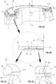
- Figure 5B shows one of the two housing parts 3a (here the upper housing part 3a from Fig. 5A ), as well as one of the two spring plates 1a, 1b of the spring 1.
- the illustrated spring plate 1a of the spring 1 extends from a first contact surface 101 within the housing part 3a to a second contact surface 102 within the housing part 3a and can touch it.
- the first contact surface 101 is arranged radially further outward from the center of the opening 14 than the second contact surface 102.
- Figure 5C shows the section of the Figure 5B illustrated housing part 3a in which the upper plate 1a of the spring 1 meets the first contact surface 101 and is preferably in contact with it.
- Figure 5D shows the section of the Figure 5B illustrated housing part 3a in which the upper plate 1a of the spring 1 meets the second contact surface 102 and is preferably in contact with it.
- one or more further components it is also possible for one or more further components to be located radially between the spring plate 1a and one or more of the contact surfaces 101, 102, via which the spring plate 1a exerts its spring force on the contact surfaces 101, 102.
- the housing part 3a shown has the shape used in the prior art. As shown in Figures 5B, 5D As can be seen, the inner sides of the housing part 3a between which the spring plate 1a is clamped in the recess are straight or flat. Each of the plates of the spring 1 is inserted in the direction of the main axis 9 of the clamping devices 10 through the opening 12 into the recess 11 of the respective housing part during assembly along straight or flat inner surfaces of the housing part 3a until the respective plate at the end of each of the both contact surfaces 101, 102 abut against a stop 112, 122 and therefore cannot be inserted further into the recess 11. Since the expansion of the spring plate 1a in the clamping plane or in the radial direction of the annular recess is greater than the expansion of the interior defined by the housing part, the plate 1a is bent or prestressed in the pressure-free initial state.
- the plates 1a, 1b of the spring 1 are positioned during assembly depending on the axial press-in force and are therefore not always axially positioned the same in the housing parts 3a, 3b.
- the spring plates 1a, 1b can tilt, be inserted into the housing parts at different depths, or bend to different degrees. Due to their crucial importance for the opening and closing function of the clamping devices 10, the variation in the positioning of the plates 1a, 1b within the housing parts results in a variation in these functions, in particular an asymmetry in the distribution of the clamping force along the clamping surface or the circumference of the opening within the clamping plane, which is detrimental to an effective and sustainable clamping effect and an undamaged object.
- the housing part 3a, 3b comprises: an annular recess 11 for clamping an annular spring plate 1a, 1b between a first contact surface 101 of the housing part 3a, 3b defined by the recess 11 and a second contact surface 102 of the housing part 3a, 3b defined by the recess 11; a clamping element 8 with a clamping surface 7 which is designed, when the spring plate 1a, 1b is clamped in the recess 11 between the first contact surface 101 and the second contact surface 102 in such a way that a first end of the spring plate 1a, 1b is supported on the first contact surface 101, the spring plate 1a, 1b extends from the first contact surface 101 to the second contact surface 102, and a second end of the spring plate 1a, 1b presses on the second contact surface 102, to transmit a clamping and/or braking force to an object 5 to be clamped and/or braked; wherein the housing part 3a, 3b comprises a first latching means 110 and a
- a projection 111 is provided as part of the first latching means, which delimits the first contact surface 101.
- the first end of the spring plate 1a must overcome this projection 111, which, however, results in the plate 1a being arranged in a defined manner between the stop 112 and the projection 111 in the direction of the main axis 9 after overcoming this projection 111.
- the plate 1a latches between the stop 112 and the projection 111 in the region of the first contact surface 101 and can preferably touch it there.
- the projection 111 can be step-shaped or ramp-shaped or have another shape that provides this function of the projection.
- the second end of the spring plate 1a can preferably touch the second contact surface 102 during engagement.
- the projection 121 can be step-shaped or ramp-shaped or have another shape that provides this function of the projection 121.
- first projection 111 and the first stop are further away from the object 5 to be clamped than the second projection 121 and the second stop 122, regardless of whether the clamping force is directed inwards ( Fig. 1A , 2A ) or outwards ( Fig. 1B , 2B ).
- First projection 111 and first stop 112 can be arranged opposite the clamping element 8 in the housing part 3a, 3b, while second projection 121 and second stop 122 are arranged in the region of the clamping element 8 or can be part of the clamping element 8.
- the first stop 112 can have a longer extension in the radial direction R of the annular recess 11 than the first projection 111 ( Fig.
- the first projection 111 can protrude or protrude by 0.025 mm to 0.15 mm, preferably 0.05 mm to 0.1 mm, particularly preferably by 0.1 mm, in a radial direction R of the annular recess 11 from or with respect to the first contact surface 101 (e.g. into the recess 11).
- the second stop 122 may have a longer extension in the radial direction R of the annular recess 11 than the second projection 121 ( Fig. 6B , 5B ).
- the second projection 121 can be 0.025 mm to 0.15 mm, preferably 0.05 mm to 0.1 mm, particularly preferably by 0.05 mm, in a radial direction R of the annular recess 11 from or in relation to the second contact surface 102 (e.g. into the recess 11).
- the annular recess 11 can define an annular opening 12 in the housing part 3a, 3b (in the clamping plane), wherein the annular opening 12 is formed between a first annular edge 12a of the housing part and a second annular edge 12b of the housing part, and wherein the annular opening 12 serves to insert the spring plate 1a into the recess 11.
- the first projection 111 can be arranged between the first annular edge 12a and the first contact surface 101 on an inner side of the housing part 3a in the region of the recess 11 and protrude into the recess 11.
- the second projection 121 can be arranged between the second annular edge 12b and the second contact surface 102 on an inner side of the housing part in the region of the recess 11 and protrude into the recess 11 ( Fig. 6A , 6B ).
- Projection 111 and stop 112 can define a groove in the housing part 3a into which the first end of the spring plate 1a can engage, wherein the first contact surface 101 can form part of the groove.
- Projection 121 and stop 122 can define a groove in the housing part 3a into which the second end of the spring plate 1a can engage, wherein the second contact surface 102 can form part of the groove.
- the distance between the step or ramp of the first projection 111 and the first edge 12a can be 1 mm to 1.8 mm, 1.1 mm to 1.5 mm, preferably 1.2 mm or 1.1 mm.
- the distance between the step or ramp of the second projection 121 and the second edge 12b can be 1 mm to 1.8 mm, 1.1 mm to 1.5 mm, preferably 1.2 mm or 1.1 mm.
- the distance between the first projection 111 and the first stop 112 and the distance between the second projection 121 and the second stop 122 can be 1 mm to 1.5 mm, 1.1 mm to 1.4 mm, preferably 1.2 mm, respectively.
- a (particularly axial) forced position is created for the spring plate 1a, 1b.
- This forced positioning ensures that the spring plate 1a, 1b is stably mounted, particularly in a defined axial position parallel to the main axis 9 of the clamping device 10, and the position of the spring plate 1a, 1b is therefore no longer significantly dependent on the axial press-in force within the housing parts 3a, 3b. positioned. Due to the (axially) clearly defined position of each of the spring plates 1a, 1b of the spring 1, the curvature of the spring plates 1a, 1b is also well-defined and designed as desired in the pressureless state.
- the locking means 110, 120 allow the two spring plates 1a, 1b in the clamping device 10 to be arranged at a well-defined, uniform distance from one another within the housing 3.
- the spring plates 1a, 1b can be positioned with their longitudinal axes parallel to the clamping plane by the locking means 110, 120.
- the symmetrical functional design achieved by the locking means 110, 120 generates symmetrical tensions in the spring 1 over the entire circumference of the opening 14 and thus leads to a very effective clamping force distribution evenly around the object 5 in the clamping plane.
- the opening and closing functions can thus be performed symmetrically and reliably across the circumference of the opening 14 by the locking means 110, 120. Possible unwanted radial or axial movements of the housing 3 thus do not lead to unwanted axial or radial geometric displacements on the clamping surface 7.
- these locking means 110, 120 in particular the projections 111, 121, not only achieve an axially well-defined and symmetrical positioning of the plates 1a, 1b of the spring 1 within the housing, but also an improved sealing effect between the spring plates 1a, 1b and between each of the two housing parts 3a, 3b and the associated plate 1a, 1b of the spring 1.
- These improved sealing effects are particularly advantageous when additionally applying compressed air to the inner and outer pressure chambers 2, 4 to transfer the clamping devices into one of the two described states.
- the locking means 110, 120 in particular the projections 111, 121, bring about an improved contact between the rubber coatings of the plates 1a, 1b and the rubber coating of each plate 1a, 1b with the respective housing part 3a, 3b with regard to the sealing effect.
- the inventors have identified further additional advantages by creating the locking means 110, 120, in particular the projections 111, 121.
- the defined position of the rubberized spring plates 1a, 1b allows the installation of targeted stroke limitations of the plates as protection against misuse (e.g. zero crossing) with excessively high operating pressure (especially in the case of boosters) by adjusting the rubber thickness around the spring plates. This also reduces the air requirement (volume) of compressed air and, as a result, the opening and Closing speeds of the clamping device 10 increased.
Landscapes
- Engineering & Computer Science (AREA)
- General Engineering & Computer Science (AREA)
- Mechanical Engineering (AREA)
- Clamps And Clips (AREA)
Claims (20)
- Élément de boîtier (3a, 3b) pour un dispositif de serrage et/ou de freinage pneumatique (10), l'élément de boîtier (3a, 3b) comprenant:un évidement annulaire (11) pour serrer une plaque de ressort annulaire (1a, 1b) entre une première surface d'appui (101) de l'élément de boîtier (3a, 3b) définie par l'évidement (11) et une deuxième surface d'appui (102) de l'élément de boîtier (3a, 3b) définie par l'évidement (11);un élément de serrage (8) avec une surface de serrage (7), qui est conçu, lorsque la plaque de ressort (1a, 1b) est serrée dans l'évidement (11) entre la première surface d'appui (101) et la deuxième surface d'appui (102) de telle sorte qu'une première extrémité de la plaque de ressort (1a, 1b) s'appuie sur la première surface d'appui (101), la plaque de ressort (1a, 1b) s'étend de la première surface d'appui (101) jusqu'à la deuxième surface d'appui (102), et une deuxième extrémité de la plaque de ressort (1a, 1b) appuie sur la deuxième surface d'appui (102), pour transmettre une force de serrage et/ou de freinage à un objet (5) à serrer et/ou à freiner;caractérisé en ce quel'élément de boîtier (3a, 3b) comprend un premier moyen d'encliquetage (110) et un deuxième moyen d'encliquetage (120), dans lequel, lorsque la plaque de ressort (1a, 1b) est serrée dans l'évidement (11) entre la première surface d'appui (101) et la deuxième surface d'appui (102), le premier moyen d'encliquetage (110) est conçu pour encliqueter la première extrémité de la plaque de ressort (1a, 1b) sur la première surface d'appui (101) et le deuxième moyen d'encliquetage (120) est conçu pour encliqueter la deuxième extrémité de la plaque de ressort (1a, 1b) sur la deuxième surface d'appui (102).
- L'élément de boîtier (3a, 3b) selon la revendication 1, caractérisé en ce que le premier moyen d'encliquetage (110) est conçu, en particulier pendant le fonctionnement du dispositif de serrage et/ou de freinage (10), pour maintenir la première extrémité de la plaque de ressort (1a, 1b) dans une position prédéfinie par rapport à la première surface d'appui (101) et/ou en ce que le deuxième moyen d'encliquetage (120) est conçu, en particulier pendant le fonctionnement du dispositif de serrage et/ou de freinage (10), pour maintenir la deuxième extrémité de la plaque de ressort (1a, 1b) dans une position prédéfinie par rapport à la deuxième surface d'appui (102).
- L'élément de boîtier (3a, 3b) selon l'une quelconque des revendications précédentes, caractérisé en ce que l'élément de boîtier (3a, 3b) est conçu de telle sorte que, lorsque la deuxième extrémité de la plaque de ressort (1a, 1b) appuie sur la deuxième surface d'appui (102), l'élément de boîtier (3a, 3b) se déforme élastiquement dans la région de l'élément de serrage et ainsi la surface de serrage (7) transmet la force de serrage et/ou de freinage à l'objet (5) à serrer et/ou à freiner.
- L'élément de boîtier (3a, 3b) selon l'une quelconque des revendications précédentes, caractérisé en ce que le premier moyen d'encliquetage (110) comprend une première saillie (111) et un premier arrêt (112) qui délimitent respectivement la première surface d'appui (101) de telle sorte que le premier moyen d'encliquetage (110) est conçu pour encliqueter la première extrémité de la plaque de ressort (1a, 1b) entre la première saillie (111) et le premier arrêt (112) dans la région de la première surface d'appui (101).
- L'élément de boîtier (3a, 3b) selon l'une quelconque des revendications précédentes, caractérisé en ce que le deuxième moyen d'encliquetage (120) comprend une deuxième saillie (121) et un deuxième arrêt (122) qui délimitent respectivement la deuxième surface d'appui (102) de telle sorte que le deuxième moyen d'encliquetage (120) est conçu pour encliqueter la deuxième extrémité de la plaque de ressort (1a, 1b) entre la deuxième saillie (121) et le deuxième arrêt (122) dans la région de la deuxième surface d'appui (102).
- L'élément de boîtier (3a, 3b) selon l'une quelconque des revendications précédentes 4 à 5, caractérisé en ce que la première saillie (111) comprend un gradin ou une rampe et/ou en ce que la deuxième saillie (121) comprend un gradin ou une rampe.
- L'élément de boîtier (3a, 3b) selon l'une quelconque des revendications précédentes 4 à 6, caractérisé en ce que la première saillie (111) et le premier arrêt (112) sont disposés et dimensionnés dans la région de l'évidement (11) de telle sorte que lors de l'introduction de la plaque de ressort (1a, 1b) de l'extérieur dans l'évidement (11), et après le passage de la première saillie (111) à travers la première extrémité de la plaque de ressort (1a, 1b), le premier arrêt (112) forme un obstacle à une introduction plus profonde de la première extrémité de la plaque de ressort (1a, 1b) dans l'évidement (11).
- L'élément de boîtier (3a, 3b) selon l'une quelconque des revendications précédentes 4 à 7, caractérisé en ce que la deuxième saillie (121) et le deuxième arrêt (122) sont disposés et dimensionnés dans la région de l'évidement (11) de telle sorte que lors de l'introduction de la plaque de ressort (1a, 1b) de l'extérieur dans l'évidement (11), et après le passage de la deuxième saillie (121) à travers la deuxième extrémité de la plaque de ressort (1a, 1b), le deuxième arrêt (122) forme un obstacle à une introduction plus profonde de la deuxième extrémité de la plaque de ressort (1a, 1b) dans l'évidement (11).
- L'élément de boîtier (3a, 3b) selon l'une quelconque des revendications précédentes 4 à 8, caractérisé en ce que le premier arrêt (112) a une extension plus longue dans la direction radiale (R) de l'évidement annulaire (11) que la première saillie (111) et/ou en ce que le deuxième arrêt (122) a une extension plus longue dans la direction radiale (R) de l'évidement annulaire (11) que la deuxième saillie (121).
- L'élément de boîtier (3a, 3b) selon l'une quelconque des revendications précédentes 4 à 9, caractérisé en ce que la première saillie (111) fait saillie de 0,025 mm à 0,15 mm, de préférence de 0,05 mm à 0,1 mm, de manière particulièrement préférée d'environ 0,1 mm par rapport à la première surface d'appui (101) dans une direction radiale (R) de l'évidement annulaire (11) dans l'évidement (11) et/ou la deuxième saillie (121) fait saillie de 0,025 mm à 0,15 mm, de préférence de 0,05 mm à 0,1 mm, de manière particulièrement préférée d'environ 0,05 mm par rapport à la deuxième surface d'appui (101) dans une direction radiale (R) de l'évidement annulaire (11) dans l'évidement (11).
- L'élément de boîtier (3a, 3b) selon l'une quelconque des revendications précédentes, caractérisé en ce que l'évidement annulaire (11) définit une ouverture annulaire (12) dans l'élément de boîtier (3a, 3b), l'ouverture annulaire (12) étant formée entre un premier bord annulaire (12a) de l'élément de boîtier et un deuxième bord annulaire (12b) de l'élément de boîtier.
- L'élément de boîtier (3a, 3b) selon la revendication 11, caractérisé en ce que la première saillie (111) est disposée entre le premier bord annulaire (12a) et la première surface d'appui (101) sur un côté intérieur de l'élément de boîtier (3a, 3b) dans la région de l'évidement (11), la première saillie (111) étant de préférence disposée à une distance de 1 mm à 1,8 mm, de préférence de 1,1 mm à 1,5 mm, de manière particulièrement préférée d'environ 1,2 mm du premier bord annulaire (12a) sur le côté intérieur de l'élément de boîtier (3a, 3b) dans la région de l'évidement (11).
- L'élément de boîtier (3a, 3b) selon la revendication 11 ou 12, caractérisé en ce que la deuxième saillie (121) est disposée entre le deuxième bord annulaire (12b) et la deuxième surface d'appui (102) sur un côté intérieur de l'élément de boîtier (3a, 3b) dans la région de l'évidement (11), la deuxième saillie (121) étant de préférence disposée à une distance de 1 mm à 1,8 mm, de préférence de 1,1 mm à 1,5 mm, de manière particulièrement préférée d'environ 1,2 mm du deuxième bord annulaire (12b) sur le côté intérieur de l'élément de boîtier (3a, 3b) dans la région de l'évidement (11).
- L'élément de boîtier (3a, 3b) selon l'une quelconque des revendications précédentes, dans lequel la deuxième surface d'appui (102) et la surface de serrage (7) sont disposées sur des surfaces latérales opposées l'une à l'autre de l'élément de serrage (8).
- Dispositif de serrage et/ou de freinage (10) pour serrer et/ou freiner un objet (5) à serrer et/ou freiner, comprenant:un boîtier (3) comprenant un premier élément de boîtier (3a) selon l'une quelconque des revendications précédentes et un deuxième élément de boîtier (3b) selon l'une quelconque des revendications précédentes, les deux éléments de boîtier (3a, 3b) étant disposés l'un par rapport à l'autre et fixés l'un à l'autre de telle sorte que les évidements (11) des premier et deuxième éléments de boîtier (3a, 3b) forment ensemble un espace intérieur (13) à l'intérieur du boîtier (3);un ressort (1) disposé dans l'espace intérieur (13) comprenant une première plaque de ressort annulaire (1a) et une deuxième plaque de ressort annulaire (1b), les plaques de ressort (1a, 1b) étant disposées à l'intérieur de l'espace intérieur (13) de telle sorte qu'au moins un espace de pression (2, 4) est formé dans l'espace intérieur (13), lequel est délimité au moins en partie par les plaques de ressort (1a, 1b), l'espace de pression (2, 4) pouvant être aéré ou désaéré et pouvant être soumis à une surpression d'un fluide sous pression pouvant être amené au boîtier (3),dans lequel la première plaque de ressort (1a) est serrée entre la première surface d'appui (101) du premier élément de boîtier (3a) et la deuxième surface d'appui (102) du premier élément de boîtier (3a) de telle sorte qu'une première extrémité de la première plaque de ressort (1a) est encliquetée par le premier moyen d'encliquetage (110) du premier élément de boîtier (3a) et une deuxième extrémité de la première plaque de ressort (1a) est encliquetée par le deuxième moyen d'encliquetage (120) du premier élément de boîtier (3a);dans lequel la deuxième plaque de ressort (1b) est serrée entre la première surface d'appui (101) du deuxième élément de boîtier (3b) et la deuxième surface d'appui (102) du deuxième élément de boîtier (3b) de telle sorte qu'une première extrémité de la deuxième plaque de ressort (1b) est encliquetée par le premier moyen d'encliquetage (110) du deuxième élément de boîtier (3b) et une deuxième extrémité de la deuxième plaque de ressort (1b) est encliquetée par le deuxième moyen d'encliquetage (120) du deuxième élément de boîtier (3b); etdans lequel les plaques de ressort (1a, 1b) sont disposées par rapport à l'au moins un espace de pression (2, 4) de telle sorte qu'une flexion d'au moins une des plaques de ressort (1a, 1b) peut être modifiée par aération ou désaérage de l'espace de pression (2, 4) ou la soumission de l'espace de pression (2, 4) avec une surpression, et le dispositif (10) change ainsi entre un état ouvert, dans lequel l'objet (5) est espacé des surfaces de serrage (7), et un état fermé, dans lequel une ou plusieurs des surfaces de serrage (7) transmettent une force de serrage et/ou de freinage à l'objet (5).
- Dispositif de serrage et/ou de freinage (10) selon la revendication 15, dans lequel l'au moins un espace de pression comprend un premier espace de pression (4) qui est disposé à l'extérieur du ressort (1) entre au moins une des plaques de ressort (1a, 1b) et le boîtier (3).
- Dispositif de serrage et/ou de freinage (10) selon la revendication 16, dans lequel la première plaque de ressort (1a) est conçue pour réduire sa flexion par aération du premier espace de pression (4) ou par la soumission du premier espace de pression (4) avec une surpression, afin de presser, lors de l'appui de la première extrémité de la première plaque de ressort (1a) sur la première surface d'appui (101) du premier élément de boîtier (3a), avec la deuxième extrémité de la première plaque de ressort (1a) sur la deuxième surface d'appui (102) du premier élément de boîtier (3a) de telle sorte qu'une transmission d'une force de serrage et/ou de freinage de la surface de serrage (7) de l'élément de serrage (8) du premier élément de boîtier (3a) à l'objet (5) à serrer et/ou freiner est ainsi effectuée et le dispositif (10) change de l'état ouvert à l'état fermé.
- Dispositif de serrage et/ou de freinage (10) selon la revendication 16 ou 17, dans lequel la deuxième plaque de ressort (1b) est conçue pour réduire sa flexion par aération du premier espace de pression (4) ou par la soumission du premier espace de pression (2, 4) avec une surpression, afin de presser, lors de l'appui de la première extrémité de la deuxième plaque de ressort (1b) sur la première surface d'appui (101) du deuxième élément de boîtier (3b), avec la deuxième extrémité de la deuxième plaque de ressort (1b) sur la deuxième surface d'appui (102) du deuxième élément de boîtier (3a) de telle sorte qu'une transmission d'une force de serrage et/ou de freinage de la surface de serrage (7) de l'élément de serrage (8) du deuxième élément de boîtier (3a) à l'objet (5) à serrer et/ou freiner est ainsi effectuée et le dispositif (10) change de l'état ouvert à l'état fermé.
- Dispositif de serrage et/ou de freinage (10) selon la revendication 16, 17 ou 18, dans lequel le dispositif (10) est conçu de telle sorte que, par aération du premier espace de pression (4) ou par la soumission du premier espace de pression (4) avec une surpression, la première surface d'appui (101) et la deuxième surface d'appui (102) d'au moins un des deux éléments de boîtier (3a, 3b) s'éloignent l'une de l'autre et/ou la flexion d'au moins une des plaques de ressort (1a, 1b) diminue, et le dispositif (10) change ainsi de l'état ouvert à l'état fermé.
- Dispositif de serrage et/ou de freinage (10) selon l'une quelconque des revendications 15 à 19, dans lequel l'au moins un espace de pression comprend un deuxième espace de pression (2), le deuxième espace de pression (2) étant disposé à l'intérieur du ressort (1) entre les deux plaques de ressort (1a, 1b), de préférence dans lequel le dispositif (10) est conçu de telle sorte, que, par l'aération du deuxième espace de pression (2) ou par la soumission du deuxième espace de pression (2) avec une surpression, la première surface d'appui (101) et la deuxième surface d'appui (102) d'au moins l'une des deux parties de boîtier (3a, 3b) se déplacent l'une vers l'autre et/ou la flexion d'au moins l'une des plaques de ressort (1a, 1b) augmente, et ainsi le dispositif (10) passe de l'état fermé à l'état ouvert.
Priority Applications (9)
| Application Number | Priority Date | Filing Date | Title |
|---|---|---|---|
| ES23161999T ES3034363T3 (en) | 2023-03-15 | 2023-03-15 | Housing part for a pneumatic clamping and/or braking device |
| EP23161999.0A EP4431228B1 (fr) | 2023-03-15 | 2023-03-15 | Partie de boîtier pour un dispositif de serrage et/ou de freinage pneumatique |
| KR1020247040280A KR102889821B1 (ko) | 2023-03-15 | 2024-02-05 | 공압 클램핑 및/또는 제동장치용 하우징부 |
| PCT/EP2024/052701 WO2024188534A1 (fr) | 2023-03-15 | 2024-02-05 | Partie boîtier pour un dispositif de serrage et/ou de freinage pneumatique |
| CA3247673A CA3247673A1 (fr) | 2023-03-15 | 2024-02-05 | Partie boîtier pour un dispositif de serrage et/ou de freinage pneumatique |
| US18/861,648 US12397388B2 (en) | 2023-03-15 | 2024-02-05 | Housing part for a pneumatic clamping and/or braking device |
| CN202480002479.4A CN119136945A (zh) | 2023-03-15 | 2024-02-05 | 用于气动夹紧和/或制动装置的外壳部件 |
| JP2024570470A JP7802964B2 (ja) | 2023-03-15 | 2024-02-05 | 空圧式クランプ及び/又はブレーキ装置のハウジング部材 |
| TW113109073A TWI907987B (zh) | 2023-03-15 | 2024-03-12 | 氣動夾持和/或制動裝置的殼體部分 |
Applications Claiming Priority (1)
| Application Number | Priority Date | Filing Date | Title |
|---|---|---|---|
| EP23161999.0A EP4431228B1 (fr) | 2023-03-15 | 2023-03-15 | Partie de boîtier pour un dispositif de serrage et/ou de freinage pneumatique |
Publications (3)
| Publication Number | Publication Date |
|---|---|
| EP4431228A1 EP4431228A1 (fr) | 2024-09-18 |
| EP4431228B1 true EP4431228B1 (fr) | 2025-04-30 |
| EP4431228C0 EP4431228C0 (fr) | 2025-04-30 |
Family
ID=85703918
Family Applications (1)
| Application Number | Title | Priority Date | Filing Date |
|---|---|---|---|
| EP23161999.0A Active EP4431228B1 (fr) | 2023-03-15 | 2023-03-15 | Partie de boîtier pour un dispositif de serrage et/ou de freinage pneumatique |
Country Status (2)
| Country | Link |
|---|---|
| EP (1) | EP4431228B1 (fr) |
| ES (1) | ES3034363T3 (fr) |
Families Citing this family (1)
| Publication number | Priority date | Publication date | Assignee | Title |
|---|---|---|---|---|
| EP4717404A1 (fr) * | 2024-09-30 | 2026-04-01 | HEMA Maschinen- und Apparateschutz GmbH | Nouvelle partie de boîtier pour un dispositif de serrage et/ou de freinage pneumatique |
Family Cites Families (4)
| Publication number | Priority date | Publication date | Assignee | Title |
|---|---|---|---|---|
| EP1585616B1 (fr) | 2003-01-20 | 2006-10-11 | Klaus Hofmann | Dispositif de serrage et/ou de freinage |
| DE10335795A1 (de) | 2003-08-05 | 2005-03-10 | Klaus Hofmann | Klemm- und/oder Bremsvorrichtung |
| DE102004010987B4 (de) * | 2004-03-03 | 2013-08-22 | Klaus Hofmann | Sicherungseinheit |
| CN107127360A (zh) * | 2017-05-04 | 2017-09-05 | 广州市霏鸿机电科技有限公司 | 一种气动式机床转轴刹车装置 |
-
2023
- 2023-03-15 EP EP23161999.0A patent/EP4431228B1/fr active Active
- 2023-03-15 ES ES23161999T patent/ES3034363T3/es active Active
Also Published As
| Publication number | Publication date |
|---|---|
| EP4431228C0 (fr) | 2025-04-30 |
| ES3034363T3 (en) | 2025-08-18 |
| EP4431228A1 (fr) | 2024-09-18 |
Similar Documents
| Publication | Publication Date | Title |
|---|---|---|
| WO2024188559A1 (fr) | Dispositif de serrage et/ou de freinage pneumatique | |
| WO2024188534A1 (fr) | Partie boîtier pour un dispositif de serrage et/ou de freinage pneumatique | |
| EP1651881B1 (fr) | Dispositif de serrage et/ou de freinage | |
| EP1912001A1 (fr) | Vanne à manchon | |
| DE202023101258U1 (de) | Gehäuseteil für eine pneumatische Klemm- und/oder Bremsvorrichtung | |
| EP4474101B1 (fr) | Dispositif de serrage et/ou de freinage apte au vide | |
| WO2017084992A1 (fr) | Élément de raccord pour un raccord destiné à relier des conduites de fluide sous pression | |
| EP4431228B1 (fr) | Partie de boîtier pour un dispositif de serrage et/ou de freinage pneumatique | |
| EP4431229B1 (fr) | Dispositif pneumatique de serrage et/ou de freinage | |
| EP4474103B1 (fr) | Dispositif de serrage et/ou de freinage pour environnements humides | |
| EP2846968B1 (fr) | Dispositif de blocage | |
| DE2006728B2 (de) | Richtmaschine für längliche Werkstücke | |
| EP4556160B1 (fr) | Kit pour dispositif de serrage et/ou de freinage | |
| EP4565388B1 (fr) | Partie boîtier pour un dispositif de serrage et/ou de freinage | |
| DE102023005515B4 (de) | Elastisches Element | |
| DE102023131087B3 (de) | Komponenten für eine Klemm- und/oder Bremsvorrichtung | |
| DE202023101270U1 (de) | Pneumatische Klemm- und/oder Bremsvorrichtung | |
| EP4552792B1 (fr) | Élément élastique pour dispositif de serrage et/ou de freinage | |
| DE102023122783A1 (de) | Gehäuseteil für eine Klemm- und/oder Bremsvorrichtung | |
| DE202023104835U1 (de) | Gehäuseteil für eine Klemm- und/oder Bremsvorrichtung | |
| EP4717403A1 (fr) | Partie de boîtier à conicité pour dispositif de serrage et/ou de freinage pneumatique | |
| WO2025103616A1 (fr) | Cage pour dispositif de serrage et/ou de freinage | |
| EP3663602B1 (fr) | Dispositif de blocage | |
| DE202023106697U1 (de) | Käfig für eine Klemm- und/oder Bremsvorrichtung | |
| DE202023106553U1 (de) | Komponenten für eine Klemm- und/oder Bremsvorrichtung |
Legal Events
| Date | Code | Title | Description |
|---|---|---|---|
| PUAI | Public reference made under article 153(3) epc to a published international application that has entered the european phase |
Free format text: ORIGINAL CODE: 0009012 |
|
| STAA | Information on the status of an ep patent application or granted ep patent |
Free format text: STATUS: REQUEST FOR EXAMINATION WAS MADE |
|
| 17P | Request for examination filed |
Effective date: 20230915 |
|
| AK | Designated contracting states |
Kind code of ref document: A1 Designated state(s): AL AT BE BG CH CY CZ DE DK EE ES FI FR GB GR HR HU IE IS IT LI LT LU LV MC ME MK MT NL NO PL PT RO RS SE SI SK SM TR |
|
| GRAP | Despatch of communication of intention to grant a patent |
Free format text: ORIGINAL CODE: EPIDOSNIGR1 |
|
| STAA | Information on the status of an ep patent application or granted ep patent |
Free format text: STATUS: GRANT OF PATENT IS INTENDED |
|
| INTG | Intention to grant announced |
Effective date: 20241219 |
|
| GRAS | Grant fee paid |
Free format text: ORIGINAL CODE: EPIDOSNIGR3 |
|
| GRAA | (expected) grant |
Free format text: ORIGINAL CODE: 0009210 |
|
| STAA | Information on the status of an ep patent application or granted ep patent |
Free format text: STATUS: THE PATENT HAS BEEN GRANTED |
|
| AK | Designated contracting states |
Kind code of ref document: B1 Designated state(s): AL AT BE BG CH CY CZ DE DK EE ES FI FR GB GR HR HU IE IS IT LI LT LU LV MC ME MK MT NL NO PL PT RO RS SE SI SK SM TR |
|
| REG | Reference to a national code |
Ref country code: CH Ref legal event code: EP Ref country code: GB Ref legal event code: FG4D Free format text: NOT ENGLISH |
|
| REG | Reference to a national code |
Ref country code: IE Ref legal event code: FG4D Free format text: LANGUAGE OF EP DOCUMENT: GERMAN |
|
| REG | Reference to a national code |
Ref country code: DE Ref legal event code: R096 Ref document number: 502023000888 Country of ref document: DE |
|
| U01 | Request for unitary effect filed |
Effective date: 20250508 |
|
| U07 | Unitary effect registered |
Designated state(s): AT BE BG DE DK EE FI FR IT LT LU LV MT NL PT RO SE SI Effective date: 20250515 |
|
| REG | Reference to a national code |
Ref country code: ES Ref legal event code: FG2A Ref document number: 3034363 Country of ref document: ES Kind code of ref document: T3 Effective date: 20250818 |
|
| PG25 | Lapsed in a contracting state [announced via postgrant information from national office to epo] |
Ref country code: NO Free format text: LAPSE BECAUSE OF FAILURE TO SUBMIT A TRANSLATION OF THE DESCRIPTION OR TO PAY THE FEE WITHIN THE PRESCRIBED TIME-LIMIT Effective date: 20250730 Ref country code: GR Free format text: LAPSE BECAUSE OF FAILURE TO SUBMIT A TRANSLATION OF THE DESCRIPTION OR TO PAY THE FEE WITHIN THE PRESCRIBED TIME-LIMIT Effective date: 20250731 |
|
| PG25 | Lapsed in a contracting state [announced via postgrant information from national office to epo] |
Ref country code: PL Free format text: LAPSE BECAUSE OF FAILURE TO SUBMIT A TRANSLATION OF THE DESCRIPTION OR TO PAY THE FEE WITHIN THE PRESCRIBED TIME-LIMIT Effective date: 20250430 |
|
| PG25 | Lapsed in a contracting state [announced via postgrant information from national office to epo] |
Ref country code: HR Free format text: LAPSE BECAUSE OF FAILURE TO SUBMIT A TRANSLATION OF THE DESCRIPTION OR TO PAY THE FEE WITHIN THE PRESCRIBED TIME-LIMIT Effective date: 20250430 |
|
| PG25 | Lapsed in a contracting state [announced via postgrant information from national office to epo] |
Ref country code: RS Free format text: LAPSE BECAUSE OF FAILURE TO SUBMIT A TRANSLATION OF THE DESCRIPTION OR TO PAY THE FEE WITHIN THE PRESCRIBED TIME-LIMIT Effective date: 20250731 |
|
| PG25 | Lapsed in a contracting state [announced via postgrant information from national office to epo] |
Ref country code: IS Free format text: LAPSE BECAUSE OF FAILURE TO SUBMIT A TRANSLATION OF THE DESCRIPTION OR TO PAY THE FEE WITHIN THE PRESCRIBED TIME-LIMIT Effective date: 20250830 |
|
| PG25 | Lapsed in a contracting state [announced via postgrant information from national office to epo] |
Ref country code: SM Free format text: LAPSE BECAUSE OF FAILURE TO SUBMIT A TRANSLATION OF THE DESCRIPTION OR TO PAY THE FEE WITHIN THE PRESCRIBED TIME-LIMIT Effective date: 20250430 |
|
| PG25 | Lapsed in a contracting state [announced via postgrant information from national office to epo] |
Ref country code: CZ Free format text: LAPSE BECAUSE OF FAILURE TO SUBMIT A TRANSLATION OF THE DESCRIPTION OR TO PAY THE FEE WITHIN THE PRESCRIBED TIME-LIMIT Effective date: 20250430 |
|
| PG25 | Lapsed in a contracting state [announced via postgrant information from national office to epo] |
Ref country code: SK Free format text: LAPSE BECAUSE OF FAILURE TO SUBMIT A TRANSLATION OF THE DESCRIPTION OR TO PAY THE FEE WITHIN THE PRESCRIBED TIME-LIMIT Effective date: 20250430 |
|
| PLBE | No opposition filed within time limit |
Free format text: ORIGINAL CODE: 0009261 |
|
| STAA | Information on the status of an ep patent application or granted ep patent |
Free format text: STATUS: NO OPPOSITION FILED WITHIN TIME LIMIT |
|
| REG | Reference to a national code |
Ref country code: CH Ref legal event code: L10 Free format text: ST27 STATUS EVENT CODE: U-0-0-L10-L00 (AS PROVIDED BY THE NATIONAL OFFICE) Effective date: 20260311 |
|
| REG | Reference to a national code |
Ref country code: CH Ref legal event code: U11 Free format text: ST27 STATUS EVENT CODE: U-0-0-U10-U11 (AS PROVIDED BY THE NATIONAL OFFICE) Effective date: 20260401 |
|
| 26N | No opposition filed |
Effective date: 20260202 |
|
| U20 | Renewal fee for the european patent with unitary effect paid |
Year of fee payment: 4 Effective date: 20260323 |