EP4431230A1 - Machine-outil, en particulier tour, et procédé d'usinage de pièces à l'aide d'une machine-outil - Google Patents
Machine-outil, en particulier tour, et procédé d'usinage de pièces à l'aide d'une machine-outil Download PDFInfo
- Publication number
- EP4431230A1 EP4431230A1 EP23162634.2A EP23162634A EP4431230A1 EP 4431230 A1 EP4431230 A1 EP 4431230A1 EP 23162634 A EP23162634 A EP 23162634A EP 4431230 A1 EP4431230 A1 EP 4431230A1
- Authority
- EP
- European Patent Office
- Prior art keywords
- spindle
- tool carrier
- axis
- machine
- tool
- Prior art date
- Legal status (The legal status is an assumption and is not a legal conclusion. Google has not performed a legal analysis and makes no representation as to the accuracy of the status listed.)
- Pending
Links
Images


Classifications
-
- B—PERFORMING OPERATIONS; TRANSPORTING
- B23—MACHINE TOOLS; METAL-WORKING NOT OTHERWISE PROVIDED FOR
- B23Q—DETAILS, COMPONENTS, OR ACCESSORIES FOR MACHINE TOOLS, e.g. ARRANGEMENTS FOR COPYING OR CONTROLLING; MACHINE TOOLS IN GENERAL CHARACTERISED BY THE CONSTRUCTION OF PARTICULAR DETAILS OR COMPONENTS; COMBINATIONS OR ASSOCIATIONS OF METAL-WORKING MACHINES, NOT DIRECTED TO A PARTICULAR RESULT
- B23Q39/00—Metal-working machines incorporating a plurality of sub-assemblies, each capable of performing a metal-working operation
- B23Q39/02—Metal-working machines incorporating a plurality of sub-assemblies, each capable of performing a metal-working operation the sub-assemblies being capable of being brought to act at a single operating station
- B23Q39/021—Metal-working machines incorporating a plurality of sub-assemblies, each capable of performing a metal-working operation the sub-assemblies being capable of being brought to act at a single operating station with a plurality of toolheads per workholder, whereby the toolhead is a main spindle, a multispindle, a revolver or the like
- B23Q39/025—Metal-working machines incorporating a plurality of sub-assemblies, each capable of performing a metal-working operation the sub-assemblies being capable of being brought to act at a single operating station with a plurality of toolheads per workholder, whereby the toolhead is a main spindle, a multispindle, a revolver or the like with different working directions of toolheads on same workholder
-
- B—PERFORMING OPERATIONS; TRANSPORTING
- B23—MACHINE TOOLS; METAL-WORKING NOT OTHERWISE PROVIDED FOR
- B23B—TURNING; BORING
- B23B3/00—General-purpose turning-machines or devices, e.g. centre lathes with feed rod and lead screw; Sets of turning-machines
- B23B3/30—Turning-machines with two or more working-spindles, e.g. in fixed arrangement
-
- B—PERFORMING OPERATIONS; TRANSPORTING
- B23—MACHINE TOOLS; METAL-WORKING NOT OTHERWISE PROVIDED FOR
- B23C—MILLING
- B23C1/00—Milling machines not designed for particular work or special operations
-
- B—PERFORMING OPERATIONS; TRANSPORTING
- B23—MACHINE TOOLS; METAL-WORKING NOT OTHERWISE PROVIDED FOR
- B23B—TURNING; BORING
- B23B1/00—Methods for turning or working essentially requiring the use of turning-machines; Use of auxiliary equipment in connection with such methods
-
- B—PERFORMING OPERATIONS; TRANSPORTING
- B23—MACHINE TOOLS; METAL-WORKING NOT OTHERWISE PROVIDED FOR
- B23B—TURNING; BORING
- B23B3/00—General-purpose turning-machines or devices, e.g. centre lathes with feed rod and lead screw; Sets of turning-machines
- B23B3/06—Turning-machines or devices characterised only by the special arrangement of constructional units
- B23B3/065—Arrangements for performing other machining operations, e.g. milling, drilling
-
- B—PERFORMING OPERATIONS; TRANSPORTING
- B23—MACHINE TOOLS; METAL-WORKING NOT OTHERWISE PROVIDED FOR
- B23B—TURNING; BORING
- B23B3/00—General-purpose turning-machines or devices, e.g. centre lathes with feed rod and lead screw; Sets of turning-machines
- B23B3/16—Turret lathes for turning individually-chucked workpieces
- B23B3/167—Turret lathes for turning individually-chucked workpieces lathe with two or more toolslides carrying turrets
- B23B3/168—Arrangements for performing other machining operations, e.g. milling, drilling
-
- B—PERFORMING OPERATIONS; TRANSPORTING
- B23—MACHINE TOOLS; METAL-WORKING NOT OTHERWISE PROVIDED FOR
- B23C—MILLING
- B23C9/00—Details or accessories so far as specially adapted to milling machines or cutter
-
- B—PERFORMING OPERATIONS; TRANSPORTING
- B23—MACHINE TOOLS; METAL-WORKING NOT OTHERWISE PROVIDED FOR
- B23B—TURNING; BORING
- B23B3/00—General-purpose turning-machines or devices, e.g. centre lathes with feed rod and lead screw; Sets of turning-machines
- B23B3/30—Turning-machines with two or more working-spindles, e.g. in fixed arrangement
- B23B3/32—Turning-machines with two or more working-spindles, e.g. in fixed arrangement for performing identical operations simultaneously on two or more workpieces
-
- B—PERFORMING OPERATIONS; TRANSPORTING
- B23—MACHINE TOOLS; METAL-WORKING NOT OTHERWISE PROVIDED FOR
- B23Q—DETAILS, COMPONENTS, OR ACCESSORIES FOR MACHINE TOOLS, e.g. ARRANGEMENTS FOR COPYING OR CONTROLLING; MACHINE TOOLS IN GENERAL CHARACTERISED BY THE CONSTRUCTION OF PARTICULAR DETAILS OR COMPONENTS; COMBINATIONS OR ASSOCIATIONS OF METAL-WORKING MACHINES, NOT DIRECTED TO A PARTICULAR RESULT
- B23Q39/00—Metal-working machines incorporating a plurality of sub-assemblies, each capable of performing a metal-working operation
- B23Q2039/008—Machines of the lathe type
Definitions
- the present application relates to a machine tool, in particular a lathe or a turn mill machine, having at least one work spindle provided to receive a workpiece, and a first and second milling unit being configured to jointly machine the workpiece received by the at least one work spindle.
- Machine tools of a generic type typically comprises a machine frame that may be provided with at least two rotatably mounted work spindles which face each other and have parallel or coaxial spindle axes, wherein the spindles can receive workpieces which are machined on the machine tool.
- tool carriers are supplied which are usually made available on movable tool carrier slides, which are arranged at the machine frame and can be moved by means of one or more linear axes relative to the work spindles.
- lathes or turn mill machines usually include one milling unit movable in more than one axis relative to the work spindles.
- the integration of a second milling unit in a machine tool of this type leads to challenges regarding the height of the machine tool and the accessibility of the machining area by a processor or operator.
- the height to the machine axis which is measured from the workshop floor to the spindle axis of the e.g. main spindle must be considered for the accessibility. Since usually the base unit of a milling head has a carrying portion having a columnar shape for providing a large x-stroke a certain installation space is necessary. This may lead to an increased height to the machine axis leading to reduced accessibility.
- a particular object of the invention is to provide an efficient and flexible machine tool, in particular a lathe or turn mill machine, having a compact and cost-effective yet rigid design with a machining area which can be accessed in the best possible way by the processor or operator of the machine tool.
- a machine tool in particular a lathe or a turn mill machine, which comprises a machine frame having an upper tool carrier support portion and a lower tool carrier support portion, one or each of the upper tool carrier support portion (in some cases “upper” may be defined as vertically above the machine axis (spindle axis) of the main spindle and/or auxiliary spindle) and the lower tool carrier support portion (in some cases “lower” may be defined as vertically below the machine axis of the main spindle and/or auxiliary spindle) accommodating at least one linear movable tool carrier assembly further configured to carry a milling unit (milling head).
- the upper tool carrier support portion in some cases “upper” may be defined as vertically above the machine axis (spindle axis) of the main spindle and/or auxiliary spindle
- the lower tool carrier support portion in some cases “lower” may be defined as vertically below the machine axis of the main spindle and/or auxiliary spindle
- the linear movable tool carrier assemblies may also be configured to carry other types of machining units (machining heads), such as turrets, grinding wheel, gear hobbing devices etc..
- machining heads such as turrets, grinding wheel, gear hobbing devices etc.
- the milling head on the upper tool carrier support portion may be arranged to oppose the milling head on the lower tool carrier support portion, with the machine axis of the main spindle and/or working spindle in between.
- a first milling unit of the machine tool is arranged (in particular directly) on a tool carrier assembly of the upper tool carrier support portion, and a second milling unit is arranged (in particular directly) on a tool carrier assembly of the lower tool carrier support portion.
- the machine tool has a milling unit on both its upper tool carrier support portion and its lower tool carrier support portion, each milling unit mounted on a tool carrier assembly.
- the machine tool comprises at least one work spindle provided to receive a workpiece.
- the first and the second milling units are configured to, preferably jointly, machine the workpiece received by the at least one work spindle.
- the workpiece of a main spindle and/or an auxiliary spindle may be machined by a tool mounted in the first milling unit and a tool mounted in the second milling unit sequentially or more preferably in parallel i.e. at the same time.
- the at least one work spindle may be arranged such that a single workpiece received thereby can be reached by the first and the second milling units for machining.
- the at least one spindle may be arranged adjacent to the first and the second milling units such that e.g.
- a plurality of work spindles may be provided at the machine tool, each of them configured to receive a workpiece, which can be jointly machined by the first and the second milling units.
- joint machine the workpiece shall mean that both the first and the second milling units can machine a workpiece mounted on the spindle during one machining pass, in particular simultaneously. This allows for increasing the chip volume and reducing the time needed for an operation. Since milling accounts for a large part of the production process on a turn-mill machine, the use of two milling units can significantly shorten the production time and, thus, improve the efficiency of the machine tool.
- each tool carrier assembly accommodated by the upper and lower tool carrier support portions may independently move a tool carried thereon in one or more linear directions.
- each of the tool carriers may have/carry a milling unit, and most preferably at least one of the tool carriers accommodated by the upper tool carrier support portion and at least one of the tool carriers accommodated by the lower tool carrier support portion may have/carry a milling unit.
- the further tool carriers may be equipped with other types of tools/machining units, such as turrets, grinding wheel, gear hobbing devices, etc., which can be mounted onto each tool carrier not having a milling unit.
- the machine tool includes at least two (e.g. first and second (upper) tool carrier assembly) tool carrier assemblies on the upper tool carrier support portion and at least two (e.g. first and second (lower) tool carrier assembly) tool carrier assemblies on the lower tool carrier support portion, with the machine axis (spindle axis) of the main spindle and/or working spindle in between the upper and lower upper and lower tool carrier support portions.
- the first upper tool carrier assembly is thereby arranged to directly opposed the first lower tool carrier assembly and the second upper tool carrier assembly is arranged to directly oppose the second lower tool carrier assembly.
- the first milling head is installed on the first upper tool carrier assembly and the second milling head is arranged on the second lower tool carrier assembly so that the milling head are not directly opposing each other (the milling heads and/or cutting tools thereof are therefore installed to be horizontally displaced relative to each other), for efficient machining, reduced milling head containment and optimized chip removal.
- the one or more linear directions may include at least one of a Z-axis direction extending horizontally in a direction parallel to a main extending direction of the machine frame, an X-axis direction extending vertically in a direction perpendicular to the main extending direction of the machine frame, and a Y-axis direction extending horizontally in a direction transverse to the main extending direction of the machine frame.
- the machine tool may be in particular a lathe, comprising a machine frame having an upper tool carrier support portion and a lower tool carrier support portion, each of the upper tool carrier support portion and the lower tool carrier support portion accommodating at least one (preferably two or more) linear movable tool carrier assembly configured to carry a milling unit; a first milling unit arranged on a tool carrier assembly of the upper tool carrier support portion; a second milling unit arranged on a tool carrier assembly of the lower tool carrier support portion; wherein at least one work spindle provided to receive a workpiece; wherein the first and the second milling units are configured to machine the workpiece received by the at least one work spindle in parallel or sequentially.
- a lathe comprising a machine frame having an upper tool carrier support portion and a lower tool carrier support portion, each of the upper tool carrier support portion and the lower tool carrier support portion accommodating at least one (preferably two or more) linear movable tool carrier assembly configured to carry a milling unit; a first milling unit arranged on a tool carrier assembly of the
- the main spindle is mounted on the upper tool carrier support portion and the auxiliary spindle is mounted on the lower tool carrier support portion.
- Such a specific configuration achieved exceptionally efficient machining results and at the same time the vertical machine dimension (height of the machine tool) can be keep small thereby facilitating the installation of the machine in the shopfloor.
- the machine tool in particular a lathe, may further comprise a machine frame having an upper tool carrier support portion, a lower tool carrier support portion and a spindle carrier portion arranged between the upper and lower tool carrier support portions, a spindle carrier, being arranged on or at a height of the spindle carrier portion of the machine frame, supporting a main spindle configured to receive a workpiece, the main spindle having a horizontally arranged spindle axis, one or more tool carriers, each tool carrier being supported on a tool carrier assembly being arranged on either the upper tool carrier support portion or the lower tool carrier support portion of the machine frame, wherein a lower side-surface of the lower tool carrier support portion, to which the one or more tool carriers are mountable, is arranged to have an overhanging inclination.
- Each carrier support portion and carrier portion is configured to preferably receive a turret unit.
- the lower side-surface of the lower tool carrier support portion may be inclined at an overhanging inclination angle in the range between 300 and 330 degrees, in particular at substantially 315 degrees.
- the machine tool may be configured such that one or more or each tool carrier assembly is configured to independently move the respective tool carrier in one or more linear directions, including at least one of a Z-axis movement direction for moving the tool carrier horizontally in a direction in parallel to the spindle axis of the main spindle, an X-axis movement direction for moving the tool carrier radially with respect to the spindle axis of the main spindle, and a Y-axis movement direction for moving the tool carrier in a direction perpendicular to the spindle axis of the main spindle and perpendicular to the X-axis movement of the main spindle.
- a Z-axis movement direction for moving the tool carrier horizontally in a direction in parallel to the spindle axis of the main spindle
- an X-axis movement direction for moving the tool carrier radially with respect to the spindle axis of the main spindle
- a Y-axis movement direction for moving the tool carrier in a direction
- a method for machining workpieces is suggested, using a machine tool with a first and second milling unit of any of the described aspects comprising the step of jointly machine the workpiece received by the at least one spindle and/or pivoting at least one tool carrier about a B-axis to achieve a b-axis movement.
- the machining method preferably further includes the step of clamping the workpiece to be processed into the main spindle and machine the clamped workpiece by the first and second milling units.
- the machining method is configured to simultaneously machine at least two workpieces, at least one workpiece accommodated in the auxiliary spindle and one workpiece preferably accommodated in the main spindle.
- one or more or each of the tool carrier assemblies accommodated by the upper and lower tool carrier support portions may rotate a tool carried thereon about a B-axis extending transversely to the main extending direction of the machine frame along or in parallel to the Y-axis.
- both the first milling unit arranged on the upper tool carrier support portion and the second milling unit arranged on the lower tool carrier support portion can be rotated about the B-axis of its tool carrier assembly, to provide a further degree of freedom increasing the flexibility of the machine tool. It is clear that the foregoing applies equally to any other tool mounted on a tool carrier assembly of the upper and lower tool carrier support portions.
- the at least one work spindle may be arranged directly on at least one of the at least two tool carrier assemblies of the upper tool carrier support portion or the lower tool carrier support portion to be movable with the tool carrier assembly. This means, that the at least one work spindle is not only moveable in Z-axis direction, as known from machine tools of this type, but can be moved linearly throughout the entire machining area of the machine tool.
- the at least one work spindle can be rotated around a B-axis of the tool carrier assembly on which it is mounted/ disposed.
- it can be flexibly arranged relative to the first and the second milling units to allow the latter to jointly machine a received workpiece, in particular at the same time.
- the arrangement of the at least one work spindle on a tool carrier assembly also allows a special support portion for accommodating the work spindles on the machine tool to be omitted. Therefore, a traverse path of the tool carrier assemblies, especially in X-axis direction, can be reduced and a compact machine frame with a high accessibility of the machining area can be provided.
- a first work spindle may be arranged on a first tool carrier assembly accommodated by the upper tool carrier support portion and a second work spindle, may be arranged on a second tool carrier assembly accommodated by the lower tool carrier support portion.
- the first work spindle may be used as a main spindle and the second work spindle may be used as a counter spindle.
- the tool carrier assemblies, on which the first and the second work spindles are arranged may be linearly moved, and if necessary, also rotated such that the first and the second work spindles are disposed opposite to each other.
- the tool carrier assemblies of the first and the second work spindles may be disposed such that a spindle axis of the second work spindle is arranged coaxially to a spindle axis of the first work spindle. Due to the high mobility of the tool carrier assemblies, it is easy to arrange the two work spindles as main and counter spindles.
- first and the second work spindles independently of each other.
- a first workpiece may be picked up by the first work spindle, a second work piece by the second work spindle, and the first and the second milling unit may jointly perform machining steps on both workpieces.
- the machine frame may have a spindle support portion arranged between the upper and the lower tool carrier support portions.
- the spindle support portion may accommodate at least one spindle carrier on which the at least one work spindle may be arranged.
- the at least one work spindle may not be disposed on a tool carrier assembly of the upper and/or lower tool carrier support portion as described above, but the at least one work spindle may be disposed on a spindle carrier of a spindle support portion provided therefor.
- the tool carrier assembly on which the first milling unit may be arranged may rotate the first milling unit about a first B-axis extending transversely to the main extending direction of the machine frame
- the tool carrier assembly on which the second milling unit may be arranged may rotate the second milling unit about a second B-axis extending transversely to the main extending direction of the machine frame.
- the first and the second B-axes may be arranged so as to not intersect with a rotation axis of the respective milling unit.
- each of the first and the second milling units may rotate about the corresponding B-axis on a radius distant from the latter.
- the milling unit may be installed to pivot about an axis which may be an axis in the Y-direction (e.g. B-axis) and wherein the milling unit is mounted in a predetermined distance to said axis so that the milling unit is installed eccentric.
- a rotation of a tool carrier assembly about its B axis simultaneously moves the latter (in particular the center of the milling unit) in the direction of the X axis. Therefore, a traverse path in X-axis direction of the tool carrier assemblies, on which the first and the second milling units are disposed, can be reduced.
- providing tool carrier assemblies having a B-axis which does not intersect with a rotation axis of a milling unit mounted thereon also allows for realizing a compact machine frame with a high accessibility of the machining area.
- the milling unit arranged on the upper tool carrier assembly is arranged centric to the B-axis (of the upper tool carrier assembly on which said milling unit is installed) and the milling unit arranged on the lower tool carrier assembly is arranged eccentric to the B-axis (of the lower tool carrier assembly on which said milling unit is installed). Accordingly, highly efficient machining becomes possible and at the same time the height of the machine axis can be kept at a minimum so that improved access can be assured.
- the first B-axis may be arranged at a first predetermined distance from the rotation axis of the first milling unit, and the second B-axis may be arranged at a second predetermined distance from the rotation axis of the second milling unit.
- the first milling unit may rotate about the first B-axis on a first radius having the first predetermined distance to the first B-axis
- the second milling unit may rotate about the second B-axis on a second radius having the second predetermined distance to the second B-axis.
- the first and the second predetermined distance may be equal. However, it may be also possible that the first predetermined distance is smaller than the second predetermined distance and vice versa.
- At least one turret and/or at least one further milling unit may be arranged on at least one of the at least two tool carrier assemblies of the upper tool carrier support portion or the lower tool carrier support portion.
- the at least one work spindle may have a horizontally arranged spindle axis. This may be the case, if the work spindle is arranged on a spindle carrier accommodated by the spindle support portion.
- the at least one spindle carrier may move the at least one work spindle in a Z-axis direction extending horizontally in a direction parallel to the main extending direction of the machine frame.
- the at least one spindle may be combined not only with the first and the second milling units but also with additional turrets and/or milling tools arranged on tool carrier assemblies of the upper and lower tool carrier support portions. Due to the high mobility of said tool carrier assemblies, it is sufficient to move the at least one spindle only in the Z-axis direction.
- a main spindle and a counter spindle may each be arranged on a spindle carrier accommodated by the spindle support portion, wherein the main spindle and the counter spindle may face each other.
- the main spindle and the counter spindle both may be configured to receive a work piece.
- a work piece may first be received by the main spindle for machining its outer surfaces/outer contours, and then the counter spindle may be moved towards the main spindle for taking over the workpiece, e.g., in order to machine the rear ends thereof.
- the main spindle and the counter spindle may each have a horizontally arranged spindle axis, wherein the axis of the counter spindle may be arranged coaxially with the spindle axis of the main spindle.
- a first tool holder magazine is arranged in parallel and preferably at the same vertical distance to the workshop floor (i.e. at the same height) as the milling unit installed on the upper tool carrier assembly and at the same time a second tool holder magazine is arranged in parallel and preferably at the same height as the milling unit installed on the lower tool carrier assembly.
- the first tool holder magazine is arranged in the proximity (for example vertically above) of the main spindle and the second tool holder magazine is arranged in the proximity (for example vertically below) of the auxiliary spindle (e.g. the first and second tool holder magazines may be arranged so as not to face each other).
- the machine tool according to the invention provides a compact design, particularly in the vertical direction, with a good accessibility of the machining area for a processor or operator, and allows for more efficient machining of workpieces through the simultaneous use of two milling units, each arranged on a tool carrier assembly of an upper and lower tool carrier portion.
- the two work spindles 200a, 200b represent two independent work spindles, each provided to receive a workpiece to be machined by the first and the second milling unit 201a, 201b.
- the bold arrows attached to the depicted work spindles 200a, 200b and milling units 201a, 201b and pointing in the three spatial directions indicate that each of said elements can be linearly moved throughout the entire machining area.
- the associated coordinate system is shown at the top of Fig. 1 .
- each work spindle 200a, 200b and each milling unit 201a, 201b can be rotated about its B-axis (not depicted in detail).
- the first milling tool 201a is disposed above the second spindle 200b and the second milling tool is disposed below the first spindle 200a.
- a first tool holder magazine 202a is arranged above the first spindle 200a
- a second tool holder magazine 202b is arranged below the second spindle 200b.
- first milling unit 201a machines a second workpiece 203b received by the second work spindle 200b
- second milling unit 201b is on the way to machine a first workpiece 203a received by the first work spindle 200a.
- first milling unit 201a machines the first workpiece 203a received by the first work spindle 200a
- second milling unit 201b machines the second work piece 203b received by the second work spindle 200b.
- both milling units 201a, 201b are capable of jointly machining both the first workpiece 203a and the second workpiece 203b.
- Fig. 2 exemplarily shows a schematic perspective view of a machine tool 100 with the arrangement of spindles and milling units depicted in Fig. 1 .
- the depicted machine tool 100 exemplarily realized as a turn mill machine, comprises a machine frame 110 supporting four tool carrier assemblies 150a - 150d.
- the respective axes along which each tool carrier assembly 150a - 150d can be linearly moved in the X-, Y- and Z-axis directions are indicated by doubled arrows.
- a tool/machining unit mounted on/to one of the tool carriers 150a - 150d can be rotated about its B axis (not shown in detail). This means that the respective machine tool can be rotated about the Y-axis.
- the associated coordinate system is shown at the top of Fig. 2 .
- the first work spindle 200a is assigned to a first tool carrier assembly 150a and the first milling unit 201a is assigned to a second tool carrier assembly 150b (indicated by the respective arrows), wherein the first and the second tool carrier assemblies 150a, 150b are arranged on an upper tool carrier support portion 113 of the machine frame 110.
- the second milling unit 201b is assigned to a third tool carrier assembly 150c and the second work spindle 200b is assigned to a fourth third tool carrier assembly 150d (also indicated by the respective arrows), wherein the third and the fourth tool carrier assemblies 150c, 150d are arranged on a lower tool carrier support portion 114 of the machine frame 110.
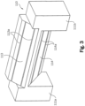
- Fig. 3 exemplarily shows a schematic perspective view of the machine frame 110 of the machine tool 100 of Fig. 2 .
- the machine frame 110 depicted in the figure stands on two machine stand portions 111a and 111b, and a carrier support portion of the machine frame 110 is formed in between and held by the machine stand portions 111a and 111b.
- the depicted machine frame 110 includes the upper tool carrier support portion 113 and a lower tool carrier support portion 114, both of which horizontally extending between the two machine stand portions 111a and 111b.
- the upper side surface of the upper tool carrier support portion 113 of the machine frame 110 is arranged at an inclined slope, and the lower side surface of the lower tool carrier support portion 114 of the machine frame 110 is arranged at an overhanging inclined slope.
- the upper tool carrier support portion 113 of the machine frame 110 has horizontally extending guides 113a. Accordingly, for slidably supporting the tool carrier assemblies 150c, 150d on the lower side of the machine frame 110 in a machining area of the machine tool 100, the lower tool carrier support portion 114 of the machine frame 110 has horizontally extending guides 114a.
- a tool support slide 152 is slidably mounted to the carrier support slide 151.
- the tool support slide 152 is configured to be moved vertically on and along vertical guides arranged on a front face of the carrier support slide 151 in the X-axis direction.
- the degrees of freedom in terms of the linear and rotational movement of the work spindles 200a, 200b and milling units 201a, 201b described in connection with Fig. 1 can be realized.
- the tool support slide 152 of the first tool carrier assembly 150a can be moved downward in the X-axis direction on the vertical guides of the carrier support slide 151, e.g., until it reaches its lowest position.
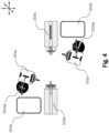
- Fig. 4 exemplarily shows an arrangement of work spindles and milling units according to another exemplary embodiment of the invention.
- the depicted arrangement differs from that shown in Fig. 1 by comprising a first and a second work spindle 200a, 200b being movable only in the Z-axis direction
- the first work spindle 200a depicted on the left side of Fig. 4 may serve as a main spindle and the second work spindle 200b depicted on the right side of Fig. 4 may serve as a counter spindle.
- B-axes 201aa, 201ba of the first and second milling units 201a, 201b are arranged so as to not intersect with a rotation axis of the respective milling unit 201a, 201b (i.e. eccentric arrangement of the milling units; preferably only the lower installed milling unit is eccentric arranged, for improved accessibility and keeping the machine axis or machining axis od th spindle closer to the workshop floor). Therefore, each of the first and the second milling units 201a, 201b may rotate about the corresponding B-axis 201aa, 201ba on a radius r distant from the latter.
- each milling unit 201a, 201b about its B axis 201aa, 201ba simultaneously moves the latter in the direction of the X axis as described below in connection with Figs. 7a and 7b .
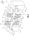
- Fig. 5 exemplarily shows a machine tool 100 on which the arrangement of spindles and milling depicted in Fig. 4 can be applied
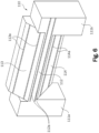
- Fig. 6 exemplarily shows a schematic perspective view of its machine frame 110.
- the depicted machine tool 100 is identical to the machine tool 100 shown in Fig. 2 except that the machine frame 110 includes a spindle support portion 112, formed at its front between the upper support portion 113 and the lower support portion 114, which extends horizontally between the two machine stand portions 111a and 111b.
- a main spindle carrier 120 carrying a main spindle 200a On/at the spindle support portion 112 a main spindle carrier 120 carrying a main spindle 200a, a counter spindle carrier 140 carrying a counter spindle 200b and an auxiliary spindle carrier 130 carrying an auxiliary spindle 131 are arranged.
- the spindle support portion 112 has a vertically arranged front surface, on which horizontally extending guides 112a are applied for slidably supporting the auxiliary spindle carrier 130 and the counter spindle carrier 140 in the Z-axis direction.
- the workpiece-carrying main spindle 200a supported by the main spindle carrier 120 is configured to receive an elongated workpiece, such as a bar, and drive a rotation of the received workpiece around the spindle axis of the main spindle 200a.
- the main spindle 200a is arranged with its spindle axis extending in the horizontal direction (Z-axis direction).
- the counter-spindle carrier 140 may be slidably mounted to the spindle support portion 112 on the guides 112a.
- the machine frame 110 carries the counter-spindle carrier 140 which includes the workpiece-carrying counter spindle 200b being configured to receive an elongated workpiece, such as a bar, and drive a rotation of the received workpiece around the spindle axis of the counter spindle 200b.
- the counter spindle 200b is arranged with its spindle axis extending in the horizontal direction (Z-axis direction).
- the counter spindle 200b is arranged opposing the main spindle 200a with its spindle axis extending in the horizontal direction coaxially arranged with respect to the spindle axis of the main spindle 200a. Accordingly, the counter spindle 200b can be moved horizontally towards the main spindle 200a to receive the workpiece received in the main spindle 200a to take over the workpiece from the main spindle 200a, e.g. for allowing to machine the rear ends of the workpiece.
- an optional auxiliary spindle carrier 130 is slidably mounted to the spindle support portion 112 between the main spindle carrier 120 and the counter-spindle carrier 140, guided horizontally on the guides 112a on the spindle support portion 112, i.e. on the same guides 112a which support the counter spindle carried 130.
- the machine frame 110 carries the optional auxiliary spindle carrier 130 which includes (or at least supports) an auxiliary spindle 131 being configured to receive an elongated workpiece, such as a bar, and support and/or guide a rotation of the received workpiece around the guide rotation axis of the auxiliary spindle 131.
- the auxiliary spindle 131 is arranged with its guide rotation axis (auxiliary spindle axis) extending in the horizontal direction (Z-axis direction).
- the auxiliary spindle 131 can act as a spindle that clamps/holds a workpiece and drives rotation of the workpiece and can also act as a rotary guide bush that guides rotation of a workpiece clamped in one of or both of the main and counter spindles.
- the auxiliary spindle 131 can be moved horizontally in the range in between the main spindle 200a and the counter spindle 200b to take over the workpiece received in the main spindle 200a, to guide and/or support it, e.g. to prevent bending of the workpiece due to a force applied by the tool or to receive the workpiece received in the counter spindle 200b and to guide and/or support it, e.g. to prevent bending of the workpiece due to a force applied by the tool.
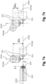
- Fig. 7a and 7b exemplary show a comparison between a required traverse path in X-axis direction of a conventional milling unit and the milling unit shown in Fig. 4 .
- Fig. 7a depicts a horizontally arranged work spindle 200 with a workpiece 203 whose spindle axis 2000 extends in Z-axis direction.
- a milling tool 201 is disposed relative to the work spindle 200a, 200b in a first and a second position, wherein the first position is indicated by depicting the milling unit 201 in solid lines and the second position by depicting the milling unit 201 in dotted lines.
- the milling unit 200 depicted in Fig. 7a has a B-axis 201aa that intersects with a rotation axis 2010 of the milling unit 201.
- the milling unit 201 In the first position, the milling unit 201 is arranged perpendicular to the work spindle 200, which means that its rotation axis 2010 extends in X-axis direction.
- the first position may be used to machine an outer surface of the workpiece by the milling unit 201.
- the milling unit 201 is arranged coaxial to the work spindle 200, which means that its rotation axis 2010 extends in Z-axis direction along the same axis as that of the work spindle 200.
- the second position may be used to machine a front end of the workpiece by the milling unit 201.
- the latter has to be rotated by 90 degrees and moved linearly in X-axis direction by a distance ⁇ x 1 .
- Fig. 7b depicts a milling unit 201 having a B-axis 201aa that does not intersect with a rotation axis 2010 of the milling unit 201.
- the B-axis is arranged a predetermined distance apart from the rotation axis 2010 of the milling unit 201, which means that the milling unit 201 rotates about the B-axis 201aa on a radius r having the predetermined distance to the rotation axis 2010 of the milling unit 201.
- the milling unit 201 may first rotate about the B-axis 201aa by 90 degrees.
- the milling unit 201 is already moved in X-axis direction by a certain distance.
- the additional distance ⁇ x 2 by which the milling unit 201 has to be moved in X-axis direction to reach the second position is shorter than the distance ⁇ x 1 .
- a traverse path of the milling tool 201 in X-axis direction e.g., that of the tool support slide 152 shown in Fig. 5 , can be shortened, in order to provide a compact machine tool 100.
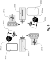
- Fig. 8 exemplarily shows an arrangement of work spindles and milling units according to yet one another exemplary embodiment of the invention.
- the depicted arrangement differs from that shown in Fig. 4 by comprising two additional turrets 204a, 204b.
- a first turret 204a is arranged above the second work spindle 200b depicted on the right side of Fig. 8 , wherein the second work spindle 200b may serve as a counter spindle.
- a second turret 204b is arranged below the first work spindle 200b depicted on the left side of Fig. 8 , wherein the first work spindle 200b may serve as a main spindle.
- the first and second turrets 204a, 204b may be equipped with a plurality of different tools such as drills, milling cutters, chisels etc..
- the additional turrets 204a, 204b allow to perform additional machining steps in one machining pass, so that the efficiency of the machine tool 100 can be further improved.
- Fig. 8 The arrangement of work spindles, milling tools and turrets shown in Fig. 8 can be applied to the machine unit 100 of Fig.5 which provides a spindle support portion 112 with specific spindle carriers 120, 130, 140 for accommodating the work spindles 200a, 200b, 131.
- the tool carrier assemblies 150a - 150d of the upper and lower tool carrier portions 113, 114 are reserved for the first and the second milling units 201a, 201b and the additional turrets 204a, 204b supporting the latter.
Landscapes
- Engineering & Computer Science (AREA)
- Mechanical Engineering (AREA)
- Machine Tool Units (AREA)
- Turning (AREA)
Priority Applications (4)
| Application Number | Priority Date | Filing Date | Title |
|---|---|---|---|
| EP23162634.2A EP4431230A1 (fr) | 2023-03-17 | 2023-03-17 | Machine-outil, en particulier tour, et procédé d'usinage de pièces à l'aide d'une machine-outil |
| JP2024024821A JP2024132911A (ja) | 2023-03-17 | 2024-02-21 | 工作機械、特に旋盤、および工作機械を用いたワーク加工方法 |
| US18/605,631 US20240307971A1 (en) | 2023-03-17 | 2024-03-14 | Machine tool, in particular a lathe, and method for machining workpieces using a machine tool |
| CN202410304874.XA CN118663953A (zh) | 2023-03-17 | 2024-03-18 | 机床、特别是车床以及使用机床加工工件的方法 |
Applications Claiming Priority (1)
| Application Number | Priority Date | Filing Date | Title |
|---|---|---|---|
| EP23162634.2A EP4431230A1 (fr) | 2023-03-17 | 2023-03-17 | Machine-outil, en particulier tour, et procédé d'usinage de pièces à l'aide d'une machine-outil |
Publications (1)
| Publication Number | Publication Date |
|---|---|
| EP4431230A1 true EP4431230A1 (fr) | 2024-09-18 |
Family
ID=85704709
Family Applications (1)
| Application Number | Title | Priority Date | Filing Date |
|---|---|---|---|
| EP23162634.2A Pending EP4431230A1 (fr) | 2023-03-17 | 2023-03-17 | Machine-outil, en particulier tour, et procédé d'usinage de pièces à l'aide d'une machine-outil |
Country Status (4)
| Country | Link |
|---|---|
| US (1) | US20240307971A1 (fr) |
| EP (1) | EP4431230A1 (fr) |
| JP (1) | JP2024132911A (fr) |
| CN (1) | CN118663953A (fr) |
Citations (3)
| Publication number | Priority date | Publication date | Assignee | Title |
|---|---|---|---|---|
| WO2000054930A2 (fr) * | 1999-03-15 | 2000-09-21 | Boehringer Werkzeugmaschinen Gmbh | Machine-outil |
| EP3616832A1 (fr) | 2018-08-29 | 2020-03-04 | Gildemeister Italiana S.p.A. | Machine-outil, notamment un tour |
| EP3871834A1 (fr) * | 2020-02-28 | 2021-09-01 | Gildemeister Italiana S.r.l. | Machine-outil, notamment un tour comportant une broche auxiliaire |
-
2023
- 2023-03-17 EP EP23162634.2A patent/EP4431230A1/fr active Pending
-
2024
- 2024-02-21 JP JP2024024821A patent/JP2024132911A/ja active Pending
- 2024-03-14 US US18/605,631 patent/US20240307971A1/en active Pending
- 2024-03-18 CN CN202410304874.XA patent/CN118663953A/zh active Pending
Patent Citations (3)
| Publication number | Priority date | Publication date | Assignee | Title |
|---|---|---|---|---|
| WO2000054930A2 (fr) * | 1999-03-15 | 2000-09-21 | Boehringer Werkzeugmaschinen Gmbh | Machine-outil |
| EP3616832A1 (fr) | 2018-08-29 | 2020-03-04 | Gildemeister Italiana S.p.A. | Machine-outil, notamment un tour |
| EP3871834A1 (fr) * | 2020-02-28 | 2021-09-01 | Gildemeister Italiana S.r.l. | Machine-outil, notamment un tour comportant une broche auxiliaire |
Also Published As
| Publication number | Publication date |
|---|---|
| JP2024132911A (ja) | 2024-10-01 |
| US20240307971A1 (en) | 2024-09-19 |
| CN118663953A (zh) | 2024-09-20 |
Similar Documents
| Publication | Publication Date | Title |
|---|---|---|
| US11167354B2 (en) | Machine tool, in particular lathe | |
| US9914189B2 (en) | Machine tool having a workpiece changing device | |
| US10207381B2 (en) | Machine tool having a number of multispindle spindle assemblies | |
| US6715386B2 (en) | Turning method | |
| US9126266B2 (en) | Machine tool | |
| US9156119B2 (en) | Machine tool | |
| US8529420B2 (en) | Machine tool for processing workpieces | |
| CN103747899B (zh) | 机床 | |
| CN103747900B (zh) | 刀具支架和具有刀具支架的机床 | |
| US7101129B2 (en) | Machine tool | |
| US12564886B2 (en) | Machine tool, in particular lathe with auxiliary spindle | |
| CN101434033A (zh) | 多主轴加工中心 | |
| US20240307971A1 (en) | Machine tool, in particular a lathe, and method for machining workpieces using a machine tool | |
| CN214642458U (zh) | 一种小型工件加工磨床 | |
| US6484611B1 (en) | Lathe | |
| JP2007075922A (ja) | 複合旋盤 | |
| CN112454074A (zh) | 一种小型工件加工磨床 | |
| JP7568102B2 (ja) | 対向二軸型旋盤 | |
| CN112355664A (zh) | 一种小型工件加工机床 | |
| JP2006123046A (ja) | 旋盤 |
Legal Events
| Date | Code | Title | Description |
|---|---|---|---|
| PUAI | Public reference made under article 153(3) epc to a published international application that has entered the european phase |
Free format text: ORIGINAL CODE: 0009012 |
|
| STAA | Information on the status of an ep patent application or granted ep patent |
Free format text: STATUS: THE APPLICATION HAS BEEN PUBLISHED |
|
| AK | Designated contracting states |
Kind code of ref document: A1 Designated state(s): AL AT BE BG CH CY CZ DE DK EE ES FI FR GB GR HR HU IE IS IT LI LT LU LV MC ME MK MT NL NO PL PT RO RS SE SI SK SM TR |
|
| STAA | Information on the status of an ep patent application or granted ep patent |
Free format text: STATUS: REQUEST FOR EXAMINATION WAS MADE |
|
| 17P | Request for examination filed |
Effective date: 20250124 |
|
| STAA | Information on the status of an ep patent application or granted ep patent |
Free format text: STATUS: EXAMINATION IS IN PROGRESS |