EP4431321A1 - Fenster mit entlüftungsfensteranordnung für ein fahrzeug - Google Patents
Fenster mit entlüftungsfensteranordnung für ein fahrzeug Download PDFInfo
- Publication number
- EP4431321A1 EP4431321A1 EP23315051.5A EP23315051A EP4431321A1 EP 4431321 A1 EP4431321 A1 EP 4431321A1 EP 23315051 A EP23315051 A EP 23315051A EP 4431321 A1 EP4431321 A1 EP 4431321A1
- Authority
- EP
- European Patent Office
- Prior art keywords
- vent window
- window
- vent
- assembly
- frame assembly
- Prior art date
- Legal status (The legal status is an assumption and is not a legal conclusion. Google has not performed a legal analysis and makes no representation as to the accuracy of the status listed.)
- Pending
Links
Images



Classifications
-
- B—PERFORMING OPERATIONS; TRANSPORTING
- B60—VEHICLES IN GENERAL
- B60J—WINDOWS, WINDSCREENS, NON-FIXED ROOFS, DOORS, OR SIMILAR DEVICES FOR VEHICLES; REMOVABLE EXTERNAL PROTECTIVE COVERINGS SPECIALLY ADAPTED FOR VEHICLES
- B60J1/00—Windows; Windscreens; Accessories therefor
- B60J1/08—Windows; Windscreens; Accessories therefor arranged at vehicle sides
- B60J1/12—Windows; Windscreens; Accessories therefor arranged at vehicle sides adjustable
- B60J1/16—Windows; Windscreens; Accessories therefor arranged at vehicle sides adjustable slidable
-
- B—PERFORMING OPERATIONS; TRANSPORTING
- B64—AIRCRAFT; AVIATION; COSMONAUTICS
- B64C—AEROPLANES; HELICOPTERS
- B64C27/00—Rotorcraft; Rotors peculiar thereto
- B64C27/04—Helicopters
-
- B—PERFORMING OPERATIONS; TRANSPORTING
- B64—AIRCRAFT; AVIATION; COSMONAUTICS
- B64C—AEROPLANES; HELICOPTERS
- B64C1/00—Fuselages; Constructional features common to fuselages, wings, stabilising surfaces or the like
- B64C1/14—Windows; Doors; Hatch covers or access panels; Surrounding frame structures; Canopies; Windscreens accessories therefor, e.g. pressure sensors, water deflectors, hinges, seals, handles, latches, windscreen wipers
- B64C1/1476—Canopies; Windscreens or similar transparent elements
- B64C1/1492—Structure and mounting of the transparent elements in the window or windscreen
-
- B—PERFORMING OPERATIONS; TRANSPORTING
- B64—AIRCRAFT; AVIATION; COSMONAUTICS
- B64D—EQUIPMENT FOR FITTING IN OR TO AIRCRAFT; FLIGHT SUITS; PARACHUTES; ARRANGEMENT OR MOUNTING OF POWER PLANTS OR PROPULSION TRANSMISSIONS IN AIRCRAFT
- B64D13/00—Arrangements or adaptations of air-treatment apparatus for aircraft crew or passengers, or freight space
-
- B—PERFORMING OPERATIONS; TRANSPORTING
- B60—VEHICLES IN GENERAL
- B60J—WINDOWS, WINDSCREENS, NON-FIXED ROOFS, DOORS, OR SIMILAR DEVICES FOR VEHICLES; REMOVABLE EXTERNAL PROTECTIVE COVERINGS SPECIALLY ADAPTED FOR VEHICLES
- B60J1/00—Windows; Windscreens; Accessories therefor
- B60J1/004—Mounting of windows
- B60J1/007—Mounting of windows received in frames to be attached to vehicle
-
- B—PERFORMING OPERATIONS; TRANSPORTING
- B60—VEHICLES IN GENERAL
- B60J—WINDOWS, WINDSCREENS, NON-FIXED ROOFS, DOORS, OR SIMILAR DEVICES FOR VEHICLES; REMOVABLE EXTERNAL PROTECTIVE COVERINGS SPECIALLY ADAPTED FOR VEHICLES
- B60J1/00—Windows; Windscreens; Accessories therefor
- B60J1/18—Windows; Windscreens; Accessories therefor arranged at the vehicle rear
- B60J1/1838—Windows; Windscreens; Accessories therefor arranged at the vehicle rear movable for non-convertible vehicles, including vehicles with versatile load area
- B60J1/1846—Windows; Windscreens; Accessories therefor arranged at the vehicle rear movable for non-convertible vehicles, including vehicles with versatile load area where the window can slide
- B60J1/1853—Windows; Windscreens; Accessories therefor arranged at the vehicle rear movable for non-convertible vehicles, including vehicles with versatile load area where the window can slide horizontally in direction transverse to vehicle longitudinal axis
Definitions
- the invention is related to a window for a vehicle comprising a main window pane with a vent window opening, and a vent window assembly that is mounted to the main window pane.
- the invention is further related to a vehicle which comprises a window with a vent window assembly.
- Vent window assemblies may be provided in windows of a variety of different vehicles, such as cars, trucks, trains, ships, aircrafts and so on.
- vehicles such as cars, trucks, trains, ships, aircrafts and so on.
- the documents EP 3 137 325 A1 and US 2004/0134131 A1 describe windows with vent window assemblies.
- vent window assemblies are integrated into windows which may not be opened as such so that, nevertheless, venting is enabled through the vent window assemblies.
- respective vent window assemblies which are e. g. provided in windows of aircraft cockpit windows may be opened during poor weather conditions or stormy weather in order to avoid misting of the aircraft cockpit windows.
- vent window assemblies may be opened in case of difficult flight conditions to allow a respective flight crew to retrieve a visual reference point.
- vent window assemblies which may also be referred to as "bad weather windows” or “storm windows” are usually mandatory features in aircrafts, at least in aircraft cockpits. They are generally arranged at suitable openings provided in main window panes of windows and associated opening/closing mechanisms are either screwed/bolted or adhesively bonded to the main window panes.
- a plurality of holes is drilled in the main window pane at predetermined positions around a respective vent window opening and the vent window assembly is maintained in the respective vent window opening by means of screws and/or bolts passing through the drilled holes formed in the main window pane.
- the main window pane as such is generally made out of acrylic so that sooner or later a crack will appear starting from one of the drill holes due to a combination of stress concentration, aging and repeated flight loads. This phenomenon can be postponed by design or assembly improvements, but can generally not be avoided entirely.
- associated vent window frames are held at the respective vent window opening of the main window pane by means of an adhesive.
- flight loads are continuously and homogeneously transmitted between the main window pane and the vent window assembly.
- a respectively required bonding process involves specifically trained operators, which does not allow for easy and quick field replacement in case of an issue.
- structural bonding may be complex to develop and require specific provisions to ensure a satisfactory life cycle, which may impact cost, perceived quality, etc.
- an object of the present invention to provide a new window with a vent window assembly that is suitable to overcome the above-described drawbacks and problems of the state-of-the-art.
- a window for a vehicle comprising a main window pane with a vent window opening, and a vent window assembly that is mounted to the main window pane.
- the vent window assembly comprises a movable vent window pane that is adapted for closing the vent window opening in a closed state of the vent window assembly, a first vent window frame assembly comprising a first support frame that is arranged on a first surface of the main window pane, and a second vent window frame assembly comprising a second support frame that is arranged on a second surface of the main window pane.
- the second vent window frame assembly is rigidly attached to the first vent window frame assembly at the vent window opening such that the first and second vent window frame assemblies fasten each other at the main window pane.
- the main window pane supports the vent window assembly.
- the vent window assembly comprises two main components: the first vent window frame assembly and the second vent window frame assembly, which are fastened to each other, e. g. clipped into each other via a clip connection, or clamped at each other via a clamp connection, and so on.
- Either the first vent window frame assembly or the second vent window frame assembly may form guide rails in which the movable vent window pane may glide.
- the movable vent window pane may be hinged to one of the first vent window frame assembly or the second vent window frame assembly.
- the inventive vent window assembly may be fully transparent, or at least translucent. Furthermore, by rigidly attaching the first vent window frame only to the second vent window frame at the vent window opening, both are maintained at the vent window opening without a need for mechanically-loaded drill holes in the main window pane, as conventionally required when using fasteners such as screws or bolts. Thus, stress-concentration-induced cracks around drill holes, as may be observed on fastened vent window assemblies, may be avoided. Likewise, due to an absence of structurally-bonded connections between the vent window assembly and the main window pane adhesive failures may be avoided.
- an overall stiffness of the assembly can be tuned by a suitable design of respectively used fastening means, such as clips or clamps, in particular to control vibrations.
- the main window pane may even be a double curvature-shaped main window.
- any clips or clamps used to fasten the vent window assembly at the main window pane i. e. to attach the first vent window frame assembly to the second vent window frame assembly
- the clips or clamps may be provided at specific locations only, i. e. in a punctiform manner, or they may be provided as continuous or surrounding elements all along the first vent window frame assembly and the second vent window frame assembly.
- an underlying weight of the vent window assembly can be reduced by design optimization in order to be competitive with other assemblies.
- Another advantage is that the vent window assembly is compatible with existing drainage systems, as well as with spoiler designs, in particular to achieve lower noise/vibration levels and an increase of water tightness.
- suitable rubber or foam layers may be provided on associated contact surfaces formed between the main window pane and the first vent window frame assembly, as well as between the main window pane and the second vent window frame assembly.
- suitable rubber or foam layers also prevent hard contact surfaces and reduce vibrations between the main window pane and the first vent window frame assembly, as well as between the main window pane and the second vent window frame assembly.
- the first vent window frame assembly is rigidly attached to the second vent window frame assembly through one of a press fit connection, a snap-lock connection, or a clip connection.
- the first vent window frame assembly comprises at least one fastener
- the second vent window frame assembly comprises at least one retaining element adapted for retaining the at least one fastener
- the at least one fastener may comprise a locking pin
- the at least one retaining element may comprise a locking pin snap-in counterpart.
- the vent window assembly comprises a guide rail assembly that accommodates the movable vent window pane glidingly.
- the guide rail assembly may be integrated into one of the first or second vent window frame assemblies.
- the movable vent window pane may be mounted pivotally to one of the first or second vent window frame assemblies.
- the vent window assembly comprises at least one sealing element arranged between the first support frame of the first vent window frame assembly and the first surface of the main window pane.
- the at least one sealing element may comprise a rubber layer and/or a foam layer.
- the vent window assembly comprises at least one other sealing element arranged between the second support frame of the second vent window frame assembly and the second surface of the main window pane.
- the at least one other sealing element may comprise a rubber layer and/or a foam layer.
- the second vent window frame assembly is detachably mounted to the first vent window frame assembly at the vent window opening.
- the second vent window frame assembly may be permanently locked to the first vent window frame assembly at the vent window opening.
- the present invention relates further to a vehicle comprising a window with a vent window assembly as described above.
- the vehicle may be embodied as an aircraft, in particular a rotorcraft, wherein the window is one of a cockpit window or a cabin side window.
- FIG. 1 shows an aircraft 1 that is illustratively embodied as a rotorcraft and, more particularly, as a helicopter.
- helicopter 1 the aircraft 1
- the present invention is, however, not limited to helicopters and may likewise be applied to any other aircraft and, more generally, to any other vehicle, such as a car, a truck, a train, a ship, and so on.
- the helicopter 1 comprises at least one main rotor 1a, preferably a multi-blade main rotor, for providing lift and forward or backward thrust during operation.
- the at least one main rotor 1a comprises a plurality of rotor blades which are connected at an associated rotor head 1d to a rotor shaft 1e, which rotates in operation of the helicopter 1 about an associated rotor axis.
- Two rotor blades of the plurality of rotor blades are illustratively separately labelled with the reference signs 1b, 1c.
- the helicopter 1 comprises a fuselage 2.
- a left-hand side of the fuselage 2 is shown and, thus, a portside wall of the fuselage 2 of the helicopter 1, to which a landing gear 1f of the skid-type is attached.
- the fuselage 2 forms an aircraft interior region that accommodates a cockpit 2a and that may further accommodate a cabin 2c for passengers and/or cargo.
- the cockpit 2a is provided with at least one window 6 that comprises a main window pane 6a to which a vent window assembly 7 with a movable vent window pane 7a is mounted, as described below at Figure 2 to Figure 5 .
- the at least one window 6 is a cockpit door main window.
- the cabin 2c is also provided with at least one window 2d that forms a cabin side window and that may also be provided with the vent window assembly 7.
- the fuselage 2 of the helicopter 1 is connected at a rear fuselage 2b to a tail boom 3 with a horizontal stabilizer 3a.
- the tail boom 3 may be implemented as a slim beam element that comprises at least a tubular tail boom cone 3b.
- the helicopter 1 illustratively further comprises at least one preferentially shrouded counter-torque device 4 configured to provide counter-torque during operation, i. e. to counter the torque created by rotation of the at least one main rotor 1a for purposes of balancing the helicopter 1 in terms of yaw.
- the at least one counter-torque device 4 is illustratively provided at an aft section of the tail boom 3 and preferably comprises a tail rotor 4a.
- the aft section of the tail boom 3 preferably further comprises a fin 5.
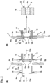
- FIG 2 shows in part (A) and part (B) the window 6 comprising the main window pane 6a according to Figure 1 with the vent window assembly 7 comprising the movable vent window pane 7a according to Figure 1 .
- the main window pane 6a comprises a vent window opening 6b that is equipped with the vent window assembly 7.
- the movable vent window pane 7a is adapted for closing the vent window opening 6b in a closed state of the vent window assembly 7.
- the vent window assembly 7 comprises at least a first vent window frame assembly 8 and a second vent window frame assembly 10.
- the first vent window frame assembly 8 comprises a first support frame 8a that is arranged on a first surface 6c of the main window pane 6a.
- the first surface 6c forms an outer surface of the main window pane 6a and, likewise, the first vent window frame assembly 8 forms an outer vent window frame assembly and the first support frame 8a forms an outer support frame.
- the second vent window frame assembly 10 comprises a second support frame 10a that is arranged on a second surface 6d of the main window pane 6a.
- the second surface 6d forms an inner surface of the main window pane 6a and, likewise, the second vent window frame assembly 10 forms an inner vent window frame assembly and the second support frame 10a forms an inner support frame.
- the inner vent window frame assembly 10 is rigidly attached to the outer vent window frame assembly 8 at the vent window opening 6b such that the outer and inner vent window frame assemblies 8, 10 fasten each other at the main window pane 6a.
- the outer vent window frame assembly 8 comprises at least one fastener 9 and the inner vent window frame assembly 10 may comprise at least one retaining element 11 adapted for retaining the at least one fastener 9.
- the at least one fastener 9 may comprise one or more locking pins and the at least one retaining element 11 may comprise one or more locking pin snap-in counterparts.
- the one or more locking pins 9 may be toothed rods 9a and the one or more locking pin snap-in counterparts 11 may be toothed sleeves 11a.
- the locking pins 9 and the locking pin snap-in counterparts 11 may be provided only at specific locations of the vent window assembly 7, i. e. in a punctiform manner, or they may be provided as continuous or surrounding elements all along the outer vent window frame assembly 8 and the inner vent window frame assembly 10.
- the vent window assembly 7 comprises a guide rail assembly 12 that accommodates the movable vent window pane 7a glidingly.
- the guide rail assembly 12 may comprise an upper guide rail 12a and a lower guide rail 12b for accommodating the movable vent window pane 7a glidingly.
- the inner vent window frame assembly 10 embodies the guide rail assembly 12.
- the outer vent window frame assembly 8 may be equipped with a spoiler 8b.
- the vent window assembly 7 may be equipped with at least one sealing element 13a, 13b arranged between the outer support frame 8a of the outer vent window frame assembly 8 and the outer surface 6c of the main window pane 6a.
- the vent window assembly 7 may be equipped with at least one other sealing element 14a, 14b arranged between the inner support frame 10a of the inner vent window frame assembly 10 and the inner surface 6d of the main window pane 6a.
- Each one of the sealing elements 13a, 13b, 14a, 14b may comprise a rubber layer and/or a foam layer.
- part (A) and part (B) of Figure 2 show an illustrative mounting process of the vent window assembly 7 to the main window pane 6a of the window 6, wherein the movable vent window pane 7a is mounted to its closed position in the closed state of the vent window assembly 7.
- the vent window assembly 7 is shown at the main window pane 6a of the window 6 in disassembled state and in part (B) in assembled state.
- the outer vent window frame assembly 8 with the outer support frame 8a is initially arranged at the vent window opening 6b close to the outer surface 6c of the main window pane 6a and the inner vent window frame assembly 10 is initially arranged at the vent window opening 6b close to the inner surface 6d of the main window pane 6a.
- the outer support frame 8a is arranged at the vent window opening 6b such that the one or more locking pins 9 point toward the vent window opening 6b.
- the movable vent window pane 7a is illustratively accommodated in the guide rail assembly 12 and the inner support frame 10a is arranged at the vent window opening 6b such that the movable vent window pane 7a points toward the vent window opening 6b. Then, the outer vent window frame assembly 8 is pushed toward the vent window opening 6b, as illustrated with an arrow 15a, and the inner vent window frame assembly 10 is pushed toward the vent window opening 6b, as illustrated with an arrow 15b.
- the outer vent window frame assembly 8 was pushed toward the vent window opening 6b, as illustrated with the arrow 15a, and the inner vent window frame assembly 10 was pushed toward the vent window opening 6b, as illustrated with the arrow 15b, such that the one or more locking pins 9 traversed the vent window opening 6b and engaged with the one or more locking pin snap-in counterparts 11.
- the inner vent window frame assembly 10 is rigidly attached to the outer vent window frame assembly 8 at the vent window opening 6b by the engagement of the one or more locking pins 9 with the one or more locking pin snap-in counterparts 11.
- the inner vent window frame assembly 10 is thereby permanently locked to the outer vent window frame assembly 8 at the vent window opening 6b.
- sealing elements 13a, 13b, 14a, 14b are omitted in part (B). However, this is only for simplicity and clarity and not for limiting the invention accordingly.
- FIG 3 shows in part (A) and part (B) the window 6 comprising the main window pane 6a according to Figure 2 with the vent window assembly 7 comprising the movable vent window pane 7a of Figure 2 .
- the vent window assembly 7 comprises the outer vent window frame assembly 8 and the inner vent window frame assembly 10.
- part (A) is a cut view seen along a cut line 17 in part (B), which is a lateral view of the window 6 with the vent window assembly 7.
- part (A) only illustrates the guide rail assembly 12 with the movable vent window pane 7a, as well as a permanently closing vent window pane 7b of the vent window assembly 7.
- the main window pane 6a comprises the vent window opening 6b that is equipped with the vent window assembly 7.
- the vent window assembly 7 is shown in the closed state and a cut line II-II is drawn along which the cut view of Figure 2 as described above is shown.
- the movable vent window pane 7a closes the vent window opening 6b.
- the movable vent window pane 7a actually only closes a part of the vent window opening 6b in the closed state, whereas the remaining part is permanently closed by means of the permanently closing vent window pane 7b.
- the latter is preferably rigidly mounted to the main window pane 6a using the outer vent window frame assembly 8 and the inner vent window frame assembly 10, as described below at Figure 4 .
- Figure 3 illustrates further to Figure 2 upper and lower guide rail extensions 12c, 12d of the guide rail assembly 12 of Figure 2 .
- These guide rail extensions 12c, 12d illustratively extend on, i. e. along the inner surface 6d of the main window pane 6a. They are required to enable gliding movement of the movable vent window pane 7a from an illustrated closed position to an opened position illustrated in Figure 4 and Figure 5 .
- FIG 4 shows in part (A) and part (B) the window 6 comprising the main window pane 6a according to Figure 2 and Figure 3 with the vent window assembly 7 comprising the movable vent window pane 7a of Figure 2 and Figure 3 , as well as the permanently closing vent window pane 7b of Figure 3 .
- the main window pane 6a comprises the vent window opening 6b that is equipped with the vent window assembly 7.
- the vent window assembly 7 is now shown in opened state. Accordingly, the part of the vent window opening 6b that is closed by the movable vent window pane 7a in closed state of the vent window assembly 7 is now open.
- the vent window assembly 7 comprises the outer vent window frame assembly 8 with the outer support frame 8a and the inner vent window frame assembly 10 with the inner support frame 10a.
- the inner vent window frame assembly 10 comprises the upper and lower guide rail extensions 12c, 12d of the guide rail assembly 12 of Figure 2 and Figure 3 , which extend on and along the inner surface 6d of the main window pane 6a.
- Figure 4 also shows additional upper and lower accommodations 12e, 12f for accommodating the permanently closing vent window pane 7b.
- the upper and lower accommodations 12e, 12f are illustratively formed by the outer support frame 8a and the inner support frame 10a.
- the upper and lower accommodations 12e, 12f may be equipped with suitable sealing elements.
- the sealing elements may be arranged between the permanently closing vent window pane 7b and the outer and inner support frames 8a, 10a. They may comprise rubber layers and/or foam layers.
- part (A) and part (B) of Figure 4 show an illustrative mounting process of the vent window assembly 7 to the main window pane 6a of the window 6.
- the vent window assembly 7 is shown at the main window pane 6a of the window 6 in disassembled state and in part (B) in assembled state.
- the movable vent window pane 7a is mounted to its opened position in the opened state of the vent window assembly 7.
- the outer vent window frame assembly 8 with the outer support frame 8a is initially arranged at the vent window opening 6b close to the outer surface 6c of the main window pane 6a and the inner vent window frame assembly 10 is initially arranged at the vent window opening 6b close to the inner surface 6d of the main window pane 6a.
- the movable vent window pane 7a is accommodated in the upper and lower guide rail extensions 12c, 12d of the guide rail assembly 12 and the inner support frame 10a is arranged at the vent window opening 6b such that the movable vent window pane 7a points toward the vent window opening 6b.
- the permanently closing vent window pane 7b is arranged between the outer support frame 8a and the inner support frame 10a.
- the outer vent window frame assembly 8 was pushed toward the vent window opening 6b, as illustrated with the arrow 15a, and the inner vent window frame assembly 10 was pushed toward the vent window opening 6b, as illustrated with the arrow 15b, such that the inner vent window frame assembly 10 is rigidly attached to the outer vent window frame assembly 8 at the vent window opening 6b, as described above at Figure 2 .
- the upper and lower accommodations 12e, 12f are formed and the permanently closing vent window pane 7b is rigidly mounted therein.
- FIG 5 shows in part (A) and part (B) the window 6 comprising the main window pane 6a according to Figure 4 with the vent window assembly 7 comprising the movable vent window pane 7a and the permanently closing vent window pane 7b of Figure 4 .
- the vent window assembly 7 comprises the outer vent window frame assembly 8 and the inner vent window frame assembly 10.
- part (A) is a cut view seen along a cut line 18 in part (B), which is a lateral view of the window 6 with the vent window assembly 7.
- part (A) only illustrates the guide rail assembly 12 with the movable vent window pane 7a, as well as the permanently closing vent window pane 7b of the vent window assembly 7.
- the main window pane 6a comprises the vent window opening 6b that is equipped with the vent window assembly 7.
- the vent window assembly 7 is shown in the opened state and a cut line IV-IV is drawn along which the cut view of Figure 4 as described above is shown.
- the movable vent window pane 7a is preferably glidingly accommodated in the guide rail assembly 12.
- the movable vent window pane 7a may alternatively be mounted pivotally to one of the outer or inner vent window frame assemblies 8, 10.
- the inner vent window frame assembly 10 is preferably permanently locked to the outer vent window frame assembly 8 at the vent window opening 6b. Nevertheless, the inner vent window frame assembly 10 may alternatively be mounted detachably to the outer vent window frame assembly 8 at the vent window opening 6b.
- the guide rail assembly 12 is preferably integrated into the inner vent window frame assembly 10.
- the guide rail assembly 12 may alternatively be integrated into the outer vent window frame assembly 8.
- the outer vent window frame assembly 8 is rigidly attached to the inner vent window frame assembly 10 through a snap-lock connection.
- any other suitable type of connection such as a cramp connection, a press fit connection, a clip connection or others is likewise contemplated.
Landscapes
- Engineering & Computer Science (AREA)
- Aviation & Aerospace Engineering (AREA)
- Mechanical Engineering (AREA)
- Health & Medical Sciences (AREA)
- General Health & Medical Sciences (AREA)
- Pulmonology (AREA)
- Window Of Vehicle (AREA)
Priority Applications (2)
| Application Number | Priority Date | Filing Date | Title |
|---|---|---|---|
| EP23315051.5A EP4431321A1 (de) | 2023-03-16 | 2023-03-16 | Fenster mit entlüftungsfensteranordnung für ein fahrzeug |
| US18/440,038 US20240308641A1 (en) | 2023-03-16 | 2024-02-13 | Window with a vent window assembly for a vehicle |
Applications Claiming Priority (1)
| Application Number | Priority Date | Filing Date | Title |
|---|---|---|---|
| EP23315051.5A EP4431321A1 (de) | 2023-03-16 | 2023-03-16 | Fenster mit entlüftungsfensteranordnung für ein fahrzeug |
Publications (1)
| Publication Number | Publication Date |
|---|---|
| EP4431321A1 true EP4431321A1 (de) | 2024-09-18 |
Family
ID=86760411
Family Applications (1)
| Application Number | Title | Priority Date | Filing Date |
|---|---|---|---|
| EP23315051.5A Pending EP4431321A1 (de) | 2023-03-16 | 2023-03-16 | Fenster mit entlüftungsfensteranordnung für ein fahrzeug |
Country Status (2)
| Country | Link |
|---|---|
| US (1) | US20240308641A1 (de) |
| EP (1) | EP4431321A1 (de) |
Citations (5)
| Publication number | Priority date | Publication date | Assignee | Title |
|---|---|---|---|---|
| GB292880A (en) * | 1928-02-14 | 1928-06-28 | Gerald Thomas Rawnsley | A signalling window for use of motor car drivers |
| US2770487A (en) * | 1954-10-06 | 1956-11-13 | Leo W Barber | Truck window unit |
| US5797791A (en) * | 1996-07-24 | 1998-08-25 | Mountain Car Company | Vented window assembly |
| US20040134131A1 (en) | 2002-10-30 | 2004-07-15 | Jim Galer | Horizontal slider window assembly |
| EP3137325A1 (de) | 2014-04-30 | 2017-03-08 | AGC Automotive Americas R & D, Inc. | Schiebefensteranordnung für ein fahrzeug mit einer feststehenden scheibe mit einer bogenförmigen konfiguration und einschliesslich eines schienenkanals mit einer im wesentlichen linearen konfiguration |
Family Cites Families (11)
| Publication number | Priority date | Publication date | Assignee | Title |
|---|---|---|---|---|
| US2460604A (en) * | 1944-08-09 | 1949-02-01 | Burton B Simcox | Ventilator |
| US2667659A (en) * | 1950-01-03 | 1954-02-02 | William A Heidman | Vent window control |
| US4205875A (en) * | 1978-11-30 | 1980-06-03 | West Custom Windows, Inc. | Roof vent window |
| US4424646A (en) * | 1982-04-14 | 1984-01-10 | Alcan Aluminum Corporation | Vent-type window with emergency egress mounting |
| US5473840A (en) * | 1994-07-19 | 1995-12-12 | Libbey-Owens-Ford Co. | Slide system mechanism and seal system for vehicular backlite |
| FR2742099B1 (fr) * | 1995-12-08 | 1998-01-02 | Farnier & Penin | Dispositif de fermeture affleurant d'une baie de vehicule automobile |
| US6106385A (en) * | 1999-05-27 | 2000-08-22 | Mountain Car Company | Vent assembly |
| US6286891B1 (en) * | 2000-03-10 | 2001-09-11 | Gregory Otis Gage | Removable front camper shell window assembly |
| US6514135B1 (en) * | 2001-10-03 | 2003-02-04 | Salem Vent International, Inc. | Sloped profile hingeless ventilator |
| US7100328B2 (en) * | 2004-03-04 | 2006-09-05 | Dura Global Technologies, Inc. | Articulating window panel with hidden hinge for vehicles |
| US9091110B2 (en) * | 2009-04-17 | 2015-07-28 | Toyota Motor Engineering & Manufacturing North America, Inc. | Power sliding window assembly with a stopper |
-
2023
- 2023-03-16 EP EP23315051.5A patent/EP4431321A1/de active Pending
-
2024
- 2024-02-13 US US18/440,038 patent/US20240308641A1/en active Pending
Patent Citations (5)
| Publication number | Priority date | Publication date | Assignee | Title |
|---|---|---|---|---|
| GB292880A (en) * | 1928-02-14 | 1928-06-28 | Gerald Thomas Rawnsley | A signalling window for use of motor car drivers |
| US2770487A (en) * | 1954-10-06 | 1956-11-13 | Leo W Barber | Truck window unit |
| US5797791A (en) * | 1996-07-24 | 1998-08-25 | Mountain Car Company | Vented window assembly |
| US20040134131A1 (en) | 2002-10-30 | 2004-07-15 | Jim Galer | Horizontal slider window assembly |
| EP3137325A1 (de) | 2014-04-30 | 2017-03-08 | AGC Automotive Americas R & D, Inc. | Schiebefensteranordnung für ein fahrzeug mit einer feststehenden scheibe mit einer bogenförmigen konfiguration und einschliesslich eines schienenkanals mit einer im wesentlichen linearen konfiguration |
Also Published As
| Publication number | Publication date |
|---|---|
| US20240308641A1 (en) | 2024-09-19 |
Similar Documents
| Publication | Publication Date | Title |
|---|---|---|
| EP3061685B1 (de) | Schiebeverschlusselement, insbesondere eine schiebetür oder ein schiebefenster, für eine schiebeverschlusselementanordnung eines fahrzeugs, insbesondere eines flugzeugs | |
| EP2718180B1 (de) | Hubschrauber | |
| US9533768B2 (en) | Aircraft engine mounting system | |
| US10040534B2 (en) | Fuselage to wing attachment | |
| KR100790530B1 (ko) | 기수측 보조 착륙장치, 힘 전달 구조체, 및 회전익 항공기 | |
| EP3418183B1 (de) | Zwei-positions-cowling-anordnung zum betrieb durch eine person | |
| US9586670B2 (en) | Windshield mounting assembly | |
| CN114641431A (zh) | 空陆两用交通工具 | |
| EP2865592B1 (de) | Türverriegelungssystem zum Verhindern einer Türverlagerung | |
| EP4431321A1 (de) | Fenster mit entlüftungsfensteranordnung für ein fahrzeug | |
| US7578474B2 (en) | Sealed structural passenger window assembly and method of forming same | |
| CN110582444A (zh) | 具有限定压力地板的上机翼蒙皮的飞机机翼单元 | |
| US12331558B2 (en) | Aircraft door with an anti-vibration device | |
| EP3385141A1 (de) | Herausdrückbares blasenfenster für einen drehflügler | |
| EP4029772B1 (de) | Überdachung und türanordnung für ein druckloses flugzeug | |
| US20250162289A1 (en) | Glazed assembly for an aircraft, method for manufacturing such a glazed assembly and aircraft comprising such a glazed assembly | |
| RU2385266C1 (ru) | Вертолет | |
| US12358605B2 (en) | Vehicle window assembly | |
| US20090283628A1 (en) | Directional control arrangement to provide stabilizing feedback to a structural bending mode | |
| CN110127026B (zh) | 一种用于飞机的侧风挡滑开机构 | |
| CN118494772A (zh) | 一种飞机可开启侧窗机构设计方法 | |
| HK1223074A1 (zh) | 直升机舱室 | |
| CN120462631A (zh) | 一种具有倾转功能的整流罩 | |
| JPH04317890A (ja) | 航空機 |
Legal Events
| Date | Code | Title | Description |
|---|---|---|---|
| PUAI | Public reference made under article 153(3) epc to a published international application that has entered the european phase |
Free format text: ORIGINAL CODE: 0009012 |
|
| STAA | Information on the status of an ep patent application or granted ep patent |
Free format text: STATUS: THE APPLICATION HAS BEEN PUBLISHED |
|
| AK | Designated contracting states |
Kind code of ref document: A1 Designated state(s): AL AT BE BG CH CY CZ DE DK EE ES FI FR GB GR HR HU IE IS IT LI LT LU LV MC ME MK MT NL NO PL PT RO RS SE SI SK SM TR |
|
| STAA | Information on the status of an ep patent application or granted ep patent |
Free format text: STATUS: REQUEST FOR EXAMINATION WAS MADE |
|
| 17P | Request for examination filed |
Effective date: 20240919 |
|
| RBV | Designated contracting states (corrected) |
Designated state(s): AL AT BE BG CH CY CZ DE DK EE ES FI FR GB GR HR HU IE IS IT LI LT LU LV MC ME MK MT NL NO PL PT RO RS SE SI SK SM TR |
|
| P01 | Opt-out of the competence of the unified patent court (upc) registered |
Free format text: CASE NUMBER: APP_52742/2024 Effective date: 20240920 |
|
| STAA | Information on the status of an ep patent application or granted ep patent |
Free format text: STATUS: EXAMINATION IS IN PROGRESS |
|
| 17Q | First examination report despatched |
Effective date: 20250813 |