EP4431338A1 - Automatische lichtstärkeregeleinrichtung für fahrzeugrückleuchten in abhängigkeit von änderungen der sichtweite und steuerverfahren dafür - Google Patents
Automatische lichtstärkeregeleinrichtung für fahrzeugrückleuchten in abhängigkeit von änderungen der sichtweite und steuerverfahren dafür Download PDFInfo
- Publication number
- EP4431338A1 EP4431338A1 EP23205554.1A EP23205554A EP4431338A1 EP 4431338 A1 EP4431338 A1 EP 4431338A1 EP 23205554 A EP23205554 A EP 23205554A EP 4431338 A1 EP4431338 A1 EP 4431338A1
- Authority
- EP
- European Patent Office
- Prior art keywords
- light intensity
- visibility distance
- vehicle
- driving
- visibility
- Prior art date
- Legal status (The legal status is an assumption and is not a legal conclusion. Google has not performed a legal analysis and makes no representation as to the accuracy of the status listed.)
- Pending
Links
Images




Classifications
-
- B—PERFORMING OPERATIONS; TRANSPORTING
- B60—VEHICLES IN GENERAL
- B60Q—ARRANGEMENT OF SIGNALLING OR LIGHTING DEVICES, THE MOUNTING OR SUPPORTING THEREOF OR CIRCUITS THEREFOR, FOR VEHICLES IN GENERAL
- B60Q1/00—Arrangement of optical signalling or lighting devices, the mounting or supporting thereof or circuits therefor
- B60Q1/26—Arrangement of optical signalling or lighting devices, the mounting or supporting thereof or circuits therefor the devices being primarily intended to indicate the vehicle, or parts thereof, or to give signals, to other traffic
- B60Q1/2603—Attenuation of the light according to ambient luminiosity, e.g. for braking or direction indicating lamps
-
- B—PERFORMING OPERATIONS; TRANSPORTING
- B60—VEHICLES IN GENERAL
- B60Q—ARRANGEMENT OF SIGNALLING OR LIGHTING DEVICES, THE MOUNTING OR SUPPORTING THEREOF OR CIRCUITS THEREFOR, FOR VEHICLES IN GENERAL
- B60Q1/00—Arrangement of optical signalling or lighting devices, the mounting or supporting thereof or circuits therefor
- B60Q1/26—Arrangement of optical signalling or lighting devices, the mounting or supporting thereof or circuits therefor the devices being primarily intended to indicate the vehicle, or parts thereof, or to give signals, to other traffic
- B60Q1/30—Arrangement of optical signalling or lighting devices, the mounting or supporting thereof or circuits therefor the devices being primarily intended to indicate the vehicle, or parts thereof, or to give signals, to other traffic for indicating rear of vehicle, e.g. by means of reflecting surfaces
- B60Q1/301—Arrangement of optical signalling or lighting devices, the mounting or supporting thereof or circuits therefor the devices being primarily intended to indicate the vehicle, or parts thereof, or to give signals, to other traffic for indicating rear of vehicle, e.g. by means of reflecting surfaces by means of surfaces, e.g. metal plate, reflecting the light of an external light source
- B60Q1/3015—Arrangement of optical signalling or lighting devices, the mounting or supporting thereof or circuits therefor the devices being primarily intended to indicate the vehicle, or parts thereof, or to give signals, to other traffic for indicating rear of vehicle, e.g. by means of reflecting surfaces by means of surfaces, e.g. metal plate, reflecting the light of an external light source combined with a lamp
-
- B—PERFORMING OPERATIONS; TRANSPORTING
- B60—VEHICLES IN GENERAL
- B60W—CONJOINT CONTROL OF VEHICLE SUB-UNITS OF DIFFERENT TYPE OR DIFFERENT FUNCTION; CONTROL SYSTEMS SPECIALLY ADAPTED FOR HYBRID VEHICLES; ROAD VEHICLE DRIVE CONTROL SYSTEMS FOR PURPOSES NOT RELATED TO THE CONTROL OF A PARTICULAR SUB-UNIT
- B60W40/00—Estimation or calculation of non-directly measurable driving parameters for road vehicle drive control systems not related to the control of a particular sub unit, e.g. by using mathematical models
- B60W40/02—Estimation or calculation of non-directly measurable driving parameters for road vehicle drive control systems not related to the control of a particular sub unit, e.g. by using mathematical models related to ambient conditions
-
- H—ELECTRICITY
- H05—ELECTRIC TECHNIQUES NOT OTHERWISE PROVIDED FOR
- H05B—ELECTRIC HEATING; ELECTRIC LIGHT SOURCES NOT OTHERWISE PROVIDED FOR; CIRCUIT ARRANGEMENTS FOR ELECTRIC LIGHT SOURCES, IN GENERAL
- H05B45/00—Circuit arrangements for operating light-emitting diodes [LED]
- H05B45/10—Controlling the intensity of the light
- H05B45/12—Controlling the intensity of the light using optical feedback
-
- B—PERFORMING OPERATIONS; TRANSPORTING
- B60—VEHICLES IN GENERAL
- B60Q—ARRANGEMENT OF SIGNALLING OR LIGHTING DEVICES, THE MOUNTING OR SUPPORTING THEREOF OR CIRCUITS THEREFOR, FOR VEHICLES IN GENERAL
- B60Q1/00—Arrangement of optical signalling or lighting devices, the mounting or supporting thereof or circuits therefor
- B60Q1/26—Arrangement of optical signalling or lighting devices, the mounting or supporting thereof or circuits therefor the devices being primarily intended to indicate the vehicle, or parts thereof, or to give signals, to other traffic
- B60Q1/30—Arrangement of optical signalling or lighting devices, the mounting or supporting thereof or circuits therefor the devices being primarily intended to indicate the vehicle, or parts thereof, or to give signals, to other traffic for indicating rear of vehicle, e.g. by means of reflecting surfaces
-
- B—PERFORMING OPERATIONS; TRANSPORTING
- B60—VEHICLES IN GENERAL
- B60Q—ARRANGEMENT OF SIGNALLING OR LIGHTING DEVICES, THE MOUNTING OR SUPPORTING THEREOF OR CIRCUITS THEREFOR, FOR VEHICLES IN GENERAL
- B60Q2300/00—Indexing codes for automatically adjustable headlamps or automatically dimmable headlamps
- B60Q2300/05—Special features for controlling or switching of the light beam
- B60Q2300/054—Variable non-standard intensity, i.e. emission of various beam intensities different from standard intensities, e.g. continuous or stepped transitions of intensity
-
- B—PERFORMING OPERATIONS; TRANSPORTING
- B60—VEHICLES IN GENERAL
- B60Q—ARRANGEMENT OF SIGNALLING OR LIGHTING DEVICES, THE MOUNTING OR SUPPORTING THEREOF OR CIRCUITS THEREFOR, FOR VEHICLES IN GENERAL
- B60Q2800/00—Features related to particular types of vehicles not otherwise provided for
- B60Q2800/10—Autonomous vehicles
-
- B—PERFORMING OPERATIONS; TRANSPORTING
- B60—VEHICLES IN GENERAL
- B60W—CONJOINT CONTROL OF VEHICLE SUB-UNITS OF DIFFERENT TYPE OR DIFFERENT FUNCTION; CONTROL SYSTEMS SPECIALLY ADAPTED FOR HYBRID VEHICLES; ROAD VEHICLE DRIVE CONTROL SYSTEMS FOR PURPOSES NOT RELATED TO THE CONTROL OF A PARTICULAR SUB-UNIT
- B60W2420/00—Indexing codes relating to the type of sensors based on the principle of their operation
- B60W2420/40—Photo, light or radio wave sensitive means, e.g. infrared sensors
- B60W2420/403—Image sensing, e.g. optical camera
Definitions
- the present invention relates to an automatic light intensity control device for vehicle rear lamps in response to changes in visibility distance and its control method, and more specifically, to an automatic light intensity control device for vehicle rear lamps in response to changes in visibility distance and its control method, which can automatically calculates an appropriate light intensity using visibility distance information measured in real time in the vicinity of a driving vehicle or driving road and then control the light intensity of rear lamps in real time based on the calculated light intensity.
- VMSs Variable Message Signs
- rear lamps rear combination lamps
- the tail lights and brake lights of rear combination lamps were all unable to adapt flexibly to varying visibility conditions caused by fog, as they were designed to have uniform light intensities. Therefore, as shown in FIG. 1 , in cases where a sufficient visibility distance was not ensured, the following vehicle could perceive the brake lights only when the brake lights were turned on, and this led to situations where the following vehicle was unable to avoid a rear-end collision due to the braking distance, even if the following vehicle activated its own braking system belatedly.
- Prior art document for controlling the light intensity of tail lights includes Korea Patent No. 10-1273448, filed by the applicant (registered on June 4, 2013 , hereinafter referred to as the "prior art document").
- the prior art document discloses receiving visibility distance data measured externally from the vehicle and adjusting the light intensity of the vehicle's tail lights to ensure the visibility for the following vehicle's driver.
- the range of visibility is divided into stages to uniformly control the displayed luminance based on the visibility distance for each stage, thus failing to reflect the driver's degree of recognition based on the light intensity for each visibility distance.
- it relies entirely on visibility distance data measured externally from the vehicle, which necessitates the installation of additional road facilities and the installation of light-emitting and light-receiving units on both the leading and following vehicles. This reliance leads to limitations in terms of data accuracy and universality.
- the conventional control devices for vehicle tail lights primarily focused on controlling the light intensity based on the relative distance of the following vehicle. They often did not consider various variables such as the speed of the following vehicle, resulting in unnecessary increases in luminance, which were inefficient. This excessive light intensity could even hinder the visibility for the following vehicle's driver rather than enhancing it.
- the present invention has been made in an effort to solve the above-described problems associated with prior art, and an object of the present invention is to provide an automatic light intensity control device for vehicle rear lamps in response to changes in visibility distance and its control method, which continuously changes the light intensity of rear lamps based on a real-time visibility distance of a driving vehicle, which makes it possible to ensure a more stable visibility for the following vehicle's driver, to accurately and easily obtain real-time visibility distance information, to more effectively control the light intensity based further on the following vehicle's speed, and to emit wavelengths in the non-visible light range for autonomous vehicles to detect.
- an automatic light intensity control device A for vehicle rear lamps in response to changes in visibility distance comprising: a visibility distance measurement unit 10 that is mounted on a driving vehicle or installed in the vicinity of a driving road to measure a visibility distance of the road in real time; and a light intensity calculation and control unit 20 that is mounted on the driving vehicle to calculate an appropriate light intensity Cd using visibility distance information Md measured by the visibility distance measurement unit 10 and then control the light intensity of rear lamps RL in real time.
- the light intensity calculation and control unit 20 may determine the appropriate light intensity Cd using the real-time visibility distance information Md based on accumulated data obtained by measuring the light intensity of the rear lamps RL and the braking deceleration according to the visibility distance.
- the appropriate light intensity Cd calculated by the light intensity calculation and control unit 20 may be determined through regression analysis on the accumulated data and may be linearly proportional to the visibility distance information Md measured in real time.
- the visibility distance measurement unit 10 may comprise: a video capturing module 11 that captures a video of the driving road in real time; an area recognition module 12 that identifies a driving area using the video captured by the video capturing module 11; and a visibility distance calculation module 13 that determines visibility distance information Md based on the driving area identified by the area recognition module 12.
- the automatic light intensity control device A for vehicle rear lamps in response to changes in visibility distance of the present invention may further comprise a speed detection unit 30 that detects the speeds of a driving vehicle LV and a following vehicle FV in real time and transmits the detected speeds to the light intensity calculation and control unit 20, wherein the light intensity calculation and control unit 20 may determine the appropriate light intensity Cd by additionally reflecting information on the speeds of the driving vehicle LV and the following vehicle FV detected in real time.
- the light intensity calculation and control unit 20 may determine the appropriate light intensity Cd by calculating a difference s in an appropriate braking distance between the driving vehicle LV and the following vehicle FV and correcting the visibility distance information Md.
- the rear lamp RL may be further provided with an infrared LED, and if the visibility distance information Md is below a reference value, an infrared control unit 40 may turn on the infrared LED of the rear lamp.
- the present invention also provides an automatic light intensity control method M for vehicle rear lamps in response to changes in visibility distance, comprising: a visibility distance measurement step S10 in which a visibility distance measurement unit 10 mounted on a driving vehicle or installed in the vicinity of a driving road measures a visibility distance in real time; an appropriate light intensity calculation step S40 in which an light intensity calculation and control unit 20 mounted on the driving vehicle calculates an appropriate light intensity Cd using visibility distance information Md; and a light intensity control step S50 in which the light intensity calculation and control unit 20 controls the light intensity of rear lamps RL in real time.
- the visibility distance measurement step S10 may comprise: a step S11 in which the visibility distance measurement unit 10 captures a video of the driving road in real time; a step S12 in which the visibility distance measurement unit 10 identifies a driving area using the captured video; and a step S13 in which the visibility distance measurement unit 10 determines visibility distance information Md based on the identified driving area.
- the automatic light intensity control method M for vehicle rear lamps in response to changes in visibility distance of the present invention may further comprise a speed detection step S20 in which a speed detection unit 30 detects the speeds of a driving vehicle LV and a following vehicle FV in real time and transmits the detected speeds to the light intensity calculation and control unit 20, wherein the appropriate light intensity calculation step S40 may determine the appropriate light intensity Cd by additionally reflecting information on the speeds of the driving vehicle LV and the following vehicle FV detected in real time.
- the automatic light intensity control method M for vehicle rear lamps in response to changes in visibility distance of the present invention may further comprise a braking distance calculation step S30 in which the light intensity calculation and control unit 20 calculates a difference s in an appropriate braking distance between the driving vehicle LV and the following vehicle FV based on the speed V I of the driving vehicle and the speed Vf of the following vehicle, wherein if the speed Vf of the following vehicle FV is higher than the speed V l of the driving vehicle LV, the appropriate light intensity calculation step S40 may determine the appropriate light intensity Cd by calculating the difference s in the appropriate braking distance between the driving vehicle LV and the following vehicle FV and correcting the visibility distance information Md.
- the automatic light intensity control device A for vehicle rear lamps in response to changes in visibility distance and its control method M of the present invention it is possible to automatically calculate an appropriate light intensity using visibility distance information measured in real time in the vicinity of a driving vehicle or driving road and then control the light intensity of rear lamps in real time based on the calculated light intensity.
- the light intensity of the rear lamps can be continuously changed based on the real-time visibility distance of the driving vehicle, which makes it possible to ensure a more stable visibility for the following vehicle's driver.
- the appropriate light intensity based on the visibility distance can be determined by utilizing accumulated data obtained by measuring the light intensity and the braking deceleration according to the visibility distance, which makes it possible to provide an actual light intensity that takes into account the driver's perception and reaction and to propose the optimal light intensity by learning the accumulated data that is continuously obtained.
- the light intensity can be controlled by detecting the speeds of the driving vehicle and the following vehicle in real time or by calculating the difference in the appropriate braking distance between the driving vehicle and the following vehicle based on the detected speeds, which makes it possible to solve the accompanying problems such as unnecessarily increasing the light intensity of the rear lamps or potentially reducing the visibility for the following vehicle due to the increased light intensity.
- the infrared LED further provided in the rear lamp can be turned on when the visibility distance information is below a reference value, which makes it possible for an infrared detection sensor provided on the following vehicle to detect it, thereby improving the autonomous driving performance even in situations where image sensing is difficult.
- An automatic light intensity control device A for vehicle rear lamps in response to changes in visibility distance of the present invention is proposed to allow the light intensity of rear combination lamps (hereinafter referred to as "rear lamps") installed at the rear of the vehicle to be continuously changed in response to the visibility distance of the road on which the vehicle is traveling.
- rear lamps rear combination lamps
- the rear lamps RL of the present invention are designed to be responsive to the visibility distance depending on weather conditions.
- the rear lamps RL include all kinds of side lights, turn signal lights, and brake lights, and the display method of the lamps is defined to encompass direct light emission, surface light emission, hologram, characters, shapes, etc.
- the methods of controlling the light intensity of the rear lamps RL include a method of increasing the luminance of individual light sources of the lamps, a method of increasing the number of illuminated light sources, and a method of combining both methods.
- the automatic light intensity control device A for vehicle rear lamps of the present invention may comprise: a visibility distance measurement unit 10 that is mounted on a driving vehicle or installed in the vicinity of a driving road to measure the visibility distance; and a light intensity calculation and control unit 20 that is mounted on the driving vehicle to control the light intensity of rear lamps RL.
- the visibility distance measurement unit 10 may be mounted on a driving vehicle and move together or may be installed in the form of a facility near a driving road to measure the visibility distance of the road in real time. Depending on the embodiment, the visibility distance measurement unit 10 may utilize infrared rays in real time or utilize video images captured in real time. Alternatively, the visibility distance measurement unit 10 may utilize visibility distance information Md provided by the meteorological agency. Additionally, there may be various specific methods for measuring the visibility distance by the visibility distance measurement unit 10.
- the light intensity calculation and control unit 20 is mounted on a driving vehicle to receive the visibility distance information Md measured by the visibility distance measurement unit 10, calculate an appropriate light intensity Cd using the visibility distance information Md, and then control the light intensity of the rear lamps RL in real time.
- the light intensity calculation and control unit 20 it is desirable for the light intensity calculation and control unit 20 to transmit and receive information to and from the visibility distance measurement unit 10 through a wireless communication network.
- a wired communication network can also be utilized. Communication networks that interconnect these units may include internal networks, wired or wireless Internet, LTE, LoRa communication using sensor nodes, etc.
- the light intensity calculation and control unit 20 can be defined as a controller unit equipped with a central processing unit, memory, and input/output buses.
- module′′′ used herein refers to "a block configured to change or plug in a hardware or software system”. In other words, it can be defined as a single unit or block that performs a specific function in hardware or software.
- the light intensity calculation and control unit 20 may comprise a light intensity calculation module 21 and a light intensity control module 22.
- the light intensity calculation and control unit 20 may further comprise a data reception module 23, an output module 24 and a braking distance calculation module 25 which will be described later.
- the light intensity calculation module 21 of the light intensity calculation and control unit 20 calculates an appropriate light intensity Cd using the visibility distance information Md received from the visibility distance measurement unit 10, and the light intensity control module 22 controls the light intensity of the rear lamps RL in real time to display the appropriate light intensity Cd calculated by the light intensity calculation module 21.
- the light intensity calculation module 21 may determine the appropriate light intensity Cd based on accumulated data obtained by measuring the light intensity of the rear lamps RL and the braking deceleration according to the visibility distance.
- Table 1 Deceleration for each light-intensity level (m/s 2 ), (Md 50 m) 57.6 cd (level 1) 204.8 cd (level 2) 576.0 cd (level 3) 1,388.8 cd (level 4) 2.0911 1.8926 1.8326 1.5275
- the minimum light intensity that satisfies this standard can be determined.
- the minimum light intensity that satisfies the relevant standard is defined as the appropriate light intensity Cd.
- the appropriate light intensity Cd is linearly proportional to the visibility distance information Md measured in real time.
- the appropriate light intensity Cd calculated by the light intensity calculation and control unit 20 of the present invention can be determined based on the accumulated data obtained by measuring the light intensity of the rear lamps RL and the braking deceleration according to the visibility distance. Therefore, it is possible to provide an actual light intensity that takes into account the driver's perception and reaction.
- the accumulated data is updated periodically, and the light intensity calculation and control unit 20 can learn the appropriate light intensity Cd by itself based on the updated accumulated data.
- the light intensity of the rear lamps can be continuously changed based on the real-time visibility distance of the driving vehicle, which makes it possible to ensure a more stable visibility for the following vehicle's driver.
- the visibility distance measurement unit 10 of the present invention will be described based on each embodiment.
- the visibility distance measurement unit 10 may be mounted on a driving vehicle and move together or may be installed in the form of a facility near a driving road.
- the visibility distance measurement unit 10 may utilize infrared rays or video images captured in real time.
- the infrared rays are used to measure the visibility distance based on the amount of infrared rays irradiated and the amount of infrared rays detected.
- video images will be described in more detail.
- the visibility distance measurement unit 10 mounted on a vehicle may comprise a video capturing module 11, an area recognition module 12, and a visibility distance calculation module 13 as shown in FIGS. 2 and 8 .
- the video capturing module 11 of the visibility distance measurement unit 10 which moves with the driving vehicle, captures a video of the driving road in real time, and the area recognition module 12 divides the frame of an image extracted from the video captured by the video capturing module 11 into area units and identifies and extracts only the driving area where the vehicle drives from the divided areas.
- the visibility distance calculation module 13 of the visibility distance measurement unit 10 compares the driving area identified by the area recognition module 12 with an image of a normal driving area to ultimately determine the visibility distance information Md.
- the image of the normal driving area is an image captured under weather conditions where the visibility distance is 300 m or more.
- the visibility distance measurement unit 10 of the driving vehicle is equipped with a GPS module 14 and a communication module 15 to receive the image of the normal driving area from the outside. According to this embodiment, the visibility distance information Md can be measured directly from the driving vehicle, which offers the advantage of obtaining accurate and effective visibility distance information.
- the visibility distance measurement unit 10 is located in the form of a facility near a driving road.
- the visibility distance measurement unit 10 may be equipped with the video capturing module 11, the area recognition module 12 and the visibility distance calculation module 13 to transmit the measured visibility distance information Md to the data reception module 23 of the light intensity calculation and control unit 20 mounted on the driving vehicle through the communication module 15.
- the light intensity can be controlled based further on the speed of the following vehicle FV, thereby providing the optimal light intensity to the driver of the following vehicle FV.
- the automatic light intensity control device A for vehicle rear lamps of the present invention may comprise a speed detection unit 30 that detects the speeds of a leading vehicle LV (hereinafter referred to as the "driving vehicle”) and a following vehicle FV in real time to transmit speed information to the light intensity calculation and control unit 20.
- a speed detection unit 30 that detects the speeds of a leading vehicle LV (hereinafter referred to as the "driving vehicle") and a following vehicle FV in real time to transmit speed information to the light intensity calculation and control unit 20.
- the light intensity calculation and control unit 20 can determine an appropriate light intensity Cd based further on the speed information of the driving vehicle LV and the following vehicle FV detected in real time.
- the speed detection unit 30 may comprise a relative speed detection module 32 that detects the relative speed of the following vehicle with respect to the driving vehicle, in addition to a driving speed detection module 31 which is typically provided in the vehicles.
- the relative speed detection module 32 may detect the relative speed between the driving vehicle and the following vehicle by measuring the distance that varies in real time by means of a distance sensor or by measuring the speed by means of a speed sensor.
- the speed of the following vehicle measured by the speed detection unit 30 may be transmitted to the light intensity calculation and control unit 20 as an absolute speed, but may also be transmitted as a relative speed. Therefore, the speed of the following vehicle defined in the present invention includes a relative speed.
- the light intensity calculation and control unit 20 may determine the appropriate light intensity Cd by calculating a difference s in an appropriate braking distance between the driving vehicle LV and the following vehicle FV and correcting the visibility distance information Md.
- the braking distance calculation module 25 calculates the difference s in the appropriate braking distance between the driving vehicle LV and the following vehicle FV based on the speed V l of the driving vehicle and the speed Vf of the following vehicle.
- the difference s in appropriate braking distance between the driving vehicle LV and the following vehicle FV is calculated as 61 m.
- Cd -1.3748Md + 617.24, between the appropriate light intensity Cd and visibility distance Md according to one embodiment, the appropriate light intensity Cd is determined as 564 cd.
- the automatic light intensity control device A for vehicle rear lamps of the present invention controls the light intensity by calculating the difference s in the appropriate braking distance between the driving vehicle LV and the following vehicle FV based on the detected speed, which makes it possible to solve the accompanying problems such as unnecessarily increasing the light intensity of the rear lamps or potentially reducing the visibility for the following vehicle due to the increased light intensity.
- the rear lamp RL of the automatic light intensity control device A for vehicle rear lamps of the present invention may be further provided with an infrared LED. Moreover, it may comprise an infrared control unit 40 for controlling the activation and light intensity of the infrared LED provided in the rear lamp RL.
- the infrared control unit 40 can activate the infrared LED provided in the rear lamp RL when the visibility distance information Md received from the visibility distance measurement unit 10 is below a reference value.
- the future vehicle will be provided with an infrared sensor 45, which can detect infrared rays emitted from the rear lamp RL of the leading vehicle and receive distance or speed information of the leading vehicle as wavelengths in the non-visible light range.
- the infrared control unit 40 may be designed to control the amount of infrared rays of the infrared LED so that the distance or speed information of the driving vehicle can be transmitted as quantitative data.
- the automatic light intensity control method M for vehicle rear lamps in response to changes in visibility distance may comprise a visibility distance measurement step S10, an appropriate light intensity calculation step S40, and a light intensity control step S50.
- the visibility distance measurement step S10 is the step in which the visibility distance measurement unit 10, which is mounted on a driving vehicle or installed in the vicinity of a driving road, measures the visibility distance of the road in real time.
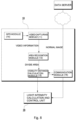
- the visibility distance measurement step S10 may utilize various methods, but the method of utilizing video images captured in real time can proceed through the chronological steps as shown in FIG. 13 .
- the area recognition module 12 of the visibility distance measurement unit 10 divides the frame of an image extracted from the captured video into area units and identifies and extracts only the driving area where the vehicle drives from the divided areas S12. Subsequently, the visibility distance calculation module 13 of the visibility distance measurement unit 10 compares the driving area identified by the area recognition module 12 with an image of a normal driving area to ultimately determine the visibility distance information Md S13. At this time, the visibility distance measurement unit 10 of the driving vehicle is equipped with a GPS module 14 and a communication module 15 to receive the image of the normal driving area from the outside and compare the driving area with the received image.
- the appropriate light intensity calculation step S40 is the step in which the light intensity calculation and control unit 20 mounted on the driving vehicle calculates the appropriate light intensity Cd using the visibility distance information Md.
- the light intensity calculation and control unit 20 of the light intensity calculation module 21 may determine the appropriate light intensity Cd based on accumulated data obtained by measuring the light intensity of the rear lamps RL and the braking deceleration according to the visibility distance.
- the light intensity control step S50 is the step in which the light intensity calculation and control unit 20 controls the light intensity of the rear lamps RL in real time.
- the light intensity control module 22 of the light intensity calculation and control unit 20 controls the light intensity of the rear lamps RL in real time to display the appropriate light intensity Cd calculated by the light intensity calculation module 21.
- the automatic light intensity control method M for vehicle rear lamps of the present invention may further comprise a speed detection step S20 in which the speed detection unit 30 detects the speeds of the driving vehicle LV and the following vehicle FV in real time and transmits the detected speeds to the light intensity calculation and control unit 20 by controlling the light intensity based further on the speed of the following vehicle FV to thereby provide the optimal light intensity to the driver of the following vehicle FV.
- the speed detection unit 30 may comprise a relative speed detection module 32 that detects the relative speed of the following vehicle with respect to the driving vehicle, in addition to the driving speed detection module 31.
- the appropriate light intensity calculation step S40 determines the appropriate light intensity Cd by additionally reflecting information on the speeds of the driving vehicle LV and the following vehicle FV detected in real time, thus preventing the occurrence of a collision when the driver of a faster following vehicle FV recognizes the rear lamps RL of the driving vehicle LV belatedly.
- the automatic light intensity control method M for vehicle rear lamps of the present invention may further comprise a braking distance calculation step S30 in which the braking distance calculation module 25 of the light intensity calculation and control unit 20 calculates a difference s in an appropriate braking distance between the driving vehicle LV and the following vehicle FV based on the speed V l of the driving vehicle and the speed Vf of the following vehicle.
- the appropriate light intensity calculation step S40 may determine the appropriate light intensity Cd by calculating the difference s in an appropriate braking distance between the driving vehicle LV and the following vehicle FV and correcting the visibility distance information Md.
- the rear lamp RL may be further provided with an infrared LED, and in the light intensity control step S50, if the visibility distance information Md is below a reference value, the infrared control unit 40 may control the infrared LED of the rear lamp to be turned on.
- the infrared control unit 40 may be designed to control the amount of infrared rays of the infrared LED so that the distance or speed information of the driving vehicle can be transmitted as quantitative data.
Landscapes
- Engineering & Computer Science (AREA)
- Mechanical Engineering (AREA)
- Physics & Mathematics (AREA)
- Automation & Control Theory (AREA)
- Mathematical Physics (AREA)
- Transportation (AREA)
- Lighting Device Outwards From Vehicle And Optical Signal (AREA)
- Traffic Control Systems (AREA)
- General Engineering & Computer Science (AREA)
Applications Claiming Priority (1)
| Application Number | Priority Date | Filing Date | Title |
|---|---|---|---|
| KR1020230034782A KR102584771B1 (ko) | 2023-03-16 | 2023-03-16 | 시정거리 변화에 연동하는 자동차 리어 램프 자동 광도 조절장치 및 그 조절방법 |
Publications (1)
| Publication Number | Publication Date |
|---|---|
| EP4431338A1 true EP4431338A1 (de) | 2024-09-18 |
Family
ID=88295996
Family Applications (1)
| Application Number | Title | Priority Date | Filing Date |
|---|---|---|---|
| EP23205554.1A Pending EP4431338A1 (de) | 2023-03-16 | 2023-10-24 | Automatische lichtstärkeregeleinrichtung für fahrzeugrückleuchten in abhängigkeit von änderungen der sichtweite und steuerverfahren dafür |
Country Status (4)
| Country | Link |
|---|---|
| US (1) | US12552309B2 (de) |
| EP (1) | EP4431338A1 (de) |
| JP (1) | JP7705435B2 (de) |
| KR (1) | KR102584771B1 (de) |
Families Citing this family (1)
| Publication number | Priority date | Publication date | Assignee | Title |
|---|---|---|---|---|
| CN118973034B (zh) * | 2024-07-30 | 2025-07-11 | 河北铭智光电科技有限公司 | 智慧照明系统及控制方法 |
Citations (9)
| Publication number | Priority date | Publication date | Assignee | Title |
|---|---|---|---|---|
| DE4206142A1 (de) * | 1992-02-28 | 1993-09-02 | Bosch Gmbh Robert | Vorrichtung zur sichtweitenabhaengigen steuerung der lichtabgabe von nebelleuchten bei fahrzeugen |
| EP0816168B1 (de) * | 1996-06-28 | 2002-07-31 | Thomas Rudel | Einrichtung zur Übertragung von Informationen von Fahrzeug zur Fahrzeug |
| DE102005054497A1 (de) * | 2005-11-16 | 2007-05-31 | Daimlerchrysler Ag | Kraftfahrzeug mit Rücklichtern und einer Auffahrwarnvorrichtung |
| EP1476326B1 (de) * | 2002-02-08 | 2008-04-09 | Robert Bosch Gmbh | Einrichtung zur automatischen einstellung der leuchtdichte des von einer rückwärtigen beleuchtungseinrichtung eines fahrzeugs ausgesandten lichtbündels |
| EP2067660A2 (de) * | 2007-12-06 | 2009-06-10 | Robert Bosch GmbH | Verfahren zum Verringern der Helligkeitsabgabe von Leuchtmitteln und Vorrichtung zum Vermindern der Helligkeit von Leuchtmitteln bei Fahrzeugen |
| KR101155870B1 (ko) | 2009-12-28 | 2012-06-20 | 콘티넨탈 오토모티브 일렉트로닉스 유한회사 | 자동차의 후미등 디밍 제어 방법 |
| KR101273448B1 (ko) | 2012-05-29 | 2013-06-11 | 한국건설기술연구원 | 자동 휘도 조절 시스템 |
| FR2988052A1 (fr) * | 2012-03-15 | 2013-09-20 | Valeo Systemes Dessuyage | Procede d'adaptation d'au moins un parametre photometrique d'une source lumineuse de vehicule automobile et systeme d'adaptation correspondant |
| CN105774639A (zh) * | 2014-12-15 | 2016-07-20 | 常州星宇车灯股份有限公司 | 组合尾灯的激光后雾灯及其使用方法 |
Family Cites Families (9)
| Publication number | Priority date | Publication date | Assignee | Title |
|---|---|---|---|---|
| EP1521980B1 (de) | 2002-07-05 | 2015-06-17 | Continental Teves AG & Co. oHG | System zur vermeidung eines auffahrunfalls |
| US8182125B2 (en) * | 2006-11-07 | 2012-05-22 | Rosco Inc. | External safety illumination for a bus with light mounted to mirror arm |
| KR20140030726A (ko) | 2012-09-03 | 2014-03-12 | 에스엘 주식회사 | 안개 상황에서의 차량 추돌 방지 장치 |
| KR101527932B1 (ko) * | 2013-05-24 | 2015-06-17 | 서정대학교 산학협력단 | 차량 급제동 또는 충돌 사고 경고 장치 및 이를 이용한 시스템 |
| US8944656B1 (en) | 2013-11-13 | 2015-02-03 | E-Lead Electronic Co., Ltd. | Vehicle infrared projection device |
| WO2016073590A1 (en) * | 2014-11-06 | 2016-05-12 | Gentex Corporation | System and method for visibility range detection |
| JP2017193277A (ja) * | 2016-04-21 | 2017-10-26 | 株式会社東海理化電機製作所 | 車両用視認装置 |
| WO2018043953A1 (ko) * | 2016-08-31 | 2018-03-08 | 박경준 | 차량 후방 미등 휘도 자동조절 방법 및 장치 |
| KR102395308B1 (ko) * | 2017-12-29 | 2022-05-09 | 현대자동차주식회사 | 군집주행차량의 램프 제어 장치 및 그 방법 |
-
2023
- 2023-03-16 KR KR1020230034782A patent/KR102584771B1/ko active Active
- 2023-10-24 EP EP23205554.1A patent/EP4431338A1/de active Pending
- 2023-10-25 US US18/494,362 patent/US12552309B2/en active Active
- 2023-10-27 JP JP2023184354A patent/JP7705435B2/ja active Active
Patent Citations (9)
| Publication number | Priority date | Publication date | Assignee | Title |
|---|---|---|---|---|
| DE4206142A1 (de) * | 1992-02-28 | 1993-09-02 | Bosch Gmbh Robert | Vorrichtung zur sichtweitenabhaengigen steuerung der lichtabgabe von nebelleuchten bei fahrzeugen |
| EP0816168B1 (de) * | 1996-06-28 | 2002-07-31 | Thomas Rudel | Einrichtung zur Übertragung von Informationen von Fahrzeug zur Fahrzeug |
| EP1476326B1 (de) * | 2002-02-08 | 2008-04-09 | Robert Bosch Gmbh | Einrichtung zur automatischen einstellung der leuchtdichte des von einer rückwärtigen beleuchtungseinrichtung eines fahrzeugs ausgesandten lichtbündels |
| DE102005054497A1 (de) * | 2005-11-16 | 2007-05-31 | Daimlerchrysler Ag | Kraftfahrzeug mit Rücklichtern und einer Auffahrwarnvorrichtung |
| EP2067660A2 (de) * | 2007-12-06 | 2009-06-10 | Robert Bosch GmbH | Verfahren zum Verringern der Helligkeitsabgabe von Leuchtmitteln und Vorrichtung zum Vermindern der Helligkeit von Leuchtmitteln bei Fahrzeugen |
| KR101155870B1 (ko) | 2009-12-28 | 2012-06-20 | 콘티넨탈 오토모티브 일렉트로닉스 유한회사 | 자동차의 후미등 디밍 제어 방법 |
| FR2988052A1 (fr) * | 2012-03-15 | 2013-09-20 | Valeo Systemes Dessuyage | Procede d'adaptation d'au moins un parametre photometrique d'une source lumineuse de vehicule automobile et systeme d'adaptation correspondant |
| KR101273448B1 (ko) | 2012-05-29 | 2013-06-11 | 한국건설기술연구원 | 자동 휘도 조절 시스템 |
| CN105774639A (zh) * | 2014-12-15 | 2016-07-20 | 常州星宇车灯股份有限公司 | 组合尾灯的激光后雾灯及其使用方法 |
Also Published As
| Publication number | Publication date |
|---|---|
| KR102584771B1 (ko) | 2023-10-06 |
| JP7705435B2 (ja) | 2025-07-09 |
| US20240308420A1 (en) | 2024-09-19 |
| US12552309B2 (en) | 2026-02-17 |
| JP2024132831A (ja) | 2024-10-01 |
Similar Documents
| Publication | Publication Date | Title |
|---|---|---|
| US9827956B2 (en) | Method and device for detecting a braking situation | |
| US10336254B2 (en) | Camera assisted vehicle lamp diagnosis via vehicle-to-vehicle communication | |
| US11325522B2 (en) | Automatic light system | |
| EP2537709B1 (de) | Bildverarbeitungsvorrichtung und Lichtverteilungssteuerverfahren | |
| EP3553761B1 (de) | Verfahren und vorrichtung zur durchführung einer differentialanalyse von fahrzeugen | |
| US20220194425A1 (en) | Method for operating a vehicle configured for automated, in particular highly automated or autonomous driving | |
| US20090243823A1 (en) | Vehicle environment recognition apparatus and preceding-vehicle follow-up control system | |
| US11498589B2 (en) | Vehicle-mounted equipment control device | |
| US20200410788A1 (en) | Management apparatus, vehicle, inspection apparatus, and vehicle inspection system and inforamtion processing method therefor | |
| US20210162962A1 (en) | Apparatus and method for controlling vehicle | |
| US20070208500A1 (en) | System for detecting vehicle traffic by means of an on-board co-operational telematic platform based upon extended floating car data | |
| EP4431338A1 (de) | Automatische lichtstärkeregeleinrichtung für fahrzeugrückleuchten in abhängigkeit von änderungen der sichtweite und steuerverfahren dafür | |
| CN114312794A (zh) | 车辆行驶恶劣天气环境的识别系统和方法 | |
| KR20200075692A (ko) | 좌표계를 이용한 안개 탐지 장치 및 그 방법 | |
| JPH08212499A (ja) | 先行車接近警報装置 | |
| CN118538053A (zh) | 预警临界距离、制动临界距离确定方法及融合4d毫米波雷达和单目视觉摄像头的车辆协同安全交互系统 | |
| CN111401124A (zh) | 点云与图像相交以确定到车辆应用中彩色光源的范围 | |
| US20250074291A1 (en) | Vehicle headlight evaluation | |
| US12236786B2 (en) | Calibration of time to collision threshold in low light conditions | |
| CN118457421A (zh) | 基于机动车尾灯的智能预警方法、系统及智能尾灯设备 | |
| CN114312838B (zh) | 一种车辆的控制方法、装置及存储介质 | |
| KR102171949B1 (ko) | 카메라를 이용한 차량 램프 밝기제어장치 | |
| CN119785622B (zh) | 一种基于自动驾驶车辆的机非碰撞预警系统及方法 | |
| CN113345217B (zh) | 一种虚拟警示墙生成方法、装置及计算机设备 | |
| CN217085550U (zh) | 一种智能网联的汽车安全数据监测装置及系统 |
Legal Events
| Date | Code | Title | Description |
|---|---|---|---|
| PUAI | Public reference made under article 153(3) epc to a published international application that has entered the european phase |
Free format text: ORIGINAL CODE: 0009012 |
|
| STAA | Information on the status of an ep patent application or granted ep patent |
Free format text: STATUS: REQUEST FOR EXAMINATION WAS MADE |
|
| 17P | Request for examination filed |
Effective date: 20231025 |
|
| AK | Designated contracting states |
Kind code of ref document: A1 Designated state(s): AL AT BE BG CH CY CZ DE DK EE ES FI FR GB GR HR HU IE IS IT LI LT LU LV MC ME MK MT NL NO PL PT RO RS SE SI SK SM TR |
|
| STAA | Information on the status of an ep patent application or granted ep patent |
Free format text: STATUS: EXAMINATION IS IN PROGRESS |
|
| 17Q | First examination report despatched |
Effective date: 20250515 |