EP4431420A1 - Installation de préparation de commandes - Google Patents
Installation de préparation de commandes Download PDFInfo
- Publication number
- EP4431420A1 EP4431420A1 EP24161808.1A EP24161808A EP4431420A1 EP 4431420 A1 EP4431420 A1 EP 4431420A1 EP 24161808 A EP24161808 A EP 24161808A EP 4431420 A1 EP4431420 A1 EP 4431420A1
- Authority
- EP
- European Patent Office
- Prior art keywords
- conveyor
- piece goods
- goods
- piece
- transfer
- Prior art date
- Legal status (The legal status is an assumption and is not a legal conclusion. Google has not performed a legal analysis and makes no representation as to the accuracy of the status listed.)
- Pending
Links
Images


Classifications
-
- B—PERFORMING OPERATIONS; TRANSPORTING
- B65—CONVEYING; PACKING; STORING; HANDLING THIN OR FILAMENTARY MATERIAL
- B65G—TRANSPORT OR STORAGE DEVICES, e.g. CONVEYORS FOR LOADING OR TIPPING, SHOP CONVEYOR SYSTEMS OR PNEUMATIC TUBE CONVEYORS
- B65G1/00—Storing articles, individually or in orderly arrangement, in warehouses or magazines
- B65G1/02—Storage devices
- B65G1/04—Storage devices mechanical
- B65G1/137—Storage devices mechanical with arrangements or automatic control means for selecting which articles are to be removed
- B65G1/1373—Storage devices mechanical with arrangements or automatic control means for selecting which articles are to be removed for fulfilling orders in warehouses
- B65G1/1376—Storage devices mechanical with arrangements or automatic control means for selecting which articles are to be removed for fulfilling orders in warehouses the orders being assembled on a commissioning conveyor
-
- G—PHYSICS
- G06—COMPUTING OR CALCULATING; COUNTING
- G06Q—INFORMATION AND COMMUNICATION TECHNOLOGY [ICT] SPECIALLY ADAPTED FOR ADMINISTRATIVE, COMMERCIAL, FINANCIAL, MANAGERIAL OR SUPERVISORY PURPOSES; SYSTEMS OR METHODS SPECIALLY ADAPTED FOR ADMINISTRATIVE, COMMERCIAL, FINANCIAL, MANAGERIAL OR SUPERVISORY PURPOSES, NOT OTHERWISE PROVIDED FOR
- G06Q10/00—Administration; Management
- G06Q10/08—Logistics, e.g. warehousing, loading or distribution; Inventory or stock management
- G06Q10/087—Inventory or stock management, e.g. order filling, procurement or balancing against orders
-
- B—PERFORMING OPERATIONS; TRANSPORTING
- B65—CONVEYING; PACKING; STORING; HANDLING THIN OR FILAMENTARY MATERIAL
- B65G—TRANSPORT OR STORAGE DEVICES, e.g. CONVEYORS FOR LOADING OR TIPPING, SHOP CONVEYOR SYSTEMS OR PNEUMATIC TUBE CONVEYORS
- B65G1/00—Storing articles, individually or in orderly arrangement, in warehouses or magazines
- B65G1/02—Storage devices
- B65G1/04—Storage devices mechanical
- B65G1/137—Storage devices mechanical with arrangements or automatic control means for selecting which articles are to be removed
- B65G1/1373—Storage devices mechanical with arrangements or automatic control means for selecting which articles are to be removed for fulfilling orders in warehouses
- B65G1/1378—Storage devices mechanical with arrangements or automatic control means for selecting which articles are to be removed for fulfilling orders in warehouses the orders being assembled on fixed commissioning areas remote from the storage areas
-
- B—PERFORMING OPERATIONS; TRANSPORTING
- B65—CONVEYING; PACKING; STORING; HANDLING THIN OR FILAMENTARY MATERIAL
- B65G—TRANSPORT OR STORAGE DEVICES, e.g. CONVEYORS FOR LOADING OR TIPPING, SHOP CONVEYOR SYSTEMS OR PNEUMATIC TUBE CONVEYORS
- B65G15/00—Conveyors having endless load-conveying surfaces, i.e. belts and like continuous members, to which tractive effort is transmitted by means other than endless driving elements of similar configuration
- B65G15/22—Conveyors having endless load-conveying surfaces, i.e. belts and like continuous members, to which tractive effort is transmitted by means other than endless driving elements of similar configuration comprising a series of co-operating units
-
- B—PERFORMING OPERATIONS; TRANSPORTING
- B65—CONVEYING; PACKING; STORING; HANDLING THIN OR FILAMENTARY MATERIAL
- B65G—TRANSPORT OR STORAGE DEVICES, e.g. CONVEYORS FOR LOADING OR TIPPING, SHOP CONVEYOR SYSTEMS OR PNEUMATIC TUBE CONVEYORS
- B65G47/00—Article or material-handling devices associated with conveyors; Methods employing such devices
- B65G47/52—Devices for transferring articles or materials between conveyors i.e. discharging or feeding devices
- B65G47/60—Devices for transferring articles or materials between conveyors i.e. discharging or feeding devices to or from conveyors of the suspended, e.g. trolley, type
- B65G47/61—Devices for transferring articles or materials between conveyors i.e. discharging or feeding devices to or from conveyors of the suspended, e.g. trolley, type for articles
-
- B—PERFORMING OPERATIONS; TRANSPORTING
- B65—CONVEYING; PACKING; STORING; HANDLING THIN OR FILAMENTARY MATERIAL
- B65G—TRANSPORT OR STORAGE DEVICES, e.g. CONVEYORS FOR LOADING OR TIPPING, SHOP CONVEYOR SYSTEMS OR PNEUMATIC TUBE CONVEYORS
- B65G57/00—Stacking of articles
- B65G57/02—Stacking of articles by adding to the top of the stack
- B65G57/03—Stacking of articles by adding to the top of the stack from above
- B65G57/06—Gates for releasing articles
-
- B—PERFORMING OPERATIONS; TRANSPORTING
- B65—CONVEYING; PACKING; STORING; HANDLING THIN OR FILAMENTARY MATERIAL
- B65G—TRANSPORT OR STORAGE DEVICES, e.g. CONVEYORS FOR LOADING OR TIPPING, SHOP CONVEYOR SYSTEMS OR PNEUMATIC TUBE CONVEYORS
- B65G57/00—Stacking of articles
- B65G57/02—Stacking of articles by adding to the top of the stack
- B65G57/09—Stacking of articles by adding to the top of the stack from alongside
- B65G57/10—Stacking of articles by adding to the top of the stack from alongside by devices, e.g. reciprocating, acting directly on articles for horizontal transport to the top of stack
-
- B—PERFORMING OPERATIONS; TRANSPORTING
- B65—CONVEYING; PACKING; STORING; HANDLING THIN OR FILAMENTARY MATERIAL
- B65G—TRANSPORT OR STORAGE DEVICES, e.g. CONVEYORS FOR LOADING OR TIPPING, SHOP CONVEYOR SYSTEMS OR PNEUMATIC TUBE CONVEYORS
- B65G13/00—Roller-ways
- B65G13/08—Roller-ways of curved form; with branch-offs
- B65G13/10—Switching arrangements
-
- B—PERFORMING OPERATIONS; TRANSPORTING
- B65—CONVEYING; PACKING; STORING; HANDLING THIN OR FILAMENTARY MATERIAL
- B65G—TRANSPORT OR STORAGE DEVICES, e.g. CONVEYORS FOR LOADING OR TIPPING, SHOP CONVEYOR SYSTEMS OR PNEUMATIC TUBE CONVEYORS
- B65G39/00—Rollers, e.g. drive rollers, or arrangements thereof incorporated in roller-ways or other types of mechanical conveyors
- B65G39/02—Adaptations of individual rollers and supports therefor
-
- B—PERFORMING OPERATIONS; TRANSPORTING
- B65—CONVEYING; PACKING; STORING; HANDLING THIN OR FILAMENTARY MATERIAL
- B65G—TRANSPORT OR STORAGE DEVICES, e.g. CONVEYORS FOR LOADING OR TIPPING, SHOP CONVEYOR SYSTEMS OR PNEUMATIC TUBE CONVEYORS
- B65G47/00—Article or material-handling devices associated with conveyors; Methods employing such devices
- B65G47/22—Devices influencing the relative position or the attitude of articles during transit by conveyors
Definitions
- the present disclosure relates to an order picking system with a transfer device having a horizontally movable transfer element, as well as a method for transporting and providing piece goods by means of the order picking system.
- DE10346122A1 was on 21.04.2005 on behalf of Beumer Maschinenfabrik GmbH & Co. KG published and discloses a device for feeding piece goods onto a sorter, with a feed conveyor from which the piece goods are preferably fed in a predetermined orientation and at its discharge end are to be transferred individually to a receiving station of a receiving conveyor immediately downstream of the feed conveyor, from which one piece goods part is to be transferred in a controlled manner to a receiving station of the sorter downstream of the receiving conveyor.
- An intermediate conveyor with a support plate for receiving the piece goods arranged above the conveying level of the receiving conveyor and which can be driven reversibly in the conveying direction of the feed conveyor is used to deliver the piece goods to the receiving conveyor.
- CH719043A1 was published on 14.04.2023 published in the name of the applicant and discloses a transfer device for transferring conveyed goods, such as lying goods, from a feed conveyor to conveyor positions of a removal conveyor.
- the transfer device forms a stationary receiving space for at least one conveyed item, which is limited at the bottom by a movable support member.
- the support member can be moved by means of a movement device between a support position in which the at least one conveyed item rests flat on the support member, and a discharge position in which the conveyed item falls downwards by gravity through an exposed transfer opening onto a conveyor position of the removal conveyor that moves past below the receiving space.
- B2B business-to-business
- B2C business-to-customer
- General cargo can be a very wide range of different products. For example, both inherently stable products, such as packages, boxes or books, and flexible and essentially flat general cargo such as magazines or even individual loose items of clothing packaged only in a flexible protective cover, have to be picked at the same time.
- One object of the invention can be seen in providing a picking system that enables more efficient preparation of consignments of goods for packaging with a wide variety of product categories.
- An order picking system for transporting and providing piece goods usually comprises at least one conveying device.
- the conveying device comprises an overhead conveyor for conveying the piece goods, as well as a delivery station for delivering the piece goods from the overhead conveyor to a transfer device for assembling the conveyed piece goods.
- the transfer device typically has a horizontally movable transfer element by means of which the piece goods can be assembled at an assembly station by gravity.
- horizontal is not to be understood in the geometric sense as exactly vertical to the vertical, but also includes an inclination of ⁇ 10°.
- the transfer element can be used to simply transfer the piece goods to a downstream device.
- the assembly station is typically arranged on a conveyor.
- the transfer element can also be controlled in such a way that piece goods conveyed one after the other can be stacked on an assembly station or can be transferred to a common assembly station offset from one another and/or at least partially overlapping one another.
- An alternative order picking system for transporting and providing piece goods can also be provided.
- This can also comprise a feed device which comprises an overhead conveyor for conveying the piece goods, as well as a delivery station for delivering the piece goods from the overhead conveyor to a transfer device.
- the transfer device can have a feed conveyor for assembling the piece goods delivered from the delivery station, by means of which the piece goods can be assembled at an assembly station by means of gravity.
- the piece goods can be taken from the delivery station by means of the feed conveyor and transported further to an assembly station.
- This assembly station can be arranged on a discharge conveyor, with the piece goods being transferred from the feed conveyor to the discharge conveyor by means of gravity. The piece goods cannot be transferred in an orderly manner from the feed conveyor into a pile at the assembly station.
- the piece goods are delivered to the transfer device by means of the overhead conveyor.
- the overhead conveyor of the delivery device typically comprises overhead conveyor receiving means in the form of pockets, baskets, bags or carrying loops, by means of which the piece goods can be conveyed in a hanging manner.
- the overhead conveyor receiving means in the form of pockets, baskets, bags or carrying loops for delivering the piece goods from the overhead conveyor can be emptied, in particular emptied by pivoting the overhead conveyor receiving means.
- the overhead conveyor typically comprises at least one rail on which the overhead conveyor means can be conveyed suspended by means of a carriage.
- the overhead conveyor means can typically be emptied via an opening on the top or via an opening in the side. To do this, they can be swiveled backwards in order to empty a piece of goods held in them via the opening on the top or they can be swiveled to the side in order to empty the piece of goods held in them via the opening in the side.
- the overhead conveyor receiving means can be designed in the form of overhead conveyor pockets with a rear wall and a front wall, which are flexibly connected to one another at least via a base section such that they can be moved back and forth between a first state in which they form an open and fillable pocket, and a second state in which they lie close to one another and form a folded-up pocket.
- the overhead conveyor typically connects directly to the delivery station, which usually includes an emptying device.
- the overhead conveyor or several overhead conveyors can connect the transfer device to devices arranged upstream.
- the overhead conveyor can thus be used to combine the delivery of goods with the removal of goods within a logistics facility, thereby establishing the flow of goods.
- the emptying device can comprise a revolving conveyor belt for receiving piece goods transported in the overhead conveyor receiving means.
- the conveying path of the overhead conveyor and the conveying path of the conveyor belt can be arranged in relation to one another in such a way that the distance between the conveying path of the overhead conveyor and the conveying path of the conveyor belt continuously decreases, so that when a overhead conveyor receiving means is conveyed along the contact section, a front side of the overhead conveyor receiving means contacts the conveyor belt and comes to rest on it, and the overhead conveyor receiving means are pivoted backwards or alternatively to the side.
- the conveying path of the overhead conveyor and the conveying path of the conveyor belt can run essentially parallel to one another with a certain downward gradient, wherein the front side of the respective overhead conveyor receiving means continues to lie on the conveyor belt during conveying along the transfer section, so that the opening of the overhead conveyor receiving means is oriented obliquely downwards and the piece goods present in the overhead conveyor receiving means can be transferred from the overhead conveyor receiving means to the conveyor belt, preferably by gravity.
- the distance between the conveying path of the overhead conveyor and the conveying path of the conveyor belt can become continuously larger, so that when an overhead conveyor pick-up device is conveyed along the separation section, the emptied overhead conveyor pick-up device is lifted off the conveyor belt and swings back into the freely hanging position.
- the conveying speeds of the conveyor belt and those of the overhead conveyor are usually the same.
- the conveyor belt can have a plurality of outwardly directed transverse ribs arranged at equal distances along a circumference of the conveyor belt.
- the relative position of the ribs and the overhead conveyor receiving means is typically selected in such a way that in the contact section a rib catches up with the overhead conveyor receiving means, contacts the bottom section of the overhead conveyor receiving means and pushes it forward in the conveying direction until the overhead conveyor receiving means has changed to an emptying state.
- the overhead conveyor and the conveyor belt can be operated at the same speed.
- the overhead conveyor and the conveyor belt can constantly run at the same speed.
- the distance between the ribs can be selected so that during the conveyance of a suspended conveyor along the transfer section, a piece of goods present in the suspended conveyor slides out of the pocket onto the conveyor belt by gravity and is supported by gravity on the conveyor belt. slides further downwards until it is caught and held by the rib that runs ahead of the overhead conveyor.
- the ribs of the conveyor belt can also consist of a large number of parallel fingers.
- An upper end of the chute can have slots whose position corresponds to the fingers of the ribs of the conveyor belt, so that when the conveyor belt is deflected, the fingers of the ribs and the slots of the chute interact with each other in a meshing manner.
- the piece goods held back behind a rib can then be released in a timed manner and then transported further on the chute by gravity.
- Another conveyor can take over the released piece goods units from the chute.
- the piece goods delivered by the overhead conveyor at the delivery station are conveyed to the transfer device by means of the conveying device.
- the transfer device can have a conveyor adjacent to the delivery station.
- the conveyor can be designed as a belt or roller conveyor, for example. This can be used to convey the piece goods delivered at the delivery station, typically from the overhead conveyor receiving means of the overhead conveyor, to the transfer element. In particular, when emptying and feeding using a chute, the piece goods typically do not arrive at the transfer device in a precise cycle and at equal intervals.
- the conveyor can be operated in stop-and-go mode in order to be able to transfer the respective piece goods to the transfer element at the right time.
- the transfer element can typically be moved, in particular horizontally, between at least one receiving position for receiving a conveyed piece of goods and at least one delivery position for delivering a piece of goods located on the transfer element.
- the feed conveyor can be accelerated or braked so that the respective piece goods conveyed by the feed conveyor can be transferred to the transfer element in the receiving position in such a synchronized manner that in the delivery position it can also be transferred from the transfer element to a downstream discharge conveyor in a synchronized manner.
- the discharge conveyor is designed as a tray conveyor with separate trays, for example. In this case, piece goods must be transferred to the respective tray essentially in the middle to prevent the piece goods from falling out or becoming jammed between two consecutive trays.
- the transfer device can comprise an alignment module for this purpose, which comprises driven alignment elements by means of which the piece goods can be aligned along and/or laterally with respect to a conveying direction. Since, in particular in the case of conveying devices, a chute for forwarding the piece goods from the delivery station to the conveyor or the transfer element If the piece goods are not transferred in an aligned manner, the alignment module can preferably be arranged upstream of the conveyor in order to bring the alignment to a desired alignment.
- the alignment elements can be in the form of rollers, omnidirectional wheels or balls.
- Balls offer greater mobility and flexibility in a conveyor system application compared to rollers or omnidirectional wheels. They can rotate freely in all directions, allowing for a nearly frictionless ride through tight curves and around obstacles such as other piece goods. In addition, balls can distribute weight more evenly than rollers or wheels, resulting in less wear on the conveyor system. This in turn can lead to a longer conveyor system life and lower maintenance costs.
- each alignment module has a plurality of alignment elements. These can be driven individually and independently of one another in order to align a piece of goods along the conveying direction and/or laterally to it when being conveyed on the alignment module.
- a sensor unit can be arranged above the alignment module, by means of which an alignment of the piece of goods on the alignment module can be detected.
- the control device can be used to actively and directionally drive the alignment elements be aligned on the alignment module and/or spaced apart from a piece of goods arranged upstream or downstream.
- the piece of goods are then preferably aligned and spaced apart and transferred to the conveyor and from there transferred to the transfer element in synchronized fashion.
- the transfer element can be designed and moved at an accelerated rate so that the piece goods picked up on it can be transferred to the assembly station essentially motionless, driven by gravity, due to its horizontal inertia.
- the transfer element can be removed from under the piece goods lying on it by means of an accelerated, typically jerky movement. Due to its mass and the resulting inertia, the piece goods temporarily remain almost unchanged during a jerky movement before falling down due to gravity.
- the horizontally movable transfer element of the transfer device can, for example, be at least partially plate-shaped or designed as a plate that is optionally movably mounted in lateral guides or designed as a rotating plate that is rotatably mounted for transferring the piece goods, preferably below the conveyor.
- the plate can be designed as an inherently stable plate or as an unstable and guided plate.
- the plate typically has a coefficient of friction that allows the piece goods to slide on the plate due to its inertia when the plate is abruptly accelerated.
- the plate is at least partially made of a plastic or at least partially coated with a plastic with good sliding properties.
- An adhesive friction coefficient ⁇ H between the items on the transfer element is, for example, less than or equal to 0.5, preferably less than or equal to 0.25. Typical materials for this can be hard cotton fabric based on phenol or epoxy resin. Alternatively, polyamide (PA), polyterafluoroethylene (PTFE), polyterafluoroethylene (PE) or polyester terephthalate (PET) can also be used.
- the horizontally movable transfer element of the transfer device can also be designed as a belt conveyor with a movable belt section, preferably in the form of a telescopic conveyor belt.
- the movable belt section can be accelerated in such a way that it is retracted beneath the piece goods due to their inertia and the piece goods can thus be transferred by gravity.
- the transfer element can also be moved incrementally. This makes it possible to specifically control any position in between, in addition to simply controlling the pick-up position and the delivery position.
- the transfer element can be horizontally incrementally moved so that the piece goods can be transferred to the assembly station in a position that is preferably in the middle, off-center or stacked with other piece goods, stacked next to each other or overlapping. This makes it possible for the transfer device to be used for both individual and synchronized transfer to the assembly station. Assembly point is possible, for example a central transfer of a piece of goods into a transport tray of a tray conveyor. It is also possible to carry out a stacked transfer while the conveyor element of the discharge conveyor continues to move, in particular continuously.
- a particularly space-saving design can be achieved if the transfer element is arranged below the conveyor and can be moved horizontally with respect to a distal end of the conveyor.
- the transfer element for example in the form of a plate or a telescopic conveyor belt as explained in more detail above, as well as the drive of the transfer element can be arranged below the conveyor, which enables a particularly compact and horizontally particularly short transfer device.
- the transfer element In the receiving position, the transfer element can be arranged in a protruding manner with respect to a distal end of the conveyor in order to at least partially close a transfer area.
- This transfer area can be designed as a window or as a physically formed shaft, for example in the form of a funnel.
- the transfer element In the delivery position, the transfer element can be arranged in such a way be retracted under the conveyor in order to free up the transfer area.
- the transfer area can be limited by the distal end of the conveyor and by a stop arranged at a distance from it. The stop thus limits the transfer area and ensures that a piece of goods to be transferred through the transfer area to the assembly area also ends up in the assembly area.
- the assembly station is typically arranged on the discharge conveyor so that a picking group formed thereon can be conveyed away by means of the discharge conveyor.
- a picking group is understood to mean both an ordered and a disordered collection of piece goods.
- the discharge conveyor can be designed as a belt, roller or tray conveyor.
- the assembly station can be designed in the form of a virtual assembly station or as a physical frame that is arranged on the discharge conveyor.
- the assembly station can also be arranged within a receiving container that is arranged on the discharge conveyor.
- the receiving container can be designed as a box, carton, tray or tub.
- a frame for example a U-shaped frame, can also be used.
- the packages can be sent directly around the picking group.
- the picking group is placed on a flat cardboard box, which is cut to size after the picking group has been measured, folded around the picking group and then glued.
- the picking group can be formed directly on a flat piece of cardboard, which is placed on the conveyor.
- Films, bags or preferably rectangular or square flat cardboard strips can be provided as the starting material for the packaging.
- an endless belt of cardboard can also be provided on the conveyor.
- Packaging in the form of a shipping bag, a wrap made of film or a cardboard box can be formed around the picking group.
- the picking groups can be transferred to the cardboard track using the transfer element.
- Packaging can then be formed around the picking group assembled at the assembly station using the transfer element, preferably in the form of a cardboard box that is folded around the picking group. This does not simply mean packing in a cardboard box, but rather forming a cardboard box in the form of a package. Based on the recorded dimensions, length, width and height, a package can be formed by mechanically cutting, folding and gluing the flat starting material.
- additional inserts can be enclosed in a further step of the picking group before the packaging is formed.
- additional inserts can be enclosed in a further step of the picking group before the packaging is formed.
- invoices, brochures or advertising materials for example, invoices, brochures or advertising materials.
- Important information for shipping can be attached to the packaging, for example in the form of shipping labels.
- a sensor unit can be arranged at the distal end of the conveyor, by means of which the arrival of a piece of goods conveyed by the conveyor can be detected and based on a first sensor signal measured by the sensor unit and sent to a control device, the transfer element can be moved from the delivery position to the receiving position by means of the control device in order to receive the piece of goods conveyed and detected by the sensor.
- the receiving position can also be movable, so the transfer element can be moved together with the conveyor in order to improve the transfer to the transfer element. This can be particularly relevant for loosely packaged piece goods, such as clothing.
- the sensor unit can ensure the synchronous transfer by allowing the control device to control either the travel path of the transfer element and/or the acceleration of the transfer element based on the sensor signal. If, for example, a central transfer to a passing assembly station is desired, the control device can adjust the transfer element based on the first sensor signal in such a way that the central transfer is ensured.
- the control device can also be used to monitor the passing of the piece goods conveyed by the conveyor.
- a second sensor signal can be sent from the sensor unit to the control device and, based on the second sensor signal, the control device can detach the transfer element from the It must be possible to move the picked-up position back to the delivery position in order to transfer the picked-up items to the assembly station by gravity.
- the transfer device can define a transfer area, wherein the transfer element at least partially closes the transfer area and a piece of goods conveyed by the conveyor can be received on the transfer element. By means of the movement starting from the delivery position, the transfer element can at least release the transfer area in such a way that a piece of goods received on it can be transferred through the transfer area to the assembly station by gravity.
- the transfer device can comprise a detection device by means of which the layout of the picking group can be monitored in a top view and/or the outline or height of the picking group in a side view.
- the transfer area is preferably monitored by means of this detection device.
- the transfer device can comprise a stop for positioning the piece goods, with the transfer area typically being limited by the stop and the distal end of the conveyor, through which the piece goods can be transferred to the assembly area by gravity.
- the order picking system can be part of a logistics system.
- the logistics system typically also includes a storage device and/or a sorting device and/or a storage device.
- the piece goods are typically delivered to the input side of the logistics system, for example by means of a truck. After unloading, the general cargo is typically transported through the following areas of the logistics facility: delivery, goods receipt, storage, packaging and labeling, buffering, storage, sorting, distribution, packaging, removal, which is also typically carried out by truck.
- the logistics system can have a device for filling the overhead conveyors.
- the overhead conveyors When empty, the overhead conveyors are already arranged on the overhead conveyor in a waiting position using carriages.
- the carriages are mounted on a guide rail so that they can move in the direction of the guide rail, and the overhead conveyors are arranged hanging downwards on the carriage to pick up piece goods.
- the overhead conveyor receiving means can be transported hanging on a guide rail piece, which corresponds to a section of the guide rail and which can be optionally connected to one end of the first guide rail or the second guide rail.
- the overhead conveyor receiving means are typically rotated for filling.
- an operating arrangement is advantageously provided with which the transport elements can be rotated by a certain angle of rotation at a certain point on the conveyor path, whereby typically a suspension hook on the suspension of the overhead conveyor receiving means is moved from the first position to a second position or from the second position to the first position can be transferred.
- the repositioning of the overhead conveyor receiving means is advantageously carried out by rotating the overhead conveyor receiving means themselves, advantageously around a central axis.
- a brush arrangement or mechanical, electrical, magnetic or pneumatic actuating means are particularly advantageously provided as the active arrangement.
- the overhead conveyor receiving means are separated in a transfer area by means of a separation mechanism, for example by means of a conveyor screw.
- the piece goods to be fed in are fed in by means of a feed device, which typically comprises several conveyor units arranged one behind the other, each with a conveyor belt.
- the feed device can have a final conveyor unit in the form of a roller conveyor in the transfer area, over which the piece goods can roll and slide or slip from above into the overhead conveyor receiving means.
- a single overhead conveyor is moved along a feed conveyor line in the conveying direction with the receiving compartment running ahead in the conveying direction into the transfer area.
- the overhead conveyor is actively opened before or in the transfer area using an opening mechanism.
- the overhead conveyor typically rests with a first side on the final conveyor unit of the feed device, which consequently forms a support.
- the conveying of the overhead conveyor is stopped for the purpose of transferring a piece of goods.
- the overhead conveyor is therefore not in a conveying movement when the piece of goods is being transferred in the overhead conveyor.
- the feed device is used to convey a piece of goods lying on the conveyor surface of the conveyor units to the transfer area.
- the piece of goods slides over the roller conveyor of the final conveyor unit in a transfer direction through the receiving opening into the overhead conveyor receiving device.
- the overhead conveyor and the piece of goods are moved out of the transfer area by means of the carrier conveyor from the horizontal conveyor. During this process, the overhead conveyor receiving device rolls with one side on the roller conveyor of the final conveyor unit.
- the final conveyor unit with the roller conveyor can be swiveled away from its conveying position to clear the conveying path for the overhead conveyors loaded with the piece goods. As soon as the overhead conveyor loaded with the piece goods has been conveyed upwards out of the transfer area, a subsequent overhead conveyor can be conveyed into the transfer area.
- a batch buffer can also be provided for the provision of product groups. These product groups can be provided in the form of batches.
- the logistics system can also comprise one or more matrix sorters for sorting the goods in batches.
- a plurality of overhead conveyor receiving means each of which comprises a receiving unit, preferably in the form of an overhead conveyor receiving means, can be fed to a matrix sorter for sorting the goods.
- a matrix sorter can also have several sorting stages.
- the matrix sorter is arranged within the logistics system downstream of the batch buffer and/or the filling device, it can take over the already filled overhead conveyor receiving means from the batch buffer and/or the filling device.
- the matrix sorter typically comprises at least one circulating conveyor for conveying the overhead conveyor receiving means, as well as branches leading from it for sorting the overhead conveyor receiving means, wherein the logistics system has a control system which is designed to control the conveying speed of the circulating conveyor.
- the batch buffer can also have branches which are branched off from another conveyor, preferably a circulating conveyor.
- the circulating conveyor is usually designed to convey the overhead conveyor receiving means at a constant conveying speed.
- the control can be designed to control the conveying speed of the circulating conveyor such that the conveying speed of the circulating conveyor in at least one batch is higher than the constant conveying speed of the other conveyors.
- the circulating conveyor is typically designed to guide the overhead conveyor receiving means to and/or away from a sorting stage.
- a sorting stage of the matrix sorter can have a plurality of linear buffer sections which are connected to the circulating conveyor by switches.
- the buffer sections are preferably designed as branches and can be designed as gravity sections with a gradient such that the overhead conveyor receiving means can be conveyed in the gravity sections due to gravity.
- the batch buffer can also have a plurality of branches in the form of linear storage sections, in each of which preferably one or more batches can be stored.
- At least one measuring device can be arranged in front of the matrix sorter, which is designed to determine the parameters, preferably the weight and/or the size, of the overhead conveyor means and/or goods entering the matrix sorter and to transmit them to the control system.
- the logistics system can have a database in which the parameters, preferably the weight and/or size, of the overhead conveyor receiving means and/or goods entering the matrix sorter are stored.
- the matrix sorter can comprise a plurality of sorting stages and a plurality of sorting steps, each of which is assigned to one sorting stage or two sorting stages.
- the control is typically designed to control the conveying speed of each matrix conveyor individually.
- the logistics system can also include an intermediate storage facility. This is usually arranged before or after the batch buffer.
- the at least one intermediate storage facility typically has a dynamic storage facility for temporarily storing the goods/unit goods prepared for picking and a retrieval storage facility downstream of the dynamic storage facility for storing goods retrieved from the dynamic storage facility and pre-sorted in the process.
- the dynamic storage facility and the retrieval storage facility can be arranged within a common circulating conveyor and can be connected to one another via the common circulating conveyor.
- the circulating conveyor is typically a conveyor with which the goods can be conveyed in a closed circuit or loop.
- Actuable or switchable switches can be provided at various points on the circulating conveyor. The switches enable new goods to be brought into the circuit or goods circulating in the circuit to be taken out.
- the goods are divided into the overhead conveyor receiving means, preferably in the form of overhead conveyor pockets, which can be moved individually and added to or removed from the circuit.
- the goods circulating in circulation and stored in the dynamic storage are in a specific order, which is usually based on the staggered removal of the goods from the warehouse, but does not correspond to the batches of goods determined by the orders.
- the goods are already grouped together in a batch that corresponds to the orders, so that a subsequent matrix sorter or order picking system is relieved of sorting work and can be made smaller or eliminated entirely.
- the transfer device can have a conveyor adjacent to the delivery station of the conveyor device and the transfer element for assembling can be moved horizontally between a receiving position for receiving a piece of goods and a delivery position for delivering the piece of goods.
- the piece goods can be aligned along and/or laterally with respect to a conveying direction and/or spaced from a piece goods arranged upstream or downstream.
- the transfer element can be moved horizontally with respect to a distal end of the conveyor at the same time as the conveying for assembling in order to take over a piece of goods conveyed by the conveyor from the conveyor.
- the transfer element can be moved back relative to the distal end of the conveyor in order to assemble the piece goods already on the transfer element, so that the piece goods are transferred by gravity through the transfer area to the assembly station.
- the transfer element is preferably accelerated, particularly preferably retracted abruptly, so that the piece goods picked up on it remain essentially motionless in the horizontal position due to its inertia and then fall to the assembly point driven by gravity.
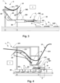
- FIG. 1 shows a first embodiment of the order picking system 1 when forming order picking groups KG.
- the order picking system 1 shown for transporting and providing piece goods S, S' comprises a conveying device 2, which comprises an overhead conveyor 21 for conveying the piece goods S, S'.
- the overhead conveyor 21 shown comprises overhead conveyor receiving means 211 in the form of overhead conveyor pockets, by means of which the piece goods S, S' can be conveyed in a hanging manner.
- the overhead conveyor pockets 211 are guided by means of carriages 212 on a rail 213 of the overhead conveyor 21. To empty the overhead conveyor pockets 211, these are pivoted as shown.
- the illustrated conveying device 2 Adjacent to the overhead conveyor 21, the illustrated conveying device 2 has a delivery station 22 for delivering the piece goods S, S' from the overhead conveyor 2.1 to a transfer device 3.
- the transfer device 3 For assembling the conveyed piece goods S, S', the transfer device 3 has a horizontally movable transfer element 31, by means of which the piece goods S, S' can be assembled by gravity at an assembly station P.
- the transfer device 3 is arranged adjacent to the delivery station 22 of the conveying device 2 and has a conveyor 32.
- the transfer element 31 can be arranged for transfer at least between a receiving position P1 for receiving a conveyed piece goods S and at least one delivery position P2 for delivering a piece goods S located on the transfer element 31.
- the transfer element 31 is moved further incrementally horizontally in the delivery position P2 when another piece of goods S is transferred, so that the piece of goods S is transferred in a positioned manner to the assembly station P.
- the piece of goods S, S' are transferred in an overlapping manner.
- Figure 2 shows the second embodiment of the order picking system 1 when forming order picking groups KG in the form of stacks. For this purpose, several piece goods S, S' are transferred one after the other essentially in the middle to the assembly station P. The piece goods S, S' are all positioned on top of each other.
- Figure 3 shows a second embodiment of the order picking system 1 with an alignment module 35 when forming order picking groups KG.
- the embodiment of the order picking system 1 shown also includes a conveying device 2 comprising an overhead conveyor 21 for conveying the piece goods S, S' and a delivery station 22 for delivering the piece goods S, S' from the overhead conveyor 21 to a transfer device 3 for assembling the conveyed piece goods S, S', which transfer device 3 has a horizontally movable transfer element 31, by means of which the piece goods S, S' can be assembled at an assembly station P by gravity.
- Figures 4 to 6 show a third embodiment of the order picking system 1.
- the embodiment of the order picking system 1 shown also includes a conveying device 2, comprising an overhead conveyor 21 for conveying the piece goods S, S' and a delivery station 22 for delivering the piece goods S, S' from the overhead conveyor 2.1 to a transfer device 3 for assembling the conveyed piece goods S, S', which transfer device 3 has a horizontally movable transfer element 31, by means of which the piece goods S, S' can be assembled by gravity at an assembly station P.
- a chute 23 is provided for transferring the piece goods S, S' from the delivery station 22 to the conveying device 32.
- the transfer element 31 shown is arranged below the conveyor 32 and can be moved horizontally with respect to a distal end 321 of the conveyor 32. In the receiving position P1 shown, the transfer element 31 is arranged protruding with respect to the distal end 321 in order to at least partially close the transfer area Z.
- a sensor unit 322 is arranged at the distal end 321 of the conveyor 32, by means of which the arrival of one of the piece goods S conveyed by the conveyor 32 can be detected and, based on a first sensor signal measured by the sensor unit 322 and sent to a control device 4, the transfer element 31 can be moved from the delivery position P2 to the receiving position P1 by means of the control device 4 in order to receive the piece goods S conveyed and detected by the sensor unit 322.
- Figure 5 shows the third embodiment of the order picking system 1 when transferring the first piece of goods S and simultaneously delivering another piece of goods S'.
- the transfer element 31 releases the transfer area Ü in such a way that the piece of goods on the transfer element 31 picked up piece goods S are transferred by gravity through the transfer area Ü to the assembly point P.
- Figure 6 shows the third embodiment of the order picking system 1 when the additional piece goods S' are transferred to the first piece goods S to form a stack. As shown, several piece goods S, S' are transferred one after the other essentially in the middle to the assembly station P. The piece goods S, S' are positioned one above the other and placed on top of one another.
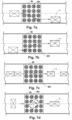
- FIG. 7 shows a variant of the alignment module 35.
- the alignment module 35 shown has driven alignment elements 351, by means of which the piece goods S can be aligned along and/or laterally with respect to a conveying direction X.
- the piece goods S, S' conveyed via the chute 23 of the conveyor device 2 do not arrive aligned.
- the alignment module 35 arranged upstream of the conveyor 32 in the embodiment shown has alignment elements 351 in the form of rollers, omnidirectional wheels or balls. Balls offer greater mobility and flexibility in a conveyor system application compared to rollers or omnidirectional wheels.
- the alignment elements 351 are driven individually and independently of one another in order to align the piece goods S, S' along the conveying direction X and/or laterally thereto when conveyed on the alignment module 35.
- FIGS. 7a and 7b show an alignment of piece goods S, S' with respect to the conveying direction X.
- Figure 7c shows a spacing of piece goods S, S' from each other along the conveying direction X and in Figure 7d shows a rotation of piece goods S.
- a sensor unit 352 is arranged above the alignment module 35, by means of which an alignment of the piece goods S on the alignment module 35 can be detected.
- the piece goods S is aligned by means of an active and directed driving of the alignment elements 351 on the alignment module 35 by means of the control device 4 and can additionally be spaced apart from a piece goods S' arranged upstream or downstream.
- the piece goods S are then transferred to the conveyor 32 in an aligned and spaced apart manner as shown and transferred from there to the transfer element 31.
- Figure 8 shows a flow chart of a logistics system which includes an example of an order picking system.
- the logistics system also includes a storage device and a sorting device, as well as a storage device.
- the piece goods are delivered to the entrance of the logistics system, for example by means of a truck.
- the logistics system can have a device for filling (S1) the overhead conveyors.
- S1 a device for filling
- the overhead conveyors are already arranged on the overhead conveyor using carriages and are kept ready in a waiting position.
- the carriages are mounted on a guide rail so that they can move in the direction of the guide rail, and the overhead conveyors are arranged hanging downwards to receive piece goods.
- the overhead conveyor receiving means can be transported hanging on a guide rail piece, which corresponds to a section of the guide rail and which can be optionally connected to one end of the first guide rail or the second guide rail.
- the overhead conveyor receiving means are typically rotated or pivoted for filling.
- an operating arrangement is advantageously provided with which the transport elements can be rotated at a certain point on the conveyor path by a certain angle of rotation to the vertical center axis of the overhead conveyor receiving means, whereby a suspension hook on the suspension of the overhead conveyor receiving means can typically be transferred from the first position to a second position or from the second position to the first position.
- pivoted overhead conveyor receiving means can be filled by means of a feed device.
- a batch buffer for the provision of groups of goods can also be provided for storing (S2) the piece goods within the logistics system.
- the logistics system can also comprise one or more matrix sorters for sorting the goods in batches (S3).
- a plurality of overhead conveyor receiving means each of which comprises a receiving unit, preferably in the form of an overhead conveyor receiving means, can be provided for receiving the goods in the matrix sorter.
- a matrix sorter can also have several sorting stages.
- the matrix sorter can sort the already filled Overhead conveyor receiving means of the batch buffer and/or the filling device.
- the matrix sorter typically comprises at least one circulating conveyor for conveying the overhead conveyor receiving means, wherein the logistics system has a control system which is designed to dynamically control the conveying speed of the circulating conveyor such that the conveying speed depends on at least one parameter, for example size and/or weight, of the conveyed overhead conveyor receiving means and/or goods.
- the overhead conveyor receiving means are typically buffered (S4).
- the batch buffer can have further conveyors, preferably further circulating conveyors, which are designed to convey the overhead conveyor receiving means at a constant conveying speed.
- the control can be designed to control the conveying speed of the matrix conveyor in such a way that the conveying speed of the matrix conveyor in at least one batch is higher than the constant conveying speed of the other conveyors.
- the circulating conveyor is typically designed to guide the overhead conveyor receiving means to and/or away from a sorting stage.
- a sorting stage of the matrix sorter can have a plurality of linear buffer sections in the form of branches, which are connected to the matrix conveyor by switches.
- the buffer sections are preferably designed as gravity sections with a gradient such that the overhead conveyor receiving means can be conveyed in the gravity sections due to gravity.
- the branches can be designed as a plurality of linear storage sections, in each of which preferably one batch or two batches can be stored.
- the logistics system can also have a database in which the parameters, preferably the weight and/or size, of the overhead conveyor receiving means and/or goods entering the matrix sorter are stored.
- the matrix sorter can comprise a plurality of sorting stages and a plurality of matrix conveyors, each of which is assigned to one sorting stage or two sorting stages.
- the control is typically designed to control the conveying speed of each circulating conveyor individually.
- the logistics system can also include an intermediate storage facility. This is usually arranged before or after the batch buffer.
- the at least one intermediate storage facility typically has a dynamic storage facility for temporarily storing the goods/unit goods prepared for picking and a retrieval storage facility downstream of the dynamic storage facility for storing goods retrieved from the dynamic storage facility and pre-sorted in the process.
- the dynamic storage facility and the retrieval storage facility can be arranged within a common circulating conveyor or can be connected to one another via the common circulating conveyor.
- the circulating conveyor is typically a conveyor with which the goods can be conveyed in a closed circuit or circuit.
- Actuable or switchable switches can be provided at various points on the circulating conveyor. The switches enable new goods to be brought into the circuit or goods circulating in the circuit to be taken out. Goods.
- the goods are divided into the overhead conveyor receiving means, preferably in the form of overhead conveyor pockets, which can each be moved individually and added to or removed from the circulation.
- the goods circulating in circulation and stored in the dynamic storage are in a specific order, which is usually based on the staggered removal of the goods from the warehouse, but does not correspond to the batches of goods determined by the orders.
- the goods are already grouped together in a batch that corresponds to the orders, so that a subsequent matrix sorter or order picking system is relieved of sorting work and can be made smaller or eliminated entirely.
- the goods consignments pre-sorted in this way and prepared for shipping are then conveyed to the order picking system (S7), in which the piece goods are transferred from the overhead conveyors (S8) and, after forming order picking groups (S9), are fed to the removal device for packaging (S10) and shipping (S11).
- the steps S7 - S9 are carried out by means of an order picking system according to the Figures 1 to 6 executed.
Landscapes
- Engineering & Computer Science (AREA)
- Mechanical Engineering (AREA)
- Business, Economics & Management (AREA)
- Economics (AREA)
- Human Resources & Organizations (AREA)
- Quality & Reliability (AREA)
- Finance (AREA)
- Entrepreneurship & Innovation (AREA)
- Accounting & Taxation (AREA)
- Marketing (AREA)
- Operations Research (AREA)
- Development Economics (AREA)
- Strategic Management (AREA)
- Tourism & Hospitality (AREA)
- Physics & Mathematics (AREA)
- General Business, Economics & Management (AREA)
- General Physics & Mathematics (AREA)
- Theoretical Computer Science (AREA)
- Intermediate Stations On Conveyors (AREA)
Applications Claiming Priority (4)
| Application Number | Priority Date | Filing Date | Title |
|---|---|---|---|
| CH000285/2023A CH720010A2 (de) | 2022-09-02 | 2023-03-13 | Fördersystem und Verfahren zur Förderung und Anpassung der Lage und/oder Beabstandung von Fördergütern |
| CH000578/2023A CH720818A1 (de) | 2023-05-31 | 2023-05-31 | Kommissionieranlage |
| CH000753/2023A CH720944A1 (de) | 2023-07-13 | 2023-07-13 | Förderanordnung und verfahren zum betreiben einer förderanordnung |
| CH001337/2023A CH720603A1 (de) | 2023-03-13 | 2023-11-30 | Kommissionieranlage |
Publications (1)
| Publication Number | Publication Date |
|---|---|
| EP4431420A1 true EP4431420A1 (fr) | 2024-09-18 |
Family
ID=90362336
Family Applications (1)
| Application Number | Title | Priority Date | Filing Date |
|---|---|---|---|
| EP24161808.1A Pending EP4431420A1 (fr) | 2023-03-13 | 2024-03-06 | Installation de préparation de commandes |
Country Status (2)
| Country | Link |
|---|---|
| US (1) | US20240311753A1 (fr) |
| EP (1) | EP4431420A1 (fr) |
Citations (9)
| Publication number | Priority date | Publication date | Assignee | Title |
|---|---|---|---|---|
| US5022218A (en) * | 1989-03-29 | 1991-06-11 | Bouwe Prakken | Device for filling outers with filled bags |
| DE10346122A1 (de) | 2003-10-01 | 2005-04-21 | Beumer Maschf Gmbh & Co Kg | Einschleusvorrichtung für einen Sorter |
| WO2010125111A1 (fr) * | 2009-05-01 | 2010-11-04 | Marel Food Systems Hf | Chargeur de lot |
| EP3357839A1 (fr) * | 2017-02-02 | 2018-08-08 | Siemens Aktiengesellschaft | Procédé et système de transport destinés à manipuler un flux de produits initial |
| WO2020140133A2 (fr) * | 2019-01-04 | 2020-07-09 | Tgw Logistics Group Gmbh | Station de préparation de commandes et procédé de préparation de commandes automatique et d'emballage automatique de marchandises |
| EP3733567A1 (fr) * | 2017-12-28 | 2020-11-04 | Itoh Denki Co., Ltd. | Dispositif et procédé de manutention de cargaison |
| WO2021011978A1 (fr) * | 2019-07-22 | 2021-01-28 | Tgw Logistics Group Gmbh | Dispositif de groupage de marchandises, système de stockage et de préparation des commandes et procédé d'empilement de marchandises et de fixation de l'empilement de marchandises à l'aide d'une bande |
| EP4163235A1 (fr) * | 2021-10-07 | 2023-04-12 | Ferag Ag | Dispositif de transfert de marchandises entre deux dispositifs de transport ainsi que système de transport et procédé de transfert |
| WO2024000005A1 (fr) * | 2022-06-30 | 2024-01-04 | Tgw Logistics Group Gmbh | Procédé et entrepôt de préparation pour préparer des marchandises de différentes commandes de préparation |
-
2024
- 2024-03-06 EP EP24161808.1A patent/EP4431420A1/fr active Pending
- 2024-03-11 US US18/601,579 patent/US20240311753A1/en active Pending
Patent Citations (10)
| Publication number | Priority date | Publication date | Assignee | Title |
|---|---|---|---|---|
| US5022218A (en) * | 1989-03-29 | 1991-06-11 | Bouwe Prakken | Device for filling outers with filled bags |
| DE10346122A1 (de) | 2003-10-01 | 2005-04-21 | Beumer Maschf Gmbh & Co Kg | Einschleusvorrichtung für einen Sorter |
| WO2010125111A1 (fr) * | 2009-05-01 | 2010-11-04 | Marel Food Systems Hf | Chargeur de lot |
| EP3357839A1 (fr) * | 2017-02-02 | 2018-08-08 | Siemens Aktiengesellschaft | Procédé et système de transport destinés à manipuler un flux de produits initial |
| EP3733567A1 (fr) * | 2017-12-28 | 2020-11-04 | Itoh Denki Co., Ltd. | Dispositif et procédé de manutention de cargaison |
| WO2020140133A2 (fr) * | 2019-01-04 | 2020-07-09 | Tgw Logistics Group Gmbh | Station de préparation de commandes et procédé de préparation de commandes automatique et d'emballage automatique de marchandises |
| WO2021011978A1 (fr) * | 2019-07-22 | 2021-01-28 | Tgw Logistics Group Gmbh | Dispositif de groupage de marchandises, système de stockage et de préparation des commandes et procédé d'empilement de marchandises et de fixation de l'empilement de marchandises à l'aide d'une bande |
| EP4163235A1 (fr) * | 2021-10-07 | 2023-04-12 | Ferag Ag | Dispositif de transfert de marchandises entre deux dispositifs de transport ainsi que système de transport et procédé de transfert |
| CH719043A1 (de) | 2021-10-07 | 2023-04-14 | Ferag Ag | Vorrichtung zur Übergabe von Fördergütern zwischen zwei Fördervorrichtungen sowie ein Fördersystem und ein Übergabeverfahren. |
| WO2024000005A1 (fr) * | 2022-06-30 | 2024-01-04 | Tgw Logistics Group Gmbh | Procédé et entrepôt de préparation pour préparer des marchandises de différentes commandes de préparation |
Also Published As
| Publication number | Publication date |
|---|---|
| US20240311753A1 (en) | 2024-09-19 |
Similar Documents
| Publication | Publication Date | Title |
|---|---|---|
| AT391671B (de) | Verfahren und vorrichtung zum automatischen stapeln, lagern und entnehmen von stueckgut | |
| CH713551A1 (de) | Verfahren zum Kommissionieren von Waren und Kommissionierungsanlage zur Durchführung des Verfahrens. | |
| EP1861327B1 (fr) | Dispositif et procede de transfert de piles | |
| AT405640B (de) | Kommissionieranlage | |
| EP4155237B1 (fr) | Dispositif et procédé de séquençage des unités de chargement dans un ordre prédéterminé | |
| DE19943361C1 (de) | Sortiereinrichtung für flache Sendungen | |
| DE102009052345B4 (de) | Automatisierte Kommissioniervorrichtung und Verfahren zum automatisierten Kommissionieren von Büchern, Medien, Prospekten und ähnlichen Gegenständen | |
| EP1020234B1 (fr) | Convoyeur de conteneurs d'envois | |
| EP4431420A1 (fr) | Installation de préparation de commandes | |
| EP0788452B1 (fr) | Installation pour la separation et le transfert d'articles plats | |
| DE69521919T2 (de) | Vorrichtung zum Zuführen und Sortieren von Gegenständen | |
| CH720603A1 (de) | Kommissionieranlage | |
| DE60008761T2 (de) | Ein fördersystem mit einer verschiebvorrichtung für artikel zwischen parallelen förderern | |
| DE19508911A1 (de) | Verfahren und Vorrichtung zum Stapeln von Stückgütern, insbesondere gebündelten Druckerzeugnissen | |
| EP4242142A1 (fr) | Dispositif, procédé et système de préparation de commandes de marchandises de détail | |
| DE10154437A1 (de) | Vorrichtung zum Sortieren und Stapeln von Stückgütern | |
| EP4455058A1 (fr) | Installation de préparation de commandes | |
| DE102024101042A1 (de) | Resthandsortiervorrichtung und Verfahren zum Sortieren von Resthandpoststücken | |
| EP4470945A1 (fr) | Installation de préparation de commandes | |
| EP0788453A1 (fr) | Dispositif a separer et a transferer des articles plats |
Legal Events
| Date | Code | Title | Description |
|---|---|---|---|
| PUAI | Public reference made under article 153(3) epc to a published international application that has entered the european phase |
Free format text: ORIGINAL CODE: 0009012 |
|
| STAA | Information on the status of an ep patent application or granted ep patent |
Free format text: STATUS: THE APPLICATION HAS BEEN PUBLISHED |
|
| AK | Designated contracting states |
Kind code of ref document: A1 Designated state(s): AL AT BE BG CH CY CZ DE DK EE ES FI FR GB GR HR HU IE IS IT LI LT LU LV MC ME MK MT NL NO PL PT RO RS SE SI SK SM TR |
|
| STAA | Information on the status of an ep patent application or granted ep patent |
Free format text: STATUS: REQUEST FOR EXAMINATION WAS MADE |
|
| 17P | Request for examination filed |
Effective date: 20250317 |