EP4431427A1 - Positive fadenliefervorrichtung, insbesondere für fadenliefervorrichtungen für schärmaschinen - Google Patents
Positive fadenliefervorrichtung, insbesondere für fadenliefervorrichtungen für schärmaschinen Download PDFInfo
- Publication number
- EP4431427A1 EP4431427A1 EP24161504.6A EP24161504A EP4431427A1 EP 4431427 A1 EP4431427 A1 EP 4431427A1 EP 24161504 A EP24161504 A EP 24161504A EP 4431427 A1 EP4431427 A1 EP 4431427A1
- Authority
- EP
- European Patent Office
- Prior art keywords
- yarn
- guide
- positive
- feeder according
- yarn feeder
- Prior art date
- Legal status (The legal status is an assumption and is not a legal conclusion. Google has not performed a legal analysis and makes no representation as to the accuracy of the status listed.)
- Granted
Links
Images


Classifications
-
- B—PERFORMING OPERATIONS; TRANSPORTING
- B65—CONVEYING; PACKING; STORING; HANDLING THIN OR FILAMENTARY MATERIAL
- B65H—HANDLING THIN OR FILAMENTARY MATERIAL, e.g. SHEETS, WEBS, CABLES
- B65H51/00—Forwarding filamentary material
- B65H51/20—Devices for temporarily storing filamentary material during forwarding, e.g. for buffer storage
- B65H51/22—Reels or cages, e.g. cylindrical, with storing and forwarding surfaces provided by rollers or bars
-
- D—TEXTILES; PAPER
- D02—YARNS; MECHANICAL FINISHING OF YARNS OR ROPES; WARPING OR BEAMING
- D02H—WARPING, BEAMING OR LEASING
- D02H1/00—Creels, i.e. apparatus for supplying a multiplicity of individual threads
-
- B—PERFORMING OPERATIONS; TRANSPORTING
- B65—CONVEYING; PACKING; STORING; HANDLING THIN OR FILAMENTARY MATERIAL
- B65H—HANDLING THIN OR FILAMENTARY MATERIAL, e.g. SHEETS, WEBS, CABLES
- B65H57/00—Guides for filamentary materials; Supports therefor
- B65H57/003—Arrangements for threading or unthreading the guide
-
- B—PERFORMING OPERATIONS; TRANSPORTING
- B65—CONVEYING; PACKING; STORING; HANDLING THIN OR FILAMENTARY MATERIAL
- B65H—HANDLING THIN OR FILAMENTARY MATERIAL, e.g. SHEETS, WEBS, CABLES
- B65H57/00—Guides for filamentary materials; Supports therefor
- B65H57/04—Guiding surfaces within slots or grooves
-
- D—TEXTILES; PAPER
- D02—YARNS; MECHANICAL FINISHING OF YARNS OR ROPES; WARPING OR BEAMING
- D02H—WARPING, BEAMING OR LEASING
- D02H13/00—Details of machines of the preceding groups
- D02H13/22—Tensioning devices
- D02H13/24—Tensioning devices for individual threads
-
- B—PERFORMING OPERATIONS; TRANSPORTING
- B65—CONVEYING; PACKING; STORING; HANDLING THIN OR FILAMENTARY MATERIAL
- B65H—HANDLING THIN OR FILAMENTARY MATERIAL, e.g. SHEETS, WEBS, CABLES
- B65H2701/00—Handled material; Storage means
- B65H2701/30—Handled filamentary material
- B65H2701/31—Textiles threads or artificial strands of filaments
Definitions
- the present invention relates to a positive yarn feeder particularly for yarn feeding apparatuses for warping machines.
- a plurality of yarns can conventionally be fed to a warping machine by one or more creels.
- a creel generally comprises a battery of spools supported by a frame extending on a vertical plane.
- the spools are generally arranged in multiple horizontal rows, e.g., eight horizontal rows each containing one hundred spools, for a total of eight hundred spools supported by a single creel.
- the warping machine can be fed by a pair of creels of the above type placed opposite to each other.
- Each one of the yarns can be fed in a controlled manner from the spool to the warping machine by means of a respective motorized yarn winding spool mounted on the creel.
- the rotation rate of each yarn winding spool is normally adjusted by control means on the basis of the signals received from at least one tension sensor that is functionally arranged between the yarn winding spool and the warping machine, in order to stabilize yarn tension at a fixed or variable predetermined level.
- the solution or embodiment described in EPA 23165702.4 has the advantage of allowing to adjust with high precision and flexibility the actual tension at which the yarns are fed to the warping machine.
- weft taker rod which essentially consists of a long flexible needle provided with a notched end to which the yarn to be threaded can be hooked.
- threading operations on the yarn feeder located at one end of the array may be relatively easy for the operator, since the yarn guiding eyelets and the yarn winding spool are exposed and more easily accessible, the same cannot be said for the other yarn feeders, where access to the yarn guiding eyelets and the yarn winding spool is partially hindered by the adjacent feeders.
- each array may comprise several dozen yarn feeders and, as a result, be more than one meter long.
- the operator during threading operations, in order to access the rear side of the yarn feeders located in the innermost positions, cannot go around the array laterally (i.e., at the ends) with his arms, because the length of the array does not allow this, but he can only "climb over" the array from above or below.
- the aim of the present invention is to provide a positive yarn feeder, particularly for yarn feeding apparatuses for warping machines, that makes threading operations easier, especially in relation to the use of such a yarn feeder in association with others arranged laterally adjacent to each other and at a short distance apart within an array.
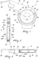
- a positive yarn feeder henceforth referred to as “feeder” 10 for brevity, comprises a support 12, an electric motor 14 fixed to the support 12, and a yarn winding spool 16 extending around an axis A, which is functionally connected to the electric motor 14 in order to be turned by the latter.
- the yarn winding spool 16 has a peripheral winding surface 16a on which a yarn Y is adapted to be wound.
- the feeder 10 is provided with an input yarn guiding eyelet 26 and an output yarn guiding eyelet 28 which are fixed to the plate 18 upstream and downstream of the yarn winding spool 16, respectively, with respect to the feeding direction of the yarn Y.
- the feeder 10 is also equipped with a tension sensor 30 arranged between the yarn winding spool 16 and the output yarn guiding eyelet 28.
- the yarn arriving at the feeder 10 passes through the input yarn guiding eyelet 26, is wound one or more times on the yarn winding spool 16 (only once in the embodiment shown in Figures 4-13 , which will be commented on hereinafter), engages the tension sensor 30, and finally passes through the output yarn guiding eyelet 28.
- rod P which essentially consists of a long flexible needle provided with a notched end P' to which the yarn to be threaded can be hooked.
- the feeder 10 comprises a guide 32 which partially surrounds the yarn winding spool 16 and has a guiding surface 32a which faces the peripheral winding surface 16a to form an interspace 33 adapted to guide the insertion and deformation, around the yarn winding spool 16, of the rod P, said guide 32 having a free input end 32' and a free output end 32" which define, between the peripheral winding surface 16a and the guiding surface 32a, an input passage 34' and an output passage 34" for the rod P, respectively.
- the guide 32 surrounds a sector of the yarn winding spool 16 on the opposite side of the axis A with respect to the input yarn guiding eyelet 26.
- the guide 32 has an annular sector portion that is extended around the axis A.
- annular sector portion 35 refers to the profile of the guiding surface 32a in that portion, since externally the guide 32 may have any suitable profile.
- the annular sector portion 35 has an angular extension comprised between 90° and 270°, more preferably approximately 180°.
- the guide 32 has a straight input portion 36' that extends tangentially from the annular sector portion 35 on the side of the free input end 32', so as to widen the input passage 34' and facilitate the insertion of the rod P.
- the guide 32 also has a straight output portion 36" which extends tangentially from the annular sector portion 35 on the side of free output end 32' so as to widen the output passage 34" and facilitate the extraction of the rod P.
- the definition "rectilinear” refers to the profile of the guiding surface 32a in said portion, since externally the guide 32 can have any suitable profile.
- the guide 32 has an overall angular extension ⁇ (i.e., annular sector portion 35, straight input portion 36' and straight output portion 36") comprised between 90° and 270°, more preferably approximately 200° ( Figure 1 ).
- ⁇ i.e., annular sector portion 35, straight input portion 36' and straight output portion 36
- the peripheral winding surface 16a of the yarn winding spool 16 has a cylindrical profile suitable for possibly accommodating multiple turns of yarn side by side, although in the embodiment described here and shown in Figures 4-13 , which will be commented on hereinafter, there is only one turn.
- the guiding surface 32a of the guide 32 has a concave profile, more preferably a trapezoidal concave profile with a cylindrical bottom surface 32a' delimited laterally between two mutually opposite frustoconical surfaces 32a", 32a'", which are adapted to guide and laterally retain the rod P during threading operations.
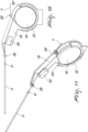
- FIGS 4-13 show five steps of the threading operations in sequence.
- the rod P is inserted again in the interspace 33 through the output passage 34" and extracted from the input passage 34", repeating the operation a number of times that corresponds to the number of turns of yarn Y that one wishes to wind.
- the feeder 10 according to the invention fully achieves its intended aim and object.
- the guide 32 considerably facilitates threading operations, especially when the feeder 10 is used in conjunction with other identical feeders arranged laterally adjacent to each other and a short distance apart within an array.
- Figure 14 shows schematically such an array of feeders 10 fixed to a generic structure F, for example the frame of a creel.
- the advantages of the invention are all the more appreciable as the number of feeders belonging to the array increases. This occurs because, as described in the preamble of this description, the difficulty for the operator to access the feeders increases as the length of the array increases.
- the advantages of the invention are even more appreciable when the operator has to perform the threading operations at a considerable height, for example on a ladder.
- the possibility to maneuver the rod with a single hand allows the operator to hold onto the ladder with the other hand, improving the comfort and safety conditions under which threading operations are performed.
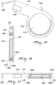
- FIGS 15-17 show an alternative embodiment of the feeder according to the invention.
- the elements that correspond to those of the previous embodiment are designated by the same reference numerals increased by 100.
- the feeder 110 differs from the one of the previous embodiment only in that the peripheral winding surface 116a of the yarn winding spool 116 has a concave profile, advantageously a V-shaped profile delimited between two mutually opposite frustoconical walls 116a', 116a", while the guiding surface 132a of the guide 132 has a cylindrical profile.
- the remaining elements of the feeder 110 can be identical to those of the previous embodiment and therefore their description will not be repeated.
- the V-shaped profile of the peripheral winding surface 116a is adapted to accommodate a single turn of yarn.
- the threading operations can be performed similarly to the previous embodiment, the only difference being that during the threading operations, the function of laterally guiding the rod in this case is performed by the frustoconical walls 116a', 116a" of the peripheral winding surface 116a of the spool.
- the guiding surface of the guide and the winding surface of the spool might also both have concave profiles or be both cylindrical.
- the invention is particularly advantageous in relation to feeders having a flattened shape and intended to be used in association with other identical feeders within an array the longitudinal footprint of which needs to be limited as much as possible.
- the invention may also advantageously apply to more traditional feeders in which, for example, the spool is conventionally keyed on the shaft of an electric motor arranged coaxially in front of the spool instead of being accommodated inside it.
- the support may coincide with the motor body of the motor itself.
Landscapes
- Engineering & Computer Science (AREA)
- Textile Engineering (AREA)
- Unwinding Of Filamentary Materials (AREA)
Applications Claiming Priority (1)
| Application Number | Priority Date | Filing Date | Title |
|---|---|---|---|
| IT102023000004716A IT202300004716A1 (it) | 2023-03-14 | 2023-03-14 | Alimentatore di filato positivo particolarmente per apparati di alimentazione di filato per orditoi. |
Publications (2)
| Publication Number | Publication Date |
|---|---|
| EP4431427A1 true EP4431427A1 (de) | 2024-09-18 |
| EP4431427B1 EP4431427B1 (de) | 2026-04-29 |
Family
ID=86604474
Family Applications (1)
| Application Number | Title | Priority Date | Filing Date |
|---|---|---|---|
| EP24161504.6A Active EP4431427B1 (de) | 2023-03-14 | 2024-03-05 | Positive fadenliefervorrichtung, insbesondere für fadenliefervorrichtungen für schärmaschinen |
Country Status (3)
| Country | Link |
|---|---|
| EP (1) | EP4431427B1 (de) |
| CN (1) | CN118653237A (de) |
| IT (1) | IT202300004716A1 (de) |
Families Citing this family (1)
| Publication number | Priority date | Publication date | Assignee | Title |
|---|---|---|---|---|
| IT202300004716A1 (it) | 2023-03-14 | 2024-09-14 | Lgl Electronics Spa | Alimentatore di filato positivo particolarmente per apparati di alimentazione di filato per orditoi. |
Citations (5)
| Publication number | Priority date | Publication date | Assignee | Title |
|---|---|---|---|---|
| US3858830A (en) * | 1973-08-20 | 1975-01-07 | Wesco Industries Corp | Positive yarn feeding device |
| GB1402177A (en) * | 1971-09-28 | 1975-08-06 | Wesco Industries Corp | Yarn storing device |
| US4121782A (en) * | 1976-05-22 | 1978-10-24 | Alan Shelton Limited | Yarn storage feeders |
| EP2664569A1 (de) * | 2012-05-17 | 2013-11-20 | L.G.L. Electronics S.p.A. | Garnzuführung mit Drehtrommeln für Textilmaschinen |
| IT202300004716A1 (it) | 2023-03-14 | 2024-09-14 | Lgl Electronics Spa | Alimentatore di filato positivo particolarmente per apparati di alimentazione di filato per orditoi. |
Family Cites Families (1)
| Publication number | Priority date | Publication date | Assignee | Title |
|---|---|---|---|---|
| IT202200007784A1 (it) | 2022-04-20 | 2023-10-20 | Lgl Electronics Spa | Metodo per l'alimentazione di una pluralità di filati ad un orditoio ed apparato per l'esecuzione di tale metodo |
-
2023
- 2023-03-14 IT IT102023000004716A patent/IT202300004716A1/it unknown
-
2024
- 2024-03-05 EP EP24161504.6A patent/EP4431427B1/de active Active
- 2024-03-12 CN CN202410280986.6A patent/CN118653237A/zh active Pending
Patent Citations (5)
| Publication number | Priority date | Publication date | Assignee | Title |
|---|---|---|---|---|
| GB1402177A (en) * | 1971-09-28 | 1975-08-06 | Wesco Industries Corp | Yarn storing device |
| US3858830A (en) * | 1973-08-20 | 1975-01-07 | Wesco Industries Corp | Positive yarn feeding device |
| US4121782A (en) * | 1976-05-22 | 1978-10-24 | Alan Shelton Limited | Yarn storage feeders |
| EP2664569A1 (de) * | 2012-05-17 | 2013-11-20 | L.G.L. Electronics S.p.A. | Garnzuführung mit Drehtrommeln für Textilmaschinen |
| IT202300004716A1 (it) | 2023-03-14 | 2024-09-14 | Lgl Electronics Spa | Alimentatore di filato positivo particolarmente per apparati di alimentazione di filato per orditoi. |
Also Published As
| Publication number | Publication date |
|---|---|
| IT202300004716A1 (it) | 2024-09-14 |
| EP4431427B1 (de) | 2026-04-29 |
| CN118653237A (zh) | 2024-09-17 |
Similar Documents
| Publication | Publication Date | Title |
|---|---|---|
| EP2503039B1 (de) | Positiver Garnzuführer mit Spannungsbegrenzer | |
| EP4431427A1 (de) | Positive fadenliefervorrichtung, insbesondere für fadenliefervorrichtungen für schärmaschinen | |
| CN104024505B (zh) | 用于将纱线供给至纺织机的设备 | |
| EP2868609B1 (de) | Garnbereitstellungssystem | |
| GB1562548A (en) | Chucks for yarn package tubes | |
| ITUA20164460A1 (it) | Alimentatore di filato con rocchetto avvolgi-filo motorizzato | |
| EP3334673B1 (de) | Verstellbarer fadenspanner und garnversorgungskanister | |
| RU2162816C2 (ru) | Нитеподающее устройство с улучшенным движением нити | |
| JPS6211098B2 (de) | ||
| EP4265831B1 (de) | Verfahren zum zuführen einer vielzahl von fäden zu einer schärmaschine und vorrichtung zur durchführung des verfahrens | |
| KR970000443B1 (ko) | 유체 분사 직기의 측정 위사 공급기용 위사 리저브 권취 유닛 | |
| EP2218670A1 (de) | Fadenliefervorrichtung mit einer leichten Fadenaufwickeltrommel | |
| EP0469527A1 (de) | Schussfadenspeicher für Luftwebmaschinen mit einer Aufwickeltrommel, deren Durchmesser verstellbar ist | |
| CN101649518B (zh) | 整经装置 | |
| JPS6411543B2 (de) | ||
| US5203518A (en) | Creel adapter | |
| CS276716B6 (en) | Apparatus for threads forwarding | |
| US2905399A (en) | Ring winding machine | |
| US4815672A (en) | Toroidal core coil winding appliance | |
| CN112209179B (zh) | 将多根纱线在受控张力下馈送到纺织机的方法 | |
| US1586767A (en) | Strand-traverse guide | |
| GB2044809A (en) | Thread metering devices | |
| CN111320027B (zh) | 用于捻线机的纺纱筒子架 | |
| CS205082B2 (en) | Yarn feeding device for multifeed circular knitting machines | |
| EP0329465B1 (de) | Fitzvorrichtung |
Legal Events
| Date | Code | Title | Description |
|---|---|---|---|
| PUAI | Public reference made under article 153(3) epc to a published international application that has entered the european phase |
Free format text: ORIGINAL CODE: 0009012 |
|
| STAA | Information on the status of an ep patent application or granted ep patent |
Free format text: STATUS: THE APPLICATION HAS BEEN PUBLISHED |
|
| AK | Designated contracting states |
Kind code of ref document: A1 Designated state(s): AL AT BE BG CH CY CZ DE DK EE ES FI FR GB GR HR HU IE IS IT LI LT LU LV MC ME MK MT NL NO PL PT RO RS SE SI SK SM TR |
|
| STAA | Information on the status of an ep patent application or granted ep patent |
Free format text: STATUS: REQUEST FOR EXAMINATION WAS MADE |
|
| 17P | Request for examination filed |
Effective date: 20240926 |
|
| RBV | Designated contracting states (corrected) |
Designated state(s): AL AT BE BG CH CY CZ DE DK EE ES FI FR GB GR HR HU IE IS IT LI LT LU LV MC ME MK MT NL NO PL PT RO RS SE SI SK SM TR |
|
| GRAP | Despatch of communication of intention to grant a patent |
Free format text: ORIGINAL CODE: EPIDOSNIGR1 |
|
| STAA | Information on the status of an ep patent application or granted ep patent |
Free format text: STATUS: GRANT OF PATENT IS INTENDED |
|
| INTG | Intention to grant announced |
Effective date: 20251009 |
|
| P01 | Opt-out of the competence of the unified patent court (upc) registered |
Free format text: CASE NUMBER: UPC_APP_0013070_4431427/2025 Effective date: 20251112 |
|
| GRAS | Grant fee paid |
Free format text: ORIGINAL CODE: EPIDOSNIGR3 |
|
| GRAA | (expected) grant |
Free format text: ORIGINAL CODE: 0009210 |
|
| STAA | Information on the status of an ep patent application or granted ep patent |
Free format text: STATUS: THE PATENT HAS BEEN GRANTED |