EP4431441A1 - Treuil - Google Patents
Treuil Download PDFInfo
- Publication number
- EP4431441A1 EP4431441A1 EP23161717.6A EP23161717A EP4431441A1 EP 4431441 A1 EP4431441 A1 EP 4431441A1 EP 23161717 A EP23161717 A EP 23161717A EP 4431441 A1 EP4431441 A1 EP 4431441A1
- Authority
- EP
- European Patent Office
- Prior art keywords
- drum
- frame
- winch
- sensing probes
- cable
- Prior art date
- Legal status (The legal status is an assumption and is not a legal conclusion. Google has not performed a legal analysis and makes no representation as to the accuracy of the status listed.)
- Withdrawn
Links
Images


Classifications
-
- B—PERFORMING OPERATIONS; TRANSPORTING
- B66—HOISTING; LIFTING; HAULING
- B66D—CAPSTANS; WINCHES; TACKLES, e.g. PULLEY BLOCKS; HOISTS
- B66D1/00—Rope, cable, or chain winding mechanisms; Capstans
- B66D1/54—Safety gear
- B66D1/58—Safety gear responsive to excess of load
-
- B—PERFORMING OPERATIONS; TRANSPORTING
- B66—HOISTING; LIFTING; HAULING
- B66D—CAPSTANS; WINCHES; TACKLES, e.g. PULLEY BLOCKS; HOISTS
- B66D5/00—Braking or detent devices characterised by application to lifting or hoisting gear, e.g. for controlling the lowering of loads
- B66D5/02—Crane, lift hoist, or winch brakes operating on drums, barrels, or ropes
-
- F—MECHANICAL ENGINEERING; LIGHTING; HEATING; WEAPONS; BLASTING
- F16—ENGINEERING ELEMENTS AND UNITS; GENERAL MEASURES FOR PRODUCING AND MAINTAINING EFFECTIVE FUNCTIONING OF MACHINES OR INSTALLATIONS; THERMAL INSULATION IN GENERAL
- F16C—SHAFTS; FLEXIBLE SHAFTS; ELEMENTS OR CRANKSHAFT MECHANISMS; ROTARY BODIES OTHER THAN GEARING ELEMENTS; BEARINGS
- F16C19/00—Bearings with rolling contact, for exclusively rotary movement
- F16C19/52—Bearings with rolling contact, for exclusively rotary movement with devices affected by abnormal or undesired conditions
- F16C19/522—Bearings with rolling contact, for exclusively rotary movement with devices affected by abnormal or undesired conditions related to load on the bearing, e.g. bearings with load sensors or means to protect the bearing against overload
-
- F—MECHANICAL ENGINEERING; LIGHTING; HEATING; WEAPONS; BLASTING
- F16—ENGINEERING ELEMENTS AND UNITS; GENERAL MEASURES FOR PRODUCING AND MAINTAINING EFFECTIVE FUNCTIONING OF MACHINES OR INSTALLATIONS; THERMAL INSULATION IN GENERAL
- F16C—SHAFTS; FLEXIBLE SHAFTS; ELEMENTS OR CRANKSHAFT MECHANISMS; ROTARY BODIES OTHER THAN GEARING ELEMENTS; BEARINGS
- F16C19/00—Bearings with rolling contact, for exclusively rotary movement
- F16C19/54—Systems consisting of a plurality of bearings with rolling friction
- F16C19/546—Systems with spaced apart rolling bearings including at least one angular contact bearing
-
- G—PHYSICS
- G01—MEASURING; TESTING
- G01L—MEASURING FORCE, STRESS, TORQUE, WORK, MECHANICAL POWER, MECHANICAL EFFICIENCY, OR FLUID PRESSURE
- G01L5/00—Apparatus for, or methods of, measuring force, work, mechanical power, or torque, specially adapted for specific purposes
- G01L5/04—Apparatus for, or methods of, measuring force, work, mechanical power, or torque, specially adapted for specific purposes for measuring tension in flexible members, e.g. ropes, cables, wires, threads, belts or bands
- G01L5/10—Apparatus for, or methods of, measuring force, work, mechanical power, or torque, specially adapted for specific purposes for measuring tension in flexible members, e.g. ropes, cables, wires, threads, belts or bands using electrical means
- G01L5/105—Apparatus for, or methods of, measuring force, work, mechanical power, or torque, specially adapted for specific purposes for measuring tension in flexible members, e.g. ropes, cables, wires, threads, belts or bands using electrical means using electro-optical means
Definitions
- the present invention relates to a winch for a ship, comprising a frame, a drum which is mounted to the frame through at least a bearing and rotatable with respect to the frame about an axis of rotation, a cable which is wound around the drum and a brake for locking the drum with respect to the frame, wherein under operating conditions a part of the cable that extends outwardly from the drum exerts a cable force on the drum and lies in a cable plane which extends tangentially with respect to the drum, hence causing a torque about the axis of rotation whereas the brake exerts a counter torque on the drum.
- Such a winch is known in the prior art.
- the known winch is provided with a force measuring instrument between the frame and a deck of a ship onto which the frame is mounted. On the basis of the measured force the actual cable force is calculated.
- the distance between the cable plane and the axis of rotation may vary if the cable is wound around the drum by more than one cable layer, i.e. in case of a plurality of layer numbers. This means that even at a constant cable force the torque caused by the cable force may vary under operating conditions leading to inaccurate determination of the actual cable force.
- An object of the invention is to provide an improved winch.
- the winch according to the invention which is characterized in that at least one of the frame and the drum is provided with a plurality of sensing probes for determining local deformation of the at least one of the frame and the drum, which sensing probes are located at different angular locations around the axis of rotation.
- An advantage of the invention is that the local deformations as detected by the sensing probes provide the opportunity to determine both a size and a direction of a resultant reaction force of the frame on the drum.
- This information appears to have an appropriate relationship with the cable force, which automatically takes into account the variation of the distance between the cable plane and the axis of rotation due to the presence of more than one cable layer. For example, this is advantageous under the following practical circumstances in case of a winch having a plurality of layer numbers.
- the part of the cable which extends outwardly from the drum does not leave the drum exactly from the top of one lower layer number, but partly lies between two cable sections of the lower layer number, hence somewhat lower than on the top of a cable portion at one lower layer number. In other words, the cable does not always leave at a layer number which is a whole number.
- the sensing probes may be accommodated in a separate annular element.
- the separate annular element may be prepared and mounted as a single unit to at least one of the frame and the drum.
- the bearing comprises a roller bearing including an inner ring and an outer ring.
- rolling elements in the roller bearing are balls, cylindrical rollers, needle rollers, and tapered rollers.
- the plurality of sensing probes provides the opportunity to distinguish a local deformation peak at one of the sensors in the event that a rolling element is located at substantially the same angular position about the axis of rotation as one of the sensing probes.
- the outer ring has a fixed position with respect to the frame and the inner ring has a fixed position with respect to the drum.
- the drum is provided with a shaft to which the inner ring is fixed, whereas the outer ring is fixed to the frame.
- the outer ring may be considered as part of the frame and the inner ring may be considered as part of the drum.
- the annular element may be sandwiched between the outer ring of the roller bearing and the frame.
- the sensing probes may comprise strain gauges.
- the sensing probes comprise optical strain gauges, since this type of sensing probes appears to be accurate and reliable.
- the optical strain gauges may be integrated in an optical fibre.
- the optical strain gauges may comprise optical interference units, for example mirror-like units, wherein each interference unit modifies frequency of light that enters the interference unit via the optical fibre, depending on the deformation of the interference unit, and transfers the modified light via the optical fibre to a data processor for deriving the corresponding reaction force.
- Each of the interference units may operate in a different frequency range such that the data processor is able to distinguish the signals from the different interference units.
- the sensing probes may be distributed evenly about the axis of rotation. It is also conceivable that the sensing probes are only applied along a limited angular section about the axis of rotation, for example within a range where under operating conditions the resultant reaction force acts.
- the range may be one or two quadrants, for example.
- the bearing is a first bearing and the plurality of sensing probes comprises a first series of sensing probes located at different angular locations around the axis of rotation at the first bearing, wherein the drum is mounted to the frame through a second bearing which is located at a distance from the first bearing along the axis of rotation, wherein at least one of the frame and the drum is provided with a second series of sensing probes for determining local deformation of the at least one of the frame and the drum, which second series of sensing probes are located at different angular locations about the axis of rotation at the second bearing.
- the cable force can be determined accurately since the cable may have different positions within the cable plane in a direction along the axis of rotation. In other words, under operating conditions the part of the cable may leave the drum at different positions in axial direction of the drum.
- the first and second series of sensing probes may be similar and the first and second bearings may be similar.
- the brake may comprise a friction band which at least partly surrounds a circular cylindrical portion of the drum.
- the friction band is coupled to a rod which in turn is coupled to the frame so as to transfer a brake force from the friction band to the frame under operating conditions.
- the winch may be electrically or hydraulically driven, such that the brake may also be operated electrically or hydraulically.
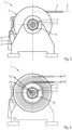
- Figs. 1-3 show an embodiment of a winch 1 according to the invention.
- the winch 1 may be mounted on a deck of a ship (not shown), for example a tug boat, but it may be mounted on any platform in an alternative application.
- the winch 1 comprises a frame 2, a drum 3 and a cable 4.
- the drum 3 is mounted to the frame 2 through two roller bearings 5 and is rotatable with respect to the frame 2 about an axis of rotation X.
- Each of the roller bearings 5 has an inner ring and an outer ring.
- opposite axial sides of the drum 3 are provided with shaft portions 12 onto which the inner rings of the roller bearings 5 are mounted, see Fig. 2A .
- the outer rings are fixed to the frame 2. It is noted that an alternative embodiment may have different types of bearings than roller bearings.
- the cable 4 is wound around the drum 3 and under operating conditions a part of the cable 4 extends outwardly from the drum 3 and lies in a cable plane P which extends tangentially with respect to the drum 3, see Figs. 1 and 3 .
- the cable 4 may have a plurality of layer numbers such that the height level of the cable plane P with respect to the axis of rotation X may vary under operating conditions. In the condition as shown in Fig. 3 the cable plane P extends horizontally. Under operating conditions the part of the cable 4 that extends outwardly from the drum 3 may lie in the cable plane P at different positions along the axis of rotation. It is also possible that the part of the cable 4 that extends outwardly from the drum 3 lies in the cable plane P by an acute angle to the axis of rotation X.
- the winch 1 is provided with a brake in the form of two friction bands 6 which partly surround respective circular cylindrical portions of the drum 3 located at different positions along the axis of rotation X.
- the friction bands 6 can be clamped about the cylindrical portions of the drum 3 through respective hydraulic cylinders 7 in order to reduce or stop rotation of the drum 3 with respect to the frame 2.
- the winch 1 comprises two brake rods 8, which are pivotally coupled to the frame 2 and to the respective friction bands 6. Upon activating the hydraulic cylinders 7 the drum 3 can be locked to the frame 2.
- Fig. 4 illustrates forces on the drum 3 under two different operating conditions.
- the brake holds the drum 3 at a fixed rotational position with respect to the frame 2, but in a first operating condition the cable 4 leaves the drum at a larger distance from the axis of rotation X than in a second operating condition due to the different layer numbers.
- the cable 4 exerts equal cable forces Fc1 and Fc2 on the drum 3, respectively. This results in different torques about the axis of rotation X because of the different distances from the axis of rotation X at which the cable 4 leaves the drum 3.
- the respective friction bands 6 exert a resultant counter torque by exerting a resultant counter force on the drum 3, which resultant counter force is directed downwardly in this case due to the arrangement of the brake.
- Fig. 4 illustrates that reaction force Fr1 in response to the cable force Fc1 in the first operating condition is not only larger than reaction force Fr2 in response to the cable force Fc2 in the second operating condition, but it has also a different angle with respect to the frame 2. Conversely, this provides the opportunity to derive the actual cable force Fc1 or Fc2 when the size and direction of the reaction force Fr1 or Fr2, respectively, is known, i.e. without knowing the distance from the axis of rotation X where the cable 4 leaves the drum 3.
- the frame 2 is provided with separate sensor rings 9 which surround the outer rings of the respective roller bearings 5, see Figs. 2, 2A , 3 and 4 . They may be sandwiched between the outer rings of the respective roller bearings 5 or they may be fixed to the frame 2, for example accommodated in a groove in the frame 2. It is also conceivable that the sensor rings 9 are accommodated in grooves in the outer rings of the respective roller bearings 5.
- Each of the sensor rings 9 comprises an optical fibre which accommodates a plurality of optical strain gauges 10 for determining local deformation of the area around the respective optical strain gauges 10.
- the optical strain gauges 10 are located at equiangular distances from each other about the axis of rotation X, but this may be different in an alternative embodiment.
- the sensor rings 9 at both roller bearings 5 are the same in this case, but they may be different in an alternative embodiment.
- Signals from the optical strain gauges 10 are processed by a data processor (not shown) to determine the resultant reaction force Fr1, Fr2 in order to derive the actual cable forces Fc1, Fc2.
- the step of data processing may comprise the step of determining a contact force vector using a mathematical model which describes the roller bearings 5.
- optical strain gauges may be replaced by alternative sensing probes, for example non-optical strain gauges, such as resistive foil strain gauges.
Landscapes
- Engineering & Computer Science (AREA)
- General Engineering & Computer Science (AREA)
- Mechanical Engineering (AREA)
- Physics & Mathematics (AREA)
- General Physics & Mathematics (AREA)
- Force Measurement Appropriate To Specific Purposes (AREA)
Priority Applications (1)
| Application Number | Priority Date | Filing Date | Title |
|---|---|---|---|
| EP23161717.6A EP4431441A1 (fr) | 2023-03-14 | 2023-03-14 | Treuil |
Applications Claiming Priority (1)
| Application Number | Priority Date | Filing Date | Title |
|---|---|---|---|
| EP23161717.6A EP4431441A1 (fr) | 2023-03-14 | 2023-03-14 | Treuil |
Publications (1)
| Publication Number | Publication Date |
|---|---|
| EP4431441A1 true EP4431441A1 (fr) | 2024-09-18 |
Family
ID=85640804
Family Applications (1)
| Application Number | Title | Priority Date | Filing Date |
|---|---|---|---|
| EP23161717.6A Withdrawn EP4431441A1 (fr) | 2023-03-14 | 2023-03-14 | Treuil |
Country Status (1)
| Country | Link |
|---|---|
| EP (1) | EP4431441A1 (fr) |
Citations (4)
| Publication number | Priority date | Publication date | Assignee | Title |
|---|---|---|---|---|
| EP1897840B1 (fr) * | 2006-08-31 | 2010-01-20 | ROTZLER GMBH & CO. KG | Treuil |
| US9103733B2 (en) * | 2009-12-04 | 2015-08-11 | Aktiebolaget Skf | Bearing monitoring using a fiber bragg grating |
| CN204917823U (zh) * | 2015-09-14 | 2015-12-30 | 平阳县鹏伟机械有限责任公司 | 加钢丝绳的刹车带装置 |
| WO2018197512A1 (fr) * | 2017-04-28 | 2018-11-01 | Dana Brevini S.P.A. | Treuil à structure simplifiée |
-
2023
- 2023-03-14 EP EP23161717.6A patent/EP4431441A1/fr not_active Withdrawn
Patent Citations (4)
| Publication number | Priority date | Publication date | Assignee | Title |
|---|---|---|---|---|
| EP1897840B1 (fr) * | 2006-08-31 | 2010-01-20 | ROTZLER GMBH & CO. KG | Treuil |
| US9103733B2 (en) * | 2009-12-04 | 2015-08-11 | Aktiebolaget Skf | Bearing monitoring using a fiber bragg grating |
| CN204917823U (zh) * | 2015-09-14 | 2015-12-30 | 平阳县鹏伟机械有限责任公司 | 加钢丝绳的刹车带装置 |
| WO2018197512A1 (fr) * | 2017-04-28 | 2018-11-01 | Dana Brevini S.P.A. | Treuil à structure simplifiée |
Similar Documents
| Publication | Publication Date | Title |
|---|---|---|
| EP2914540B1 (fr) | Système de contrôle pour câbles ou similaire | |
| CA2279609C (fr) | Dispositif pour affaiblir activement d'indesirables vibrations dans des rouleaux rotatifs; dispositif pour traiter une bande de materiau; particulierement une bande de papier ou de carton | |
| CN107883892B (zh) | 偏心计算方法、旋转编码器、机器人臂和机器人装置 | |
| US10048171B2 (en) | Method and apparatus for measuring tire ground contact properties | |
| WO2001023862A1 (fr) | Systeme permettant de controler les conditions de fonctionnement des roulements | |
| GB2033094A (en) | Measuring forces | |
| US4024755A (en) | Deflector roll for measuring and checking the flatness of sheet metal stretched in motion | |
| EP4431441A1 (fr) | Treuil | |
| US10983021B2 (en) | Action force detecting unit for rotary member | |
| GB2093991A (en) | Torque measurement apparatus | |
| US11940343B2 (en) | Bearing having a single optical sensing fiber for load sensing and bearing unit comprising combined bearings | |
| JP5638312B2 (ja) | 内輪へのひずみセンサ内蔵型転がり軸受の荷重分布測定方法及びその装置 | |
| US5537878A (en) | Strip flatness measuring device | |
| SE452060B (sv) | Anordning for metande av vridmoment | |
| DE102019216992A1 (de) | Lagereinheit mit zumindest zwei Arten von Messfühlern, die an einem Gehäuse befestigt sind | |
| CN107091708A (zh) | 一种具有张力检测功能的导缆器 | |
| US9494732B2 (en) | Transversal load insensitive optical waveguide, and optical sensor comprising a wave guide | |
| US6212960B1 (en) | Apparatus for measuring the flatness of a strip in movement | |
| JPH11344395A (ja) | 回転軸の変形検出方法および装置 | |
| JP2000042616A (ja) | 冷延薄板の圧延形状制御方法および圧延形状制御装置 | |
| GB2062257A (en) | Optical Torque-measuring Device | |
| EP0241280A2 (fr) | Rouleau de détermination de la forme d'un ruban métallique | |
| EP4321268B1 (fr) | Unité de rouleau de capteur | |
| US20230175904A1 (en) | Device equipped with an optical sensing element for sensing axial loads, notably for a bearing | |
| US10060767B2 (en) | Rotary apparatus |
Legal Events
| Date | Code | Title | Description |
|---|---|---|---|
| PUAI | Public reference made under article 153(3) epc to a published international application that has entered the european phase |
Free format text: ORIGINAL CODE: 0009012 |
|
| STAA | Information on the status of an ep patent application or granted ep patent |
Free format text: STATUS: THE APPLICATION HAS BEEN PUBLISHED |
|
| AK | Designated contracting states |
Kind code of ref document: A1 Designated state(s): AL AT BE BG CH CY CZ DE DK EE ES FI FR GB GR HR HU IE IS IT LI LT LU LV MC ME MK MT NL NO PL PT RO RS SE SI SK SM TR |
|
| STAA | Information on the status of an ep patent application or granted ep patent |
Free format text: STATUS: THE APPLICATION IS DEEMED TO BE WITHDRAWN |
|
| 18D | Application deemed to be withdrawn |
Effective date: 20250319 |