EP4431442A1 - Système de manutention, élévateur et procédé de levage de véhicules - Google Patents
Système de manutention, élévateur et procédé de levage de véhicules Download PDFInfo
- Publication number
- EP4431442A1 EP4431442A1 EP24159236.9A EP24159236A EP4431442A1 EP 4431442 A1 EP4431442 A1 EP 4431442A1 EP 24159236 A EP24159236 A EP 24159236A EP 4431442 A1 EP4431442 A1 EP 4431442A1
- Authority
- EP
- European Patent Office
- Prior art keywords
- actuator
- cylinder
- piston
- chamber
- supply line
- Prior art date
- Legal status (The legal status is an assumption and is not a legal conclusion. Google has not performed a legal analysis and makes no representation as to the accuracy of the status listed.)
- Withdrawn
Links
Images



Classifications
-
- B—PERFORMING OPERATIONS; TRANSPORTING
- B66—HOISTING; LIFTING; HAULING
- B66F—HOISTING, LIFTING, HAULING OR PUSHING, NOT OTHERWISE PROVIDED FOR, e.g. DEVICES WHICH APPLY A LIFTING OR PUSHING FORCE DIRECTLY TO THE SURFACE OF A LOAD
- B66F7/00—Lifting frames, e.g. for lifting vehicles; Platform lifts
- B66F7/10—Lifting frames, e.g. for lifting vehicles; Platform lifts with platforms supported directly by jacks
- B66F7/16—Lifting frames, e.g. for lifting vehicles; Platform lifts with platforms supported directly by jacks by one or more hydraulic or pneumatic jacks
- B66F7/20—Lifting frames, e.g. for lifting vehicles; Platform lifts with platforms supported directly by jacks by one or more hydraulic or pneumatic jacks by several jacks with means for maintaining the platforms horizontal during movement
-
- B—PERFORMING OPERATIONS; TRANSPORTING
- B66—HOISTING; LIFTING; HAULING
- B66F—HOISTING, LIFTING, HAULING OR PUSHING, NOT OTHERWISE PROVIDED FOR, e.g. DEVICES WHICH APPLY A LIFTING OR PUSHING FORCE DIRECTLY TO THE SURFACE OF A LOAD
- B66F7/00—Lifting frames, e.g. for lifting vehicles; Platform lifts
- B66F7/28—Constructional details, e.g. end stops, pivoting supporting members, sliding runners adjustable to load dimensions
-
- F—MECHANICAL ENGINEERING; LIGHTING; HEATING; WEAPONS; BLASTING
- F15—FLUID-PRESSURE ACTUATORS; HYDRAULICS OR PNEUMATICS IN GENERAL
- F15B—SYSTEMS ACTING BY MEANS OF FLUIDS IN GENERAL; FLUID-PRESSURE ACTUATORS, e.g. SERVOMOTORS; DETAILS OF FLUID-PRESSURE SYSTEMS, NOT OTHERWISE PROVIDED FOR
- F15B15/00—Fluid-actuated devices for displacing a member from one position to another; Gearing associated therewith
- F15B15/08—Characterised by the construction of the motor unit
- F15B15/14—Characterised by the construction of the motor unit of the straight-cylinder type
Definitions
- the present invention relates to a handling system, for example for column or underground lifts of vehicles, as well as a lift and a process of lifting vehicles.
- the present invention may find application in the automotive sector for the assistance or lifting of vehicles, for example cars, trucks and agricultural vehicles.
- These lifts may use two or more hydraulic cylinders connected, by means of a pump, to a tank containing oil to allow the displacement of a vehicle with respect to the ground; in detail, these lifts generally comprise a main cylinder directly supplied by the pump; the main cylinder is connected to one or more auxiliary cylinders by means of an oil circuit that allows the main cylinder to supply the auxiliary cylinder.
- the oil circuit of known lifts comprises also a discharge line which puts in communication each auxiliary cylinder with an atmospheric-pressure oil recovery tank; see for example patents n. JP3503825B2 and US 6 279 685 B1 , as well as the patent applications n. GB724273A and US4500071A .
- hydraulic actuators used for lift systems and/or directly on vehicles, constituted by a sleeve inside which it is slidingly movable a piston.
- the piston divides the internal volume of the sleeve into a first and a second chamber; the head of the piston is provided with one through opening which puts in communication the first and second chamber. See for example patent applications n. US 3 683 748 A and n. CN 213 899 442 U .
- the Applicant has detected how the known lifts have a complex and expensive structure, that requires also various maintenance interventions, resulting then improvable under different aspects.
- Object of the present invention is therefore to overcome at least one of the drawbacks and/or limitations of the previous solutions.
- An object of the present invention is to provide a handling system and a lift having a simple and compact structure, manufacturable then at low costs but that at the same time result structurally strong, capable of continuously, quickly and reliably carrying out the lifting of products, for example vehicles. It is also an object of the present invention to provide a handling system and a lift capable of operating effectively and safely, in particular capable of carrying out the lifting of products, for example vehicles, without damaging them or the components of the lift itself.
- an actuator (5) comprising:
- the piston (7) extends in thickness between a first and a second head surface (7a, 7b) respectively delimiting part of the first and second chamber (C1", C2").
- the through opening (8) extends between said first and second head surface (7a, 7b).
- the cylinder (6) comprises:
- the inner lateral surface (9a), together with the first and second surface (9b, 9c), defines an internal volume of the cylinder where the piston (7) is housed.
- the first head surface (7a) delimits, in cooperation with part of the inner lateral surface (9a) and the first surface (9b), the first chamber (C1").
- the second head surface (7b) delimits, in cooperation with part of the inner lateral surface (9a) and the second surface (9c), the second chamber (C2").
- the cylinder (6) extends between a first and a second end (6a, 6b) along an extension direction (D"). In a 9th aspect according to any one of the preceding aspects the cylinder (6) is free of through openings that allow the expulsion of working fluid from the second chamber (C2"). In a 10th aspect according to any one of the preceding aspects the cylinder (6) comprises an inlet (14) configured for allowing the passage of a working fluid in the first chamber (C1") (optionally the inlet of the working fluid in the cylinder and the outlet of said working fluid from the cylinder).
- the inlet (14) is defined on the inner lateral surface (9a) or on the first surface (9b) of the cylinder (6).
- the cylinder (6) has exclusively the inlet (14), which is configured for allowing the passage of a working fluid.
- the inlet (14) is placed at the first end (6a).
- the inlet (14) is configured for allowing the input of the working fluid in the cylinder (6) and the outlet of said working fluid from said cylinder (6), wherein said inlet (14) is in direct fluid communication with the first chamber (C1").
- the inlet (14) is the only passage of the cylinder (6) configured for allowing the working fluid to pass in and out through the cylinder (6).
- the second chamber (C2) is in fluid communication exclusively with the first chamber (C1") of the same cylinder (6).
- the piston (7) has an outer lateral surface (10), optionally at least partly countershaped to the cylinder (6).
- said outer lateral surface (10) of the piston (7) defines, in cooperation with the cylinder (6), optionally with the inner lateral surface (9a), a gap (11) which puts in fluid communication the first and the second chamber (C1", C2").
- the outer lateral surface (10) of the piston (7) connects the first and the second head surface (7a, 7b), optionally said outer lateral surface (10) is interposed between the first and the second head surface (7a, 7b).
- the outer lateral surface (10) of the piston (7) is entirely countershaped to the inner lateral surface (9a) of the cylinder (6).
- the piston (7) is free of sealing elements, for example a gasket, at the gap (11).
- the second chamber (C2") of the cylinder (6) is exclusively in fluid communication with the first chamber (C1") through the gap (11) and the through opening (8).
- the piston (7) is movable along a direction parallel to a/the extension direction (D') of the cylinder (6).
- the piston (7) is movable approaching and moving away with respect to the first and second surface (9b, 9c) of the cylinder (6) to allow a variation in terms of volume of the first and second chamber (C1", C2").
- the actuator (5) comprises a rod (12) partially housed in the second chamber (C2") and engaged to the piston (7).
- the rod (12) extends from the second head surface (7b) of the piston (7) and protrudes from the inner volume of the cylinder (6), optionally through the second surface (9c).
- the rod (12) is exclusively housed in the second chamber (C2") of the cylinder (6).
- the through opening (8) has a passage section between 50 mm 2 and 500 mm 2 .
- the passage section of the through opening (8) is constant throughout theta thickness of the piston (7).
- the piston (7) has, in cross section, a surface size between 100 mm 2 and 1500 mm 2 ; wherein the cross section is defined according to a plane orthogonal to a/the extension direction (D") of the cylinder (6).
- the ratio between the passage section of the at least one through opening (8) and the surface size of the piston (7) is between 0,01 and 0,2.
- the rod (12) has, according to a section orthogonal to a/the extension direction (D") of the cylinder (6), a surface size between 50 mm 2 and 1000 mm 2 .
- the ratio between the passage section of the through opening (8) and the surface size of the rod (12) is between 0,005 and 0,2.
- the ratio between the surface size of the piston (7) and the surface size of the rod (12) is between 1,1 and 3.
- the actuator (5) is of hydraulic or pneumatic type.
- a handling system (4) comprising:
- the secondary supply line (21) is exclusively in fluid communication (optionally directly) with the outlet (25) of the second actuator (22).
- the piston (27) of the first actuator extends in thickness between a first and a second head surface (27a, 27b) respectively delimiting part of the first and second chamber (C1', C2') of the cylinder (26) of the first actuator (22).
- the cylinder (26) of the first actuator (22) comprises:
- the inner lateral surface (29a), together with the first and second surface (29b, 29c), defines an internal volume of the cylinder (26) where it is housed the piston (27) of the first actuator (22).
- the first head surface (27a) of the piston (27) of the first actuator (22) delimits, in cooperation with part of the inner lateral surface (29a) and the first surface (29b), the first chamber (C1') of the first actuator (22).
- the second head surface (27b) of the piston (27) of the first actuator (22) delimits, in cooperation with part of the inner lateral surface (29a) and the second surface (29c), the second chamber (C2') of the first actuator (22).
- the first actuator (22) extends between a first and a second end (26a, 26b) along an extension direction (D').
- the first chamber (C1') of the cylinder (26) of the first actuator (22) is exclusively in fluid communication (optionally directly) with the primary supply line (20) through the inlet (24) of the first actuator (22).
- the second chamber (C2') of the cylinder (26) of the first actuator (22) is exclusively in fluid communication (optionally directly) with the secondary supply line (21) through the outlet (25) of the first actuator (22).
- the piston (27) of the first actuator (22) has an outer lateral surface (30) at least partly countershaped to the cylinder (26) of the first actuator (22).
- the first actuator (22) has at least one sealing element (28) interposed between said outer lateral surface (30) of the piston (27) and the inner lateral surface (29a) of the cylinder (26) of the first actuator (22), said sealing element (28) being configured for preventing a fluid passage between the first and the second chamber (C1', C2') of the cylinder (26) of the first actuator (22).
- the piston (27) of the first actuator (22) is movable along a direction parallel to a/the extension direction (D') of the cylinder (26) of the first actuator (22).
- the piston (27) of the first actuator (22) is movable approaching and moving away with respect to the first and second surface (29b, 29c) of the cylinder (26) to allow a variation in terms of volume of the first and second chamber (C1', C2') of the first actuator (22).
- the first actuator (22) comprises a rod (32) partially housed in the second chamber (C1') and engaged to the piston (27) of the first actuator (22).
- the rod (32) of the first actuator (22) extends from the second head surface (27b) of the piston (27) and protrudes from the inner volume of the cylinder (26) through the second surface (29c).
- the rod (22) is exclusively housed in the second chamber (C2') of the first actuator (22).
- the rod (22) does not pass through the first chamber (C1') of the first actuator (22).
- the supply circuit comprises:
- the primary supply line (20) comprises:
- the supply circuit comprises a pump (33) active on the primary supply line (20), optionally on the first section (13), and configurable between:
- the handling system comprises a control unit (50) operatively connected to the pump (33) and configured for commanding the activation condition and the deactivation condition of the pump (33).
- the supply circuit comprises a bypass line (34) which puts in fluid communication the primary supply line (20), optionally the second section (23), with the secondary supply line (21).
- the supply circuit comprises a balance valve (35) active on the bypass line (34) and configurable between:
- the supply circuit comprises a first pressure sensor (36) connected to the primary supply line (20), optionally to the second section (23), and configured for generating a signal representative of the fluid pressure upstream of the balance valve (35).
- the supply circuit comprises a second pressure sensor (37) connected to the secondary supply line (21) and configured for generating a signal representative of the fluid pressure downstream of the balance valve (35).
- theta control unit (50) is operatively connected to the first and second pressure sensor (36, 37) and configured for:
- control unit (50) is configured for:
- control parameter is representative of a difference of pressure between the primary supply line (20) and the secondary supply line (21).
- control unit (50) is configured for commanding the opening position of the balance valve (35) if one or more pressure values of the control parameter are higher than the threshold value.
- the supply circuit comprises a parachute valve (44) sensitive to a variation of pressure of the working fluid on the primary supply line (20) upstream of the inlet (24) of the first actuator (22).
- the parachute valve (44) is configurable between:
- the parachute valve (44) is configured for passing from the opening condition to the closing condition if an increase of the working flow is detected in the primary supply line (20), optionally creating a pressure variation between an upstream and a downstream section of the parachute valve itself higher than a predefined threshold value, for example between 5 bar and 20 bar.
- the supply circuit comprises a return line (38) which puts in fluid communication the second section (23) of the primary supply line (20) with the source (S).
- the supply circuit comprises a discharge valve (41) active on the return line (38) and configurable between:
- theta control unit (50) is active on the discharge valve (41) and configured for commanding the closing position and the opening position.
- the supply circuit comprises a safety line (42) which puts in fluid communication the first section (13) of the primary supply line (20) with the source (S).
- the supply circuit comprises an overpressure valve (43) active on the safety line (42) and configured for allowing selectively the passage of fluid through the safety line (42) as a function of a pressure of the working fluid in the first section (13) of the primary supply line (20).
- theta control unit (50) is operatively connected to the overpressure valve (43) and is configured for:
- a lift (1) of vehicles comprising:
- the lift comprises at least one lifting arm carried by the at least one carriage.
- the at least one lifting arm is configured for contacting a vehicle, optionally the body of the vehicle, for allowing its lifting.
- the at least one carriage comprises:
- the first actuator (22) is housed in the first column (2').
- the second actuator (5) is housed in the second column (2").
- the first carriage (3') carried by the first column (2') is engaged to the first actuator (22), optionally to the rod (32) or to the cylinder (26) of the first actuator (22).
- the second carriage (3" carried by the second column (2") is engaged to the second actuator (5), optionally to the rod (12) or to the cylinder (6) of the second actuator (5).
- each of said first and second carriage comprises at least one respective lifting arm, optionally a pair of connection arms hinged to the carriage, even more optionally rotatable with respect to the carriage.
- each column extends between a respective base (2a', 2a") and a respective top (2b', 2b").
- the first and the second actuator (22, 15) are respectively placed at their respective bases (2a', 2a") of the first and of the second column (2', 2").
- each frame, respectively of the first and of the second column (2', 2", has, along its entire extension, a constant-profile transversal section, optionally having a substantially "C"-shaped profile.
- the frame of the first column (2') comprises:
- the frame of the second column (2") comprises a respective access (49) near the top (2b") of the second column (2"), configured for allowing the inlet of the secondary supply line (21) in the space (V) of the second column (2").
- the secondary supply line (21) extends at least partly in the spaces of the frame of the first and second column.
- the secondary supply line extends also at least partly outside the frames of the first and second column, optionally said secondary supply line, in use, extends at least partly above the columns.
- the lift comprises a user interface (Ul) manually operated by a user and configured for:
- theta control unit (50) is connected to the user interface (Ul) and is configured for:
- the process comprises the following steps:
- the step of supplying working fluid comprises the sub-step of activating the pump (33) of the supply circuit for displacing said at least one carriage along the first and second column (2', 2") moving away from the ground.
- the step of activating the pump (33) provides the steps of:
- the step of moving fluid from the first actuator (22) to the second actuator (5) provides the sub-steps of:
- part of the working fluid passes from the second to the first chamber (C2", C1") of the cylinder (6) of the second actuator (5).
- the step of moving working fluid from the second to the first chamber of the second actuator (5) provides the sub-step of:
- a step of balancing comprises the sub-steps of:
- step of balancing provides for commanding the opening position of the balance valve (35) if one or more pressure values of the control parameter are higher than the threshold value.
- a safety procedure comprising a step of moving fluid along the safety line (42) as a function of a value of pressure of the fluid in the first section (13) of the primary supply line (20).
- the step of the safety procedure of moving fluid along the safety line (42), comprises the sub-steps of:
- the process comprises the steps of:
- the step of arranging the discharge valve (41) in opening position allows the working fluid to:
- the working fluid passes, also, from the first to the second chamber (C1", C2") of the second actuator (5) through the through opening (8) of the piston (7), optionally through the gap (11) of the second actuator (5).
- vertical and horizontal used in relation to components of the lift, refer to a condition of its use during which the lift carries out, or is usable for, a lifting/lowering procedure of a vehicle with respect to the ground.
- the handling system and/or the lift described and claimed below may comprise/use at least one control unit in charge of the control of the operating conditions put in place by the lift itself and/or to the control of the steps of the process of lifting of a vehicle.
- the control unit may be a single unit or be formed by a plurality of distinct control units depending on design choices and operational requirements. With control unit it is intended an electronic type component which may comprise at least one among: a digital processor (CPU), an analogue type circuit, or a combination of one or more digital processors with one or more analogue type circuits.
- the control unit may be " configured " or " programmed " to perform certain steps: this may be realized in practice with any means that allow to configure or program the control unit.
- one or more programs may be stored in appropriate memory banks connected to the CPU or CPUs; the program or programs contain instructions which, when performed by the CPU or CPUs, program or configure the control unit to perform the operations described in relation to the control unit.
- the control unit is or comprises analogue type circuitry, the circuit of the control unit may be then designed to include circuitry configured, in use, for processing electrical signals so as to perform the steps relative to the control unit.
- Parts of the described process may be realized by means of a data processing unit or control unit, technically replaceable with one or more computers designed to carry out a portion of a software program or firmware loaded onto a storage medium.
- This software program may be written in any known programming language.
- the electronic processors if equal to two or more in number, may be connected to each other by means of a data connection such that their computing powers are shared in any way whatsoever; the same electronic processors may thus be installed in even geographically different locations, realizing through the above-mentioned data connection a distributed computing environment.
- the data processing unit, or control unit may be a general-purpose processor configured for carrying out one or more parts of the process identified in the present disclosure through the software or firmware program, or be an ASIC or dedicated processor or FPGA, specifically programmed to carry out at least part of the operations of the process described herein.
- the storage medium may be non-transitory and may be internal or external to the processor, or control unit, or data processing unit, and may - specifically - be a memory geographically located remote with respect to the electronic processor.
- the storage medium may also be physically divided into multiple portions, or in the form of a cloud, and the software or firmware program may physically provide for portions stored on geographically divided portions of memory between them.
- the actuator 5 may be of pneumatic type using as working fluid a gas, for example air, or of hydraulic type, using a hydraulic oil.
- the actuator 5 has a cylinder 6 comprising a hollow body extending longitudinally along an extension direction D" between a first and a second end 6a, 6b.
- the cylinder 6 comprises an inner lateral surface 9a which connects a first surface 9b - defining, in use, an inner base surface of the actuator 5 - with a second surface 9c opposite to the first surface 9b, defining, in use, an inner top surface of the cylinder 6.
- the inner lateral surface 9a together with the first and to the second surface 9b, 9c, delimit the space of the cylinder 6 having a predetermined inner volume.
- the inner lateral surface 9a has, according to a section orthogonal to the extension direction D", a circular shape; consequently, the first and the second surface 9b, 9c, placed at the end of the inner lateral surface 9a, have a circular shape.
- the inner lateral surface 9a defines a passage section between 100 mm 2 and 1500 mm 2 , optionally between 100 mm 2 and 1400 mm 2 ; this passage section is measured according to a plane orthogonal to the extension direction D" of the cylinder 6.
- the inner lateral wall 9a has a length, measured along the extension direction D" higher than 150 mm, optionally between 500 mm and 3000 mm. Actually, the length of the inner lateral surface 9a is defined by the distance present between the first and the second surface 9b, 9c which substantially coincides with the length of the cylinder 6.
- a piston 7 slidingly movable along the extension direction D" approaching and moving away with respect to the first and second surface 9b, 9c.
- the cylinder 6 may comprise an inlet 14 defined on the inner lateral surface 9a at the first end 6a, or on the first surface 9b, for allowing the passage of the working fluid from or to the inner volume of the cylinder 6: the inlet 14 defines the only opening of the cylinder 6 that allows the passage of the working fluid: the cylinder 6 is free of additional openings or accesses defined on the inner lateral surface 9a or on the first or second surface 9b, 9c, which allow the passage of the working fluid.
- the cylinder 6 has however an auxiliary opening, optionally with a circular section, defined on the second surface 9b of the cylinder 6, which allows exclusively the passage of a rod 12 of the piston 7.
- the cylinder 6 comprises furthermore a gasket, for example an O-ring, engaged at the auxiliary opening of the cylinder 6; the gasket is countershaped to the rod 12 of the piston 7 and configured for allowing the sliding of said rod 12 with respect to the gasket itself, avoiding substantially the passage of the working fluid, avoiding so the leakage of said working fluid from the space of the cylinder 6. Excluding the inlet 14, the cylinder 6 is therefore free of additional openings that allow the passage of fluid through the cylinder 6.
- the actuator 5 comprises a piston 7.
- the piston 7 divides the inner volume of the cylinder 6 in a first and a second chamber C1", C2", which show a variable volume, as a function of the position of the piston 7 in relation to the cylinder 6.
- the piston 7 is delimited in thickness by a first and a second head surface 7a, 7b, respectively faced to the first and the second end 6a, 6b of the cylinder 6 and delimiting at least partly, the first and the second chamber C1", C2".
- the first head surface 7a delimits, in cooperation with part of the inner lateral surface 9a and the first surface 9b of the cylinder 6, the first chamber C1", while the second head surface 7b delimits, in cooperation with part of the inner lateral surface 9a and the second surface 9c of the cylinder 6, the second chamber C2".
- the piston 7 has, in cross section, a surface size between 100 mm 2 and 1500 mm 2 ; wherein the cross section is defined according to a plane orthogonal to the extension direction D" of the cylinder 6.
- the thickness of the piston 7 is defined by the maximum distance present between said first and second head surface 7a, 7b; in terms of size, the ratio between the thickness of the piston 7 and the length of the inner lateral surface 9a of the cylinder 6 is between 0,01 and 0,3, optionally between 0,01 and 0,1.
- the piston 7 has also an outer lateral surface 10 interposed between the first and the second head surface 7a, 7b and delimiting perimetrically the piston itself.
- the outer lateral surface 10 of the piston 7 connects the first and second head surface 7a, 7b and defines the surface size of the piston 7.
- the outer lateral surface 10 is at least partly, optionally entirely, countershaped to the inner lateral surface of the cylinder 6.
- the outer lateral surface 10 of the piston 7 may have an outer perimeter having a substantially circular shape, entirely countershaped to the inner lateral surface 9a.
- the outer lateral surface 10 of the piston has, in section, a smaller size with respect to the passage section defined by the inner lateral wall 9a of the cylinder; in detail, the smaller size of the outer lateral surface 10 with respect to the inner lateral surface 9a of the cylinder allows to define, between said surfaces, a gap 11 which allows to put in fluid communication the first and the second chamber C1", C2".
- the piston 7 is free of sealing elements, for example gaskets, housed in the gap 11 to prevent an exchange of working fluid between the first and the second chamber C1", C2".
- the piston 7 has also at least one through opening 8 which extends between the first and the second head surface 7a, 7b: the through opening 8 extends thus for the whole thickness of the piston 7 and is configured for putting in fluid communication the first and the second chamber C1", C2".
- the at least one through opening 8 may be defined at a radially inner zone of the piston spaced from the outer lateral surface 10, optionally interposed between the outer lateral surface 10 and the rod 12; in this condition, the through opening 8 is delimited by a closed perimeter, for example having circular shape.
- the through opening 8 would have an open type perimeter, for example having an arcuate shape, essentially defining, on the outer lateral surface 10 of the piston 7, one or more recesses.
- the possibility of one two or more of said through openings 8 spaced from the outer lateral surface 10 of the piston 7 and one or more of said through openings 8 defined on the outer lateral surface (i.e. to define recesses of the outer lateral surface 10) is not excluded.
- the at least one through opening 8 may have a constant passage section, between 50 mm 2 and 500 mm 2 .
- passage section it is intended the section defined by the at least one passage opening 8; if there are two or more through openings 8, this passage section is intended as the sum of the passage sections of all the through openings 8.
- this passage section is intended as the sum of the passage sections of all the through openings 8.
- the surface size of the piston 7 is higher than the passage section of the through opening 8; in detail, the ratio between the passage section of the through opening 8 and the surface size of the piston 7 the surface size of the piston and the passage section of the through opening 8 may be between 0,01 and 0,2; with surface size of the piston 7 it is intended the maximum area defined by the outer lateral surface 10 of the piston 7.
- the through opening 8 and the gap 11 define thus respective passages which put in fluid communication the first and the second chamber C1", C2" for allowing, during the handling of the rod 12 in the cylinder 6 the passage of the working fluid from the first to the second chamber C1", C2".
- the actuator 5 comprises a rod 12 partially housed in the second chamber C2" and engaged to the piston 7.
- the rod 12 extends from the second head surface 7b of the piston 7, externally to the cylinder 6 passing through the auxiliary opening defined on the second end 6b of the cylinder 6. Therefore, the rod 12 is exclusively housed in the second chamber C2", without passing through the first chamber C1".
- the rod 12 has an elongated body, optionally of cylindrical shape, which, according to a section orthogonal to the extension direction D" of the cylinder 6, has a surface size between 50 mm 2 and 1000 mm 2 .
- the surface size of the piston 7 is higher than the surface size of the rod 12; in greater detail, the dimensional ratio between the surface size of the piston 7 (maximum area defined by the outer lateral surface 10) and the surface size of the rod 12 is between 1,1 and 10. Furthermore, the ratio between the passage section of the through opening 8 (optionally the passage section defined by all of the through openings 8 present on the piston 7) and the surface size of the rod 12 may be between 0,005 and 0,2.
- the second head surface 7b has a surface extension (i.e. the area defined by the surface 7b) smaller than the surface extension of the first head surface 7a.
- the sum of the surface extension of the second head surface 7b and the surface size of the rod 12 define substantially the same surface extension of the first head surface 7a.
- the ratio between the surface extension of the first head surface and the surface extension of the second head surface may be between 1,05 and 1,25.
- the actuator 5 allows the input of the working fluid in the first chamber C1" (input which may occur exclusively through the inlet 14, unique opening of passage for the working fluid entering and exiting the actuator 5) and the consequent displacement of the piston 7 approaching to the second surface 9c of the cylinder 6; during the input of the working fluid in the first chamber C1", the through opening 8 (or the plurality of openings 8) puts in fluid communication the first chamber C1" and the second chamber C”: the through opening 8 ensures thus that the working fluid present in said first and second chamber C1", C2" has substantially the same pressure.
- a handling system 4 for example for lifts of vehicles, comprising a first actuator 22 and a second actuator 5 according to the above-described actuator 5.
- the first actuator 22 may be a double-effect pneumatic or hydraulic actuator.
- the first actuator 22 comprises a cylinder 26 whose structure is similar to the one of the above-described cylinder 6 for the actuator 5, i.e. the second actuator 5.
- the cylinder 26 of the first actuator is hollow and longitudinally extending along an extension direction D' between a first and a second end 26a, 26b.
- the cylinder 26 of the first actuator comprises an inner lateral surface 29a that connects a first surface 29b - defining, in use, an inner base surface of the first actuator 22 - with a second surface 29c opposite to the first surface 29b, defining, in use, an inner top surface of the cylinder 26.
- the inner lateral surface 29a has, according to a section orthogonal to the extension direction D', a circular shape; consequently, the first and the second surface 29b, 29c, placed at the end of the inner lateral surface 29a, have a circular shape.
- the inner lateral surface 29a defines a passage section which may be between 100 mm 2 and 1500 mm 2 ; this passage section is measured according to a plane orthogonal to the extension direction D' of the cylinder 26 of the first actuator.
- the inner lateral wall 29a has a length, measured along the extension direction D' higher than 150 mm, optionally between 500 mm and 3000 mm. In fact, the length of the inner lateral surface 29a is defined by the distance present between the first and the second surface 29b, 29c which substantially coincides with the length of the cylinder 26 of the first actuator 22.
- the cylinder 26 of the first actuator 22 may be substantially identical in shape and in size to the cylinder 6 of the second actuator 5. Also in the space of the cylinder 26 of the first actuator 22 it is housed a piston 27 slidingly movable along the extension direction D' of the cylinder 26 approaching and moving away with respect to the first and second surface 29b, 29c.
- the cylinder 26 may comprise an inlet 24 defined on the inner lateral surface 29a at the first end 26a, or on the first surface 29b, for allowing the passage of the working fluid from or toward the inner volume of the cylinder 26: the inlet 24 defines an opening of the cylinder 26 which allows the passage of the working fluid.
- the cylinder 26 of the first actuator 22 may furthermore comprise an outlet 25, spaced from the inlet 24 and defined on the inner lateral surface 29a, at the second end 26b, or on the second surface 29c; the outlet 25 defines too one through opening configured for allowing the passage of the working fluid from or toward the inner volume of the cylinder.
- the cylinder 26 has also an auxiliary opening, optionally with circular section, defined on the second surface 29b of the cylinder 26, which allows exclusively the passage of a rod 32 of the piston 27.
- the cylinder 26 of the first actuator 22 comprises furthermore a gasket, for example an O-ring, engaged at the auxiliary opening of the cylinder 26; the gasket is countershaped to the rod 32 of the piston 27 and configured for allowing the sliding of said rod 32 with respect to the gasket itself, substantially preventing the passage of the working fluid, thus avoiding the leakage of said working fluid from the space of the cylinder 26.
- the cylinder 26 of the first actuator 22 comprises two through openings (the inlet 24 and the outlet 25) which allow the passage of the working fluid for the input and leakage of the working fluid from the cylinder 26.
- the first actuator 22 comprises a piston 27.
- the piston 27 divides the inner volume of the cylinder 26 of the first actuator 22 in a respective first and second chamber C1', C2', which have a variable volume, as a function of position of the piston 27 relative to the cylinder 26.
- the piston 27 of the first actuator 22 is delimited in thickness a first and a second head surface 27a, 27b, respectively faced to the first and to the second end 26a, 26b of the cylinder 26 of the first actuator 22 and delimiting at least partly, the first and the second chamber C1', C2'.
- the first head surface 27a delimits, in cooperation with part of the inner lateral surface 29a and the first surface 29b of the cylinder 26, the first chamber C1'
- the second head surface 27b delimits, in cooperation with part of the inner lateral surface 29a and the second surface 29c of the cylinder 26, the second chamber C2'.
- the piston 27 has, according to a section orthogonal to the extension direction D' of the cylinder 26, a surface size between 100 mm 2 and 1000 mm 2 .
- the thickness of the piston 27 is defined by the maximum distance present between said first and second head surface 27a, 27b; in terms of size, the ratio between the thickness of the piston 27 and the length of the inner lateral surface 29a of the cylinder 6 is between 0,01 and 0,3, optionally between 0,01 and 0,1.
- the piston 27 has also an outer lateral surface 30 which extends between the first and the second head surface 27a, 27b, perimetrally delimiting the piston itself.
- the outer lateral surface 30 of the piston 27 connects the first and second head surface 27a, 27b and defines the surface size of the piston 27.
- the outer lateral surface 30 is at least partly, optionally entirely, countershaped to the inner lateral surface of the cylinder 26.
- the outer lateral surface 30 of the piston 27 may have an outer perimeter having substantially circular shape, entirely countershaped to the inner lateral surface 29a.
- the outer lateral surface 30 of the piston has, in cross section, a lower size with respect to the passage section defined by the inner lateral wall 29a of the cylinder; in detail, the smaller size of the outer lateral surface 30 with respect to the inner lateral surface 29a of the cylinder allows to define, between said surfaces, a gap 11 in which it is housed at least one sealing element 28: the sealing element 28 is interposed between the outer lateral surface 30 of the piston 27 and the inner lateral surface 29a of the cylinder 26 of the first actuator 22, in such a way as to prevent a passage of fluid between the first and the second chamber C1', C2' of the cylinder 26 of the first actuator 22.
- the first and the second chamber C1', C2' of the first actuator 22 are between them isolated, resulting exclusively in fluid communication respectively with the inlet 24 and the outlet 25 of the cylinder 26 of the first actuator 22.
- the piston 27 of the first actuator 22 is free of through openings capable of putting in fluid communication the first and the second chamber C1', C2' of the cylinder 26.
- the first actuator 22 comprises also a rod 32 partially housed in the second chamber C2' and engaged to the piston 27.
- the rod 32 extending from the second head surface 27b of the piston 27, externally to the cylinder 26 passing through the auxiliary opening defined on the second end 26b of the cylinder 26. Therefore, the rod 32 is exclusively housed in the second chamber C2' of the cylinder 26 of the first actuator 22, without passing through the first chamber C1'.
- the rod 32 has an elongated body, optionally of cylindrical shape, which, according to a section orthogonal to a/the extension direction D' of the cylinder 26, has a surface size between 50 mm 2 and 1000 mm 2 .
- the first and second actuator may be identical in terms of size, i.e. have an internal volume of the cylinder, a size of the piston and of the rod having the same size. As it may be seen from the above-mentioned description, the first and second actuator differ in that:
- the handling system 4 may comprise a supply circuit for the first and second actuator 22, 5.
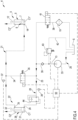
- the supply circuit comprises a primary supply line 20 configured for putting in fluid communication the inlet 24 of the first actuator 22 with a source S of a working fluid, for example defined by a tank configured for containing a predetermined quantity of working fluid, as well as a secondary supply line 21 which puts in fluid communication the outlet 25 of the first actuator 22 with the inlet 14 of the second actuator 5.
- the handling system 4 may comprise a non-return valve 39 active on the primary supply line 20, configured for preventing the passage of fluid toward the source S.
- the non-return valve 39 defines a first section 13 of the primary supply line 20 interposed between the source S and the non-return valve 39 and a second section 23 of the primary supply line 20, interposed between the non-return valve 39 and the inlet 24 of the first actuator 22.
- the supply circuit may comprise a pump 33 active on the first section 13 of the primary supply line, configurable between an active condition wherein it moves the working fluid accessing to the first actuator 22 and a deactivated condition wherein it does not act on the working fluid.
- the pump 33 is configured for moving the working fluid from the source S, through the non-return valve 39, accessing to the cylinder 26 of the first actuator through the inlet 24.
- the pump 33 is in the active condition if there is a need to lift a vehicle through the lift 1, vice versa, the pump 33 is in the deactivated condition in case of lowering of the vehicle.
- the handling system 4 may comprise a control unit 50 operatively connected to the pump 33 and configured for commanding the activation and deactivation conditions of the pump 33 on the base of commands inserted by a user through a subsequently described UI user interface.
- the supply circuit may comprise a parachute valve 44 active on the second section 23 of the primary supply line 20 and sensitive to a pressure variation and/or flow rate of the working fluid in the second section 23, i.e. upstream of the inlet 24 of the first actuator 22.
- the parachute valve 44 if it is detected an undesirable increase of pressure and/or of flow rate of the working fluid in the second section 23 is configured for passing from an opening condition (condition of normal operation of the handling system) to a closing condition in which the valve 44 prevents the passage of working fluid.
- the parachute valve 44 allows to prevent the uncontrolled descent of the first and of the second actuator 22, 5 in case of breakage of the primary supply line 20 or of the secondary supply line 21, providing the passage of working fluid in the second section 23 of the primary supply line 20.
- the described parachute valve 44 is a purely mechanical valve, capable of operating without the aid of electronic devices.
- an electronically controlled valve for example an electromechanical valve of known type, appropriately controlled from the control unit 50 as a function of a measurement of a value of pressure and/or flow rate of the working fluid sampled by a sensor active on the primary supply line 20 is not excluded.
- the supply circuit may comprise a bypass line 34 which puts in fluid communication the second section 23 of the primary supply line 20 with the secondary supply line 21, as well as a balance valve 35 active on the same bypass line, which is configured for compensating an eventual pressure difference between the primary and secondary supply line 20, 21.
- the balance valve 25 is thus configurable between opening and closing conditions, wherein respectively allows and prevents the passage of working fluid on the bypass line 34, as a function of a pressure gap.
- the handling system 4 may comprise a first and a second pressure sensor 36, 37 respectively active on the second section 23 of the primary supply line 20 and on the secondary supply line 21, configured for generating signals representative of the pressure of the working fluid present in the respective supply lines.
- the control unit 50 is operatively connected to the first and to the second pressure sensor 36, 37, configured for receiving the pressure signals emitted by each sensor and determining one or more measured values of pressure of the working fluid, respectively in the second section 23 of the primary supply line 20 and in the secondary supply line 21.
- the control unit 50 is then configured for commanding the balance valve 35 as a function of one or more values of a control parameter.
- the control unit 50 is configured for:
- the supply circuit may furthermore comprise a discharge line 38 which puts in fluid communication the second section 23 of the primary supply line 20 with the source S, as well as a discharge valve 41 active on the same discharge line 38, for allowing the passage of fluid toward the source S as a function of a command entered by a user.
- the discharge valve 41 is thus configurable between respective opening and closing conditions wherein respectively allows and prevents the passage of working fluid along the discharge line 38.
- the control unit 50 is operatively connected to the discharge valve 41 and is configured for commanding it during the opening or closing as a function of a command entered by a user through the user interface Ul.
- the discharge valve 41 is in the opening condition if there is a need to lower a vehicle through the lift 1 ( figure 5 ), while it is in the closing condition in case of lifting of the vehicle ( figure 4 ).
- the control unit 50 is thus configured for commanding in an asynchronous way the discharge valve 41 and the pump 33, in such a way that to the activation condition of the pump 33 corresponds the closing condition of the discharge valve 41 and, vice versa, to the deactivation condition of the pump 33 corresponds the opening condition of the discharge valve 41.
- the supply circuit may also comprise a filter 14 active on the discharge line 38 for filtering the working fluid accessing the source S.
- the supply circuit may furthermore comprise a safety line 42 which puts in fluid communication the first section 13 of the primary supply line 20 with the source S, as well as an overpressure valve 43 active on the same safety line 42, for allowing the passage of fluid toward the source S if the pressure of the working fluid in the first section 13 is higher than a predetermined reference value.
- the overpressure valve 43 may be of a fully mechanical type, capable of passing from a closing condition to an opening condition if it detects and determines pressure values of the working fluid in the first section 13 higher than the reference value.
- the overpressure valve 43 may be opportunely connected and commanded by the control unit 50, which would be configured for:
- the handling of the piston 27 of the first actuator 22 determines the handling of the working fluid present in the second chamber C2' of the cylinder 26 and of the working fluid present in the secondary supply line 21, toward the cylinder 6 of the second actuator and in particular the input of working fluid in the first chamber C1" of the second actuator 5 through the inlet 14.
- the inlet of the working fluid in the first chamber C1" allows to displace the piston 7 toward the second surface 9c of the cylinder 6.
- the second actuator 5 allows the input of the working fluid in the first chamber C1" (input that exclusively occurs through the inlet 14) and the subsequent displacement of the piston 7 approaching to the second surface 9c of the cylinder 6; during the input of the working fluid in the first chamber C1", the through opening 8 puts in fluid communication the first chamber C1" and the second chamber C”: the through opening 8 ensures thus that the working fluid present in said first and second chamber C1", C2" have substantially the same pressure.
- the piston 7, in the step of input the working fluid in the first chamber C1" may be displaced toward the second end 6b of the cylinder;
- the first head surface 7a precisely thanks to its surface extension greater with respect to the second head surface, allows to generate (at equal pressure of the working fluid present in the first and second chamber C1", C2") a thrust on the piston 7 greater than the one that may be generated from the second head surface 7b.
- the working fluid during the handling of the piston 7 approaching to the second end 6b, may flow through the at least one through opening 8 for passing from the second chamber C2" to the first chamber C1".
- the pump 33 While instead the pump 33 is in the deactivated condition and the discharge valve 41 is in the opening condition, it is obtained the handling of the working fluid toward the source; in particular, the working fluid present on the secondary supply line 21, moves from the cylinder 6 of the second actuator 5 toward the cylinder 26 of the first actuator 22, accessing the second chamber C2' through the outlet 25, the working fluid present on the primary supply line 20 moves from the cylinder 26 of the first actuator 22, exiting from the inlet 24 and along the discharge line 38, toward the source S.
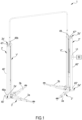
- the lift 1 may comprise a first and a second column 2', 2" between them spaced and extending, in use, along a vertical direction between a respective base 2a', 2a" and a respective top 2b', 2b".
- the columns define the supporting vertical element of the lift 1, configured for supporting a hanging vehicle with respect to the ground; the columns 2 are fixable to the ground, for example by means of screw-bolt systems.
- the first column 2' may comprise a base plate 45', optionally in metallic material, configured for being fixed to the ground and from which protrudes, for the whole extension of the first column, a frame 46'.
- the base plate 45' of the first column 2' may comprise a plurality of holes configured for receiving a screw to fasten the base plate 45' and consequently the entire first column 2', to the ground.
- the frame 46' of the first column 2' is engaged to the base plate 45' and has, along its whole extension, a "C" or "V" shaped constant profile transversal section defining within it a space V'.
- the frame 46 is realized through one or more layers of sheet metal in metallic material.
- the first actuator 22 of the handling system 4 In the space V' of the first column is housed the first actuator 22 of the handling system 4.
- the first actuator 22 is fixed to the frame 46' and/or to the base plate 45' of the first column 2', at the base 2a'.
- the first end 26a of the cylinder 26 of the first actuator is placed near the base 2a' of the first column; the piston 27, along with to the rod 32 of the first actuator 22 are configured for moving approaching and moving away with respect to the top 2b'.
- the part of rod 32 of the first actuator that protrudes from the cylinder 26 results faced to the top 2b', spaced from the base 2a' (see for example the diagram of figure 2 ).
- the second through access 48b allows to the secondary supply line 21 to connect to the outlet 25 of the cylinder 26 of the first actuator 22 and to exit from the space V' of the first column 2' for reaching the second column 2".
- a secondary supply line placed, at least for a section, above the columns 2', 2"; in this it is possible to avoid the positioning of the secondary supply line 21 at the ground where it could be more subject to damages causable by the passage of the vehicle and thus to breakages of the entire lift.
- the possibility of providing a passage of such secondary supply line 21 at the ground, for example by arranging a sub-passage for such a line that connects at the base of the two columns is not excluded.
- the second column 2" has a structurally identical structure to the first column 2'.
- the second column 2" comprises a base plate 45" configured for being fixed to the ground and from which protrudes a frame 46".
- the base plate 45" of the second column 2 comprises a plurality of holes configured for receiving a screw to fix the base plate 45" and consequently the entire second column 2", to the ground.
- the frame 46" of the second column 2" is engaged to the base plate 45" and has, along its whole extension, a "C” or "V” shaped constant profile transversal section, defining within it a space V" in which it is housed the second actuator 5.
- the second actuator 5 is fixed to the frame 46" and/or to the base plate 45" of the second column 2".
- the frame 46" of the second column 2" has also a top plate 47", opposite to the base plate 45", that vertically delimits the second column 2".
- the frame 46" of the second column 2" comprises a respective access 49, for example defined on the top plate 47" of the second column 2", configured for allowing the inlet of the secondary supply line 21 in the space V of the second column 2" for engaging to the inlet 14 of the second actuator 5. It should be noted how the secondary supply line 21 is housed, partly externally to the frames 46', 46" of the first and second column 2, 2" and partly inside the spaces V', V" of the respective frames 46', 46" of the first column and second column 2', 2".
- the carriage may comprise a first and a second lifting arm 3a, 3b ( figure 1 ) both configured for contacting a vehicle, optionally the body of the vehicle, for allowing its lifting.
- the lifting arms 3a, 3b lie substantially on a single plane orthogonal to the extension direction E of the column. At least one of said lifting arms may be of swiveling type, i.e. movable by rotation around a respective axis parallel to the extension direction of the column.
- each lifting arm 3a, 3b may carry at its end a supporting foot configured for directly contacting the body of the vehicle; in particular, the first and second arm 3a, 3b carry respective height-adjustable feet.
- the lift 1 may comprise a user interface Ul ( figure 1 ) manually operable by a user and configured for:
- the control unit 50 of the handling system 4 is connected to the user interface UI and configured for:
- the process may use the above-described handling system 4, which allows the handling of working fluid (for example hydraulic oil) accessing the first chambers C1', C1", respectively of the first and of the second actuator 22, 5, through the first and the second section 13, 23 of the primary supply line 20 and through the secondary supply line 21.
- working fluid for example hydraulic oil
- the process provides moving working fluid from the source S accessing the first chamber C1' of the first actuator 22, through the first and the second section 13, 23 of the primary supply line 20.
- the process provides moving the working fluid exiting from the second chamber C2' of the first actuator 22 and accessing the first chamber C1" of the second actuator 5 subordinately to the handling of the piston 27 of the first actuator 22 approaching to the second end 26b of the cylinder 26 of the first actuator 22.
- a displacement of the piston 27 of the first actuator 22 corresponds an analogous movement of the piston 7 of the second actuator 5 approaching to the second end 6b of the cylinder 6.
- the handling of the piston 7 of the second actuator 5 may occur at the same time with the handling of the working fluid accessing the first chamber C1" of the second actuator 5 and subsequently to the passage of the working fluid between the second to the first chamber C2", C1" of the second actuator 5 through the through opening 8 and optionally through the gap 11.
- the discharge valve 41 is in closing position, preventing the passage of fluid along the discharge line 38.
- the process of lifting may provide the execution of a balancing procedure with the purpose of compensating an eventual pressure difference between the primary and secondary supply line 20, 21, which provides the following steps:
- the process of lifting also comprises, in case of use of an overpressure valve 43 electromechanically controllable by the control unit 50, the execution of a safety procedure which provides the discharge of working fluid from the first section 13 of the primary supply line 20 to the source S.
- the safety procedure may provide the steps of:
- the process provides the lowering of vehicles using the handling system 4 and, in particular, commanding the handling of working fluid exiting the first chambers C1', C1", respectively of the first and of the second actuator 22, 5, through the secondary supply line 21, the second section 23 of the primary supply line 20 and through the discharge line 38.
- the working fluid passes from the first chamber C1" of the second actuator 5, toward the second chamber C2' of the first actuator 22, through the secondary supply line 21.
- the working fluid passes between the first and the second chamber C1", C2" of the second actuator 5 through the through opening 8 and the gap 11.
- the piston 7 of the second actuator 5 moves approaching to the first end 6b of the cylinder 6 of the second actuator 5.
- a displacement of the piston 7 of the second actuator 5 corresponds an analogous movement of the piston 27 of the first actuator 22 approaching to the first end 26a of the cylinder 26.
- the working fluid passes from the first chamber C1' of the first actuator 22, to the source S, along the second section 23 of the primary supply line 20 and the return line 38, thus allowing the lowering of each carriage of the lift and consequently the lowering of the vehicle.
- the present invention involves, with respect to state-of-the-art solutions, considerable advantages.
- the presence of one through opening 8 on the piston 7 of the actuator 5 allows the actuator to provide only one inlet 14 for the passage of fluid.
- the working fluid may enter and exit through the cylinder thanks to the unique passage defined by the inlet 14, without the need to provide an additional passage on the cylinder for the discharge of the working fluid, at least when the piston is displaced toward the second end 9c.
- the presence of the through opening 8 allows to provide a cylinder 6 having a simplified structure.
- the through opening 8 allows to simplify also the structure of the piston 7 which does not require complex machining to achieve the tolerances necessary for working at closure with the inner surface of the cylinder 6. Furthermore, the presence of the at least one through opening allows to realize a piston 7 with different dimensions (no specific dimensions required), not being necessary gaskets.
- actuator 5 in handling systems 4 for lifts allows also to greatly simplify the structure of the circuit for the passage of the working fluid and consequently the structure of the entire lift, which will certainly be less complex and more economical.
Landscapes
- Engineering & Computer Science (AREA)
- Mechanical Engineering (AREA)
- Life Sciences & Earth Sciences (AREA)
- Geology (AREA)
- Structural Engineering (AREA)
- Physics & Mathematics (AREA)
- Fluid Mechanics (AREA)
- General Engineering & Computer Science (AREA)
- Fluid-Pressure Circuits (AREA)
Applications Claiming Priority (1)
| Application Number | Priority Date | Filing Date | Title |
|---|---|---|---|
| IT102023000004872A IT202300004872A1 (it) | 2023-03-15 | 2023-03-15 | Attuatore e sistema di movimentazione per sollevatori di veicoli, sollevatore e procedimento di sollevamento di veicoli |
Publications (1)
| Publication Number | Publication Date |
|---|---|
| EP4431442A1 true EP4431442A1 (fr) | 2024-09-18 |
Family
ID=86604513
Family Applications (1)
| Application Number | Title | Priority Date | Filing Date |
|---|---|---|---|
| EP24159236.9A Withdrawn EP4431442A1 (fr) | 2023-03-15 | 2024-02-22 | Système de manutention, élévateur et procédé de levage de véhicules |
Country Status (2)
| Country | Link |
|---|---|
| EP (1) | EP4431442A1 (fr) |
| IT (1) | IT202300004872A1 (fr) |
Citations (8)
| Publication number | Priority date | Publication date | Assignee | Title |
|---|---|---|---|---|
| GB724273A (en) | 1951-06-19 | 1955-02-16 | Power Jacks Ltd | Improvements in or relating to hydraulic jacking systems |
| US3683748A (en) | 1969-10-15 | 1972-08-15 | Bosch Gmbh Robert | Hydraulic system |
| US4500071A (en) | 1982-09-03 | 1985-02-19 | Bagwell Bobby F | Dual hydraulic lifts |
| US6279685B1 (en) | 1998-05-28 | 2001-08-28 | Hydra-Lift Industries Ltd. | Lifting apparatus |
| JP3503825B2 (ja) | 2001-04-23 | 2004-03-08 | オリオンテクノ株式会社 | 油圧同調リフト |
| JP3795582B2 (ja) * | 1996-07-03 | 2006-07-12 | 株式会社スギヤス | 油圧リフト |
| KR20130001079A (ko) * | 2011-06-24 | 2013-01-03 | 헤스본주식회사 | 차량용 리프트의 유압실린더 동조장치 |
| CN213899442U (zh) | 2020-12-04 | 2021-08-06 | 广州赫力汽车维修设备有限公司 | 一种用于举升机的液压控制系统 |
Family Cites Families (4)
| Publication number | Priority date | Publication date | Assignee | Title |
|---|---|---|---|---|
| DE2556691C3 (de) | 1975-12-16 | 1980-07-24 | Otto Nussbaum Kg, Fertigungstechnik Und Maschinenbau, 7640 Kehl | Fördervorrichtung, insbesondere zum Heben von Lasten |
| SE402752B (sv) | 1976-12-14 | 1978-07-17 | Linden Alimak Ab | Anordning vid hisskorg eller motsvarande for markering av stannplan |
| CH635555A5 (en) | 1980-06-19 | 1983-04-15 | Julio Villars | Lifting installation, particularly elevator for vehicles |
| CN110182710B (zh) | 2019-06-12 | 2024-06-21 | 深圳双层科技有限责任公司 | 一种升降机构 |
-
2023
- 2023-03-15 IT IT102023000004872A patent/IT202300004872A1/it unknown
-
2024
- 2024-02-22 EP EP24159236.9A patent/EP4431442A1/fr not_active Withdrawn
Patent Citations (8)
| Publication number | Priority date | Publication date | Assignee | Title |
|---|---|---|---|---|
| GB724273A (en) | 1951-06-19 | 1955-02-16 | Power Jacks Ltd | Improvements in or relating to hydraulic jacking systems |
| US3683748A (en) | 1969-10-15 | 1972-08-15 | Bosch Gmbh Robert | Hydraulic system |
| US4500071A (en) | 1982-09-03 | 1985-02-19 | Bagwell Bobby F | Dual hydraulic lifts |
| JP3795582B2 (ja) * | 1996-07-03 | 2006-07-12 | 株式会社スギヤス | 油圧リフト |
| US6279685B1 (en) | 1998-05-28 | 2001-08-28 | Hydra-Lift Industries Ltd. | Lifting apparatus |
| JP3503825B2 (ja) | 2001-04-23 | 2004-03-08 | オリオンテクノ株式会社 | 油圧同調リフト |
| KR20130001079A (ko) * | 2011-06-24 | 2013-01-03 | 헤스본주식회사 | 차량용 리프트의 유압실린더 동조장치 |
| CN213899442U (zh) | 2020-12-04 | 2021-08-06 | 广州赫力汽车维修设备有限公司 | 一种用于举升机的液压控制系统 |
Also Published As
| Publication number | Publication date |
|---|---|
| IT202300004872A1 (it) | 2024-09-15 |
Similar Documents
| Publication | Publication Date | Title |
|---|---|---|
| EP0304801B1 (fr) | Jambe de suspension à taux d'amortissement variable réglé | |
| US6120009A (en) | Shock strut with managed damping and force characteristics | |
| US9186951B2 (en) | Height adjustable damping device | |
| US3197233A (en) | Spring stabilizer arrangement | |
| US4749152A (en) | Aircraft undercarriage of tilting-beam type and of reduced bulk | |
| US3752498A (en) | Oleo-pneumatic suspension assembly | |
| EP3753763B1 (fr) | Système de suspension de véhicule | |
| EP4431442A1 (fr) | Système de manutention, élévateur et procédé de levage de véhicules | |
| WO1985003333A1 (fr) | Systeme de suspension de vehicule | |
| US4746143A (en) | Vibration control apparatus for vehicles | |
| JP6339919B2 (ja) | 緩衝器 | |
| US3250526A (en) | Vehicle suspension device | |
| GB2155584A (en) | A hydropneumatic vehicle suspension with load-responsive damping | |
| US3296797A (en) | Control device for hydrostatic pumps or motors | |
| CN117584685A (zh) | 一种液压装置、悬架系统、调节方法、设备、存储介质及车辆 | |
| US3200713A (en) | Hydraulic servo-mechanism | |
| US6986414B2 (en) | Hydraulic shock absorber | |
| US3784327A (en) | Power transmission | |
| JP2003042215A (ja) | 車両用エアサスペンション装置 | |
| DK177942B1 (en) | A method and a device for determining the weight of a load | |
| US5205581A (en) | System for controlling a chassis | |
| GB1195809A (en) | Improvements in or relating to Hydro-Pneumatic Spring Elements | |
| US3016046A (en) | Regulator valve | |
| JPH0814297B2 (ja) | 能動型サスペンション | |
| JP7808475B2 (ja) | シリンダ駆動システムおよび振動試験装置 |
Legal Events
| Date | Code | Title | Description |
|---|---|---|---|
| PUAI | Public reference made under article 153(3) epc to a published international application that has entered the european phase |
Free format text: ORIGINAL CODE: 0009012 |
|
| STAA | Information on the status of an ep patent application or granted ep patent |
Free format text: STATUS: THE APPLICATION HAS BEEN PUBLISHED |
|
| AK | Designated contracting states |
Kind code of ref document: A1 Designated state(s): AL AT BE BG CH CY CZ DE DK EE ES FI FR GB GR HR HU IE IS IT LI LT LU LV MC ME MK MT NL NO PL PT RO RS SE SI SK SM TR |
|
| STAA | Information on the status of an ep patent application or granted ep patent |
Free format text: STATUS: THE APPLICATION IS DEEMED TO BE WITHDRAWN |
|
| 18D | Application deemed to be withdrawn |
Effective date: 20250319 |