EP4431445A1 - Dispositif de remplissage de canettes et procédé d'operation du dispositif - Google Patents
Dispositif de remplissage de canettes et procédé d'operation du dispositif Download PDFInfo
- Publication number
- EP4431445A1 EP4431445A1 EP24159591.7A EP24159591A EP4431445A1 EP 4431445 A1 EP4431445 A1 EP 4431445A1 EP 24159591 A EP24159591 A EP 24159591A EP 4431445 A1 EP4431445 A1 EP 4431445A1
- Authority
- EP
- European Patent Office
- Prior art keywords
- seal
- filling
- compressed gas
- filling valve
- downward direction
- Prior art date
- Legal status (The legal status is an assumption and is not a legal conclusion. Google has not performed a legal analysis and makes no representation as to the accuracy of the status listed.)
- Pending
Links
Images

Classifications
-
- B—PERFORMING OPERATIONS; TRANSPORTING
- B67—OPENING, CLOSING OR CLEANING BOTTLES, JARS OR SIMILAR CONTAINERS; LIQUID HANDLING
- B67C—CLEANING, FILLING WITH LIQUIDS OR SEMILIQUIDS, OR EMPTYING, OF BOTTLES, JARS, CANS, CASKS, BARRELS, OR SIMILAR CONTAINERS, NOT OTHERWISE PROVIDED FOR; FUNNELS
- B67C3/00—Bottling liquids or semiliquids; Filling jars or cans with liquids or semiliquids using bottling or like apparatus; Filling casks or barrels with liquids or semiliquids
- B67C3/02—Bottling liquids or semiliquids; Filling jars or cans with liquids or semiliquids using bottling or like apparatus
- B67C3/22—Details
- B67C3/26—Filling-heads; Means for engaging filling-heads with bottle necks
-
- B—PERFORMING OPERATIONS; TRANSPORTING
- B67—OPENING, CLOSING OR CLEANING BOTTLES, JARS OR SIMILAR CONTAINERS; LIQUID HANDLING
- B67C—CLEANING, FILLING WITH LIQUIDS OR SEMILIQUIDS, OR EMPTYING, OF BOTTLES, JARS, CANS, CASKS, BARRELS, OR SIMILAR CONTAINERS, NOT OTHERWISE PROVIDED FOR; FUNNELS
- B67C3/00—Bottling liquids or semiliquids; Filling jars or cans with liquids or semiliquids using bottling or like apparatus; Filling casks or barrels with liquids or semiliquids
- B67C3/001—Cleaning of filling devices
- B67C3/002—Cleaning of filling devices using cups or dummies to be placed under the filling heads
-
- B—PERFORMING OPERATIONS; TRANSPORTING
- B67—OPENING, CLOSING OR CLEANING BOTTLES, JARS OR SIMILAR CONTAINERS; LIQUID HANDLING
- B67C—CLEANING, FILLING WITH LIQUIDS OR SEMILIQUIDS, OR EMPTYING, OF BOTTLES, JARS, CANS, CASKS, BARRELS, OR SIMILAR CONTAINERS, NOT OTHERWISE PROVIDED FOR; FUNNELS
- B67C3/00—Bottling liquids or semiliquids; Filling jars or cans with liquids or semiliquids using bottling or like apparatus; Filling casks or barrels with liquids or semiliquids
- B67C3/02—Bottling liquids or semiliquids; Filling jars or cans with liquids or semiliquids using bottling or like apparatus
- B67C3/22—Details
-
- B—PERFORMING OPERATIONS; TRANSPORTING
- B67—OPENING, CLOSING OR CLEANING BOTTLES, JARS OR SIMILAR CONTAINERS; LIQUID HANDLING
- B67C—CLEANING, FILLING WITH LIQUIDS OR SEMILIQUIDS, OR EMPTYING, OF BOTTLES, JARS, CANS, CASKS, BARRELS, OR SIMILAR CONTAINERS, NOT OTHERWISE PROVIDED FOR; FUNNELS
- B67C3/00—Bottling liquids or semiliquids; Filling jars or cans with liquids or semiliquids using bottling or like apparatus; Filling casks or barrels with liquids or semiliquids
- B67C3/02—Bottling liquids or semiliquids; Filling jars or cans with liquids or semiliquids using bottling or like apparatus
- B67C3/22—Details
- B67C3/26—Filling-heads; Means for engaging filling-heads with bottle necks
- B67C3/2614—Filling-heads; Means for engaging filling-heads with bottle necks specially adapted for counter-pressure filling
-
- B—PERFORMING OPERATIONS; TRANSPORTING
- B67—OPENING, CLOSING OR CLEANING BOTTLES, JARS OR SIMILAR CONTAINERS; LIQUID HANDLING
- B67C—CLEANING, FILLING WITH LIQUIDS OR SEMILIQUIDS, OR EMPTYING, OF BOTTLES, JARS, CANS, CASKS, BARRELS, OR SIMILAR CONTAINERS, NOT OTHERWISE PROVIDED FOR; FUNNELS
- B67C3/00—Bottling liquids or semiliquids; Filling jars or cans with liquids or semiliquids using bottling or like apparatus; Filling casks or barrels with liquids or semiliquids
- B67C3/02—Bottling liquids or semiliquids; Filling jars or cans with liquids or semiliquids using bottling or like apparatus
- B67C3/22—Details
- B67C3/28—Flow-control devices, e.g. using valves
-
- B—PERFORMING OPERATIONS; TRANSPORTING
- B67—OPENING, CLOSING OR CLEANING BOTTLES, JARS OR SIMILAR CONTAINERS; LIQUID HANDLING
- B67C—CLEANING, FILLING WITH LIQUIDS OR SEMILIQUIDS, OR EMPTYING, OF BOTTLES, JARS, CANS, CASKS, BARRELS, OR SIMILAR CONTAINERS, NOT OTHERWISE PROVIDED FOR; FUNNELS
- B67C3/00—Bottling liquids or semiliquids; Filling jars or cans with liquids or semiliquids using bottling or like apparatus; Filling casks or barrels with liquids or semiliquids
- B67C3/02—Bottling liquids or semiliquids; Filling jars or cans with liquids or semiliquids using bottling or like apparatus
- B67C3/22—Details
- B67C3/26—Filling-heads; Means for engaging filling-heads with bottle necks
- B67C2003/2648—Inflatable gaskets for sealingly engaging bottle necks or bodies
-
- B—PERFORMING OPERATIONS; TRANSPORTING
- B67—OPENING, CLOSING OR CLEANING BOTTLES, JARS OR SIMILAR CONTAINERS; LIQUID HANDLING
- B67C—CLEANING, FILLING WITH LIQUIDS OR SEMILIQUIDS, OR EMPTYING, OF BOTTLES, JARS, CANS, CASKS, BARRELS, OR SIMILAR CONTAINERS, NOT OTHERWISE PROVIDED FOR; FUNNELS
- B67C3/00—Bottling liquids or semiliquids; Filling jars or cans with liquids or semiliquids using bottling or like apparatus; Filling casks or barrels with liquids or semiliquids
- B67C3/02—Bottling liquids or semiliquids; Filling jars or cans with liquids or semiliquids using bottling or like apparatus
- B67C3/22—Details
- B67C3/26—Filling-heads; Means for engaging filling-heads with bottle necks
- B67C2003/2657—Filling-heads; Means for engaging filling-heads with bottle necks specially adapted for filling cans
Definitions
- the invention relates to a device for filling cans and a method for operating a device for filling cans.
- the cans are usually connected to the filling valve in a gas-tight manner via a vertically movable centering bell when they are filled with a carbonated product.
- the vertically movable centering bell is pressed against the upper edge of the can.
- the contact pressure can be generated, for example, via a differential pressure chamber of the filling device.
- a disadvantage of this technology can be that the contact pressure of the centering bell is comparatively high. Very thin-walled cans in particular could therefore be damaged or undesirably deformed, for example in the area of their upper edge.
- the US 5 156 200 A discloses a filling valve in a counter pressure filling device for filling liquids into bottles or other types of containers with an open top.
- the filling valve is provided with a sleeve which can descend towards an empty container below the valve and carries a deformable inner annular sealing element which can be moved into sealing engagement with the outer surface of the open end to center the container. The sealing element is then acted upon by a gaseous fluid to bear against the outer surface and to create a reliable seal.
- the US 3 519 035 A also discloses a dosing device with a peripheral seal.
- the invention is based on the object of creating an improved technology for filling cans, which preferably also enables safe and damage-free filling of cans with very thin walls.
- the device has a filling valve for filling a can positioned under the filling valve with a (e.g. carbonated) filling material (e.g. beverage).
- the device further has a gas channel for guiding a compressed gas, preferably compressed air.
- the device further has a (e.g. annular and/or bellows) seal.
- the seal is connected to the gas channel for receiving the compressed gas.
- the seal is elastically deformable by the received compressed gas in a downward direction for pressing against a circumferential upper edge of the can positioned under the filling valve (e.g. by at least 3 mm, at least 4 mm or at least 5 mm).
- the device can use the downwardly elastically deformable seal to securely seal the inlet gap between the can and the filling valve with comparatively low contact forces.
- the contact force axial force
- the contact force could be reduced by around 20% compared to a design with a vertically movable centering bell using the downwardly elastically deformable seal.
- the contact force could be reduced from 675 N with a vertically movable centering bell to 550 N with the downwardly elastically deformable seal.
- the design with the downwardly elastically deformable seal can also enable a rigid construction of the device that does not require a vertically movable centering bell or lifting device(s), which can significantly simplify the construction and operation of the device. This also improves the hygiene of the device.
- the device can also be easily retrofitted to existing fillers, such as filler carousels, since existing pneumatic connections, which were previously used to fill the differential pressure chamber for the previously movable centering bell, can be used to supply the seal with the compressed gas.
- the seal is inflatable by the compressed gas from the gas channel, and/or the seal is inflatable by the compressed gas from the gas channel in the direction elastically expandable downwards. This allows a secure seal to be achieved between the filling valve and the can in a structurally simple manner with comparatively low contact forces.
- the seal has an annular (e.g. essentially flat) contact surface on its underside, which moves downwards when the seal is elastically deformed by the compressed gas received to press it against the circumferential upper edge of the can positioned under the filling valve.
- annular e.g. essentially flat
- the annular contact surface runs at an incline to a horizontal plane, preferably such that it rises from a circumferential inner edge of the annular contact surface to a circumferential outer edge of the annular contact surface.
- the contact surface can thus advantageously provide a centering functionality with which the can can be centered under the filling valve.
- the seal has an elastically deformable bellows section (e.g. with only one fold or several folds). In this way, a comparatively large elastic deformability of the seal in the downward direction can advantageously be enabled.
- the seal has a preferably annular inner chamber into which the gas channel opens, and/or the seal has a substantially U-shaped cross-section.
- a seal that can be inflatable downwards can thus be provided in a simple manner.
- the device further comprises a preferably bowl-shaped cleaning cap, preferably a CIP cleaning cap.
- the cleaning cap can preferably be moved under the filling valve and the seal (e.g. by means of a positioning device of the device), preferably by means of a lifting movement and a pivoting or sliding movement of the cleaning cap (e.g. by means of the positioning device).
- the cleaning cap can particularly preferably comprise a chamber into which the annular seal can be elastically deformed in a downward direction. This advantageously enables thorough cleaning of both the filling valve and the seal.
- the seal is arranged (e.g. essentially completely) in a seal receptacle which is preferably only open in the downward direction. This advantageously allows the seal to be guided downwards during elastic deformation, which also improves the stability of the seal in the loaded or elastically deformed state.
- the seal receptacle on an inner peripheral side of the seal is formed by a preferably sleeve-shaped housing part of the device, which guides the seal in the downward direction during elastic deformation and preferably has at least one section of the gas channel.
- the seal receptacle on an outer peripheral side of the seal is formed by a (e.g. further), preferably sleeve-shaped, housing part of the device, which guides the seal in the downward direction during elastic deformation. The seal can thus advantageously be guided securely and stabilized during pressing against the circumferential upper edge.
- the device is free of a vertically movable centering bell and/or free of a lifting device for vertically moving the filling valve and/or free of a lifting device for vertically moving a can support (e.g. support plate and/or can clamp/gripper) of the device for supporting the can during filling.
- the filler carousel has a plurality of devices as disclosed herein, which are preferably arranged distributed around a circumference of the filler carousel.
- the container treatment plant can be designed for producing, cleaning, coating, testing, filling, closing, labeling, printing and/or packaging cans for liquid media, preferably beverages or liquid foodstuffs.
- the cans can be designed as beverage cans or food cans.
- the method comprises applying a compressed gas (e.g. compressed air) to a seal so that the seal elastically deforms in a downward direction (e.g. by at least 3 mm, at least 4 mm or at least 5 mm) and presses itself against a peripheral upper edge of a can.
- the method further comprises filling the can (e.g. in a constant pressure filling method) with a (e.g. carbonated) filling material (e.g. beverage) from a filling valve while the seal is subjected to the compressed gas and presses itself against the peripheral upper edge.
- a compressed gas e.g. compressed air
- the method further comprises positioning a preferably bowl-shaped cleaning cap, preferably a CIP cleaning cap, under the filling valve and the seal (e.g. by means of a positioning device of the device and/or by a lifting and pivoting movement or a lifting and sliding movement).
- the method can further comprise cleaning the filling valve and the seal by means of a cleaning fluid while the cleaning cap is positioned below the filling valve and the seal.
- the seal can be exposed to a compressed gas at least temporarily and/or several times during cleaning, so that the seal deforms elastically in a downward direction into a chamber of the cleaning cap.
- neither the can nor the filling valve performs a lifting movement to bring the filling valve and the can closer together prior to filling.
- the can has a wall thickness of ⁇ 0.14 mm, ⁇ 0.13 mm, ⁇ 0.12 mm, ⁇ 0.11 mm or ⁇ 0.1 mm.
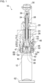
- the Figure 1 shows a device 10 for filling cans 12, and the Figure 2 shows a portion of the device 10.
- a seal 48 of the device 10 is shown as an example in a relaxed state.
- the seal 48 of the device 10 is shown by way of example in a loaded state.
- the device 10 can preferably fill the can 12 with a liquid or pasty filling material.
- the filling material can preferably be carbonated.
- the device 10 can preferably fill the can 12 using a so-called constant pressure filling method.
- a (can) filler can preferably have several of the devices 10 for filling several cans 12 at an overlapping time.
- the devices 10 can, for example, be arranged distributed around a circumference of the filler.
- the filler can preferably be designed as a rotary filler or a filler carousel. It is also possible for the filler to be a linear filler with several devices 10 arranged in one or more rows. In a can processing plant, the filler can be arranged (can-) upstream of a closing device for closing the cans.
- the device 10 has a filling valve 14, a gas channel 46 and the seal 48.
- the device 10 can, for example, also have a (further) gas channel 34, a (different) gas channel 40 and/or a can support 62.
- the filling valve 14 can fill the can 12 positioned under the filling valve 14 with the preferably carbonated filling material.
- the filling valve 14 can have a movable valve member 16 for opening and closing the filling valve 14.
- the valve member 16 can be movable along a central axis M of the filling valve 14.
- the central axis M can be a central longitudinal axis or vertical axis of the filling valve 14.
- the valve member 16 can be movable relative to a valve seat 18 of the filling valve 14.
- the valve seat 18 can preferably be a valve cone seat.
- valve member 16 In an open position, the valve member 16 can release a fluid connection between a filling material supply line 20 and a filling material outlet 22 of the filling valve 14.
- the filling material supply line 20 can be connected to the filling valve 14.
- the filling material can flow from the filling material supply line 20 to an annular gap between the valve member 16 and the valve seat 18 and from there to the filling material outlet 22.
- the filling material outlet 22 can be designed, for example, as an annular gap which is delimited on the inner circumference by the valve member 16.
- the filling material outlet 22 can be arranged coaxially to the central axis M.
- the valve member 16 can widen in a funnel shape in the region of the filling material outlet 22 towards a free end of the valve member 16.
- the filling material can flow through a filling material chamber 24 of the filling valve 14 on the way from the filling material supply line 20 to the valve seat 18.
- the valve member 16 can extend through the filling material chamber 24.
- the valve member 16 can be sealed with respect to the filling material chamber 24 with a bellows 26.
- valve member 16 In a closed position, the valve member 16 can block the fluid connection between the filling material supply line 20 and the filling material outlet 22 of the filling valve 14.
- the filling material from the filling material supply line 20 cannot pass through the valve member 16, which is in sealing contact with the valve seat 18. There is no annular gap between the valve member 16 and the valve seat 18 through which the filling material can pass.
- the valve member 16 can be prestressed in a direction along the central axis M by means of an elastic element 28 of the filling valve 14.
- the elastic element 28 can prestress the valve member 16 to lift off the valve seat 16 to open the filling valve 14.
- the valve member 16 can be prestressed in an upward direction along the central axis M by the elastic element 28.
- the elastic element 28 can be, for example, a spring, preferably a helical compression spring.
- the valve member 16 can be moved in a direction along the central axis M by means of an actuator 30 of the filling valve 14.
- the actuator 30 can move the valve member 16 preferably against a preload direction caused by the elastic element 28.
- the actuator 30 can move the valve member 16 to lower it onto the valve seat 16 to close the filling valve 14.
- the actuator 30 can move the valve member 16 along the central axis M in a downward direction.
- the actuator 30 can be a pneumatic actuator.
- the actuator 30 can be an electromagnetic actuator, for example.
- the valve member 16 can have an annular seal 32 for sealing to the valve seat 18.
- the annular seal 32 can be arranged on a conical section of the valve member 16.
- the valve seat 18 can preferably be funnel-shaped.
- the valve seat 18 can be connected, preferably integrally, to a housing part 19 of the device 10.
- the housing part 19 can, for example, be sleeve-shaped.
- the valve member 16 can be movable within the housing part 19.
- the gas channel 34 can extend parallel to the central axis M. Preferably, the gas channel 34 can extend through the valve member 16.
- a gas inlet 36 of the gas channel 34 can be arranged at an upper end region of the valve member 16.
- a gas outlet 38 of the gas channel 34 can be arranged at a lower end region of the valve member 16.
- the filling material outlet 22 can extend in a ring around the gas outlet 38.
- a compressed gas e.g. a purge gas and/or a pre-pressurizing gas, can be supplied to the can 12 via the gas channel 34.
- the gas inlet 36 can, for example, be in fluid communication with a purge valve and/or a preload valve (both not shown in the figures).
- the gas channel 40 can extend parallel to the central axis M.
- the gas channel 40 can extend as an annular channel, e.g. between two, preferably sleeve-shaped, housing parts 19 and 41 of the device 10.
- a gas inlet 42 of the gas channel 40 can be arranged at a lower end of the gas channel 40.
- the gas inlet 42 can extend in a ring around the filling material outlet 22.
- the gas channel 40 can open into a gas channel 44 at its upper end.
- the gas channel 44 is in Figure 1 only shown schematically, since it is in the cross-sectional plane of Figure 1 is not cut. Gas can escape or be discharged from the can 12 via the gas channel 40, e.g. purge gas and/or pre-pressurization gas and/or residual gas. Accordingly, the gas channel 40, 44 can be in fluid communication with a discharge line and/or a discharge valve (neither of which are shown in the figures).
- the gas channel 46 can carry a compressed gas, e.g. compressed air.
- the gas channel 46 can supply the compressed gas to the seal 48.
- the gas channel 46 can preferably extend parallel to the central axis M.
- the gas channel 46 can preferably extend through at least one, preferably sleeve-shaped, housing part 41 and/or 47 of the device 10.
- the gas channel 46 can be connected to a compressed gas source (not shown in the figures).
- the gas channel 46 can be selectively connectable to the compressed gas source in order to selectively supply or not supply the gas channel 46 with the compressed gas.
- the gas channel 46 may discharge compressed gas from the seal 48, e.g. if the gas channel 46 is (selectively) separated from the compressed gas source and/or selectively connected to a discharge line or the environment.
- the seal 48 can receive the compressed gas from the gas channel 46.
- the seal 48 can be acted upon by the compressed gas from the gas channel 46.
- the seal 48 can be elastically deformed by the received and compressed gas in a (vertical) downward direction for pressing against a circumferential upper edge 50 of the can 12 positioned under the filling valve 14 (see also Figure 2 ).
- the seal 48 can be elastically deformed by the compressed gas by at least 3 mm, at least 4 mm or at least 5 mm in the downward direction for pressing against the upper edge 50.
- the downward direction is parallel to the central axis M.
- the circumferential upper edge 50 can delimit an upper opening of the can 12.
- the circumferential upper edge 50 can be ring-shaped.
- the circumferential upper edge 50 can be, for example, a flanged edge of the can 12.
- the seal 48 can assume a relaxed state when it is not subjected to compressed gas from the gas channel 46 (see Figure 1 ).
- the seal 48 can assume a loaded state when it is loaded with compressed gas from the gas channel 46 (see Figure 2 ). In the loaded state, the seal 48 can deform elastically in the downward direction.
- the can 12 can be filled with the filling material by means of the filling valve 14.
- the can 12 can preferably be rinsed and/or pre-tensioned before filling, while the seal 48 is subjected to the compressed gas and is elastically deformed in a downward direction and pressed against the upper edge 50.
- the can 12 can be rinsed and/or pre-tensioned, for example, by means of the gas channel 34.
- the seal 48 can preferably be relaxed. When relaxed, the seal 48 can contract again. The filled can 12 can be transported further.
- the seal 48 can again be subjected to the compressed gas and can deform elastically in the downward direction and press against the upper edge 50 of the new can 12 so that it can also be flushed, pre-tensioned and/or filled.
- the seal 48 may be inflatable and/or elastically expandable in the downward direction by the compressed gas from the gas channel 46.
- the seal 48 may have an inner chamber 52 and/or a bellows portion 54 and/or a substantially U-shaped cross section.
- the inner chamber 52 is preferably annular.
- the inner chamber 52 can extend coaxially to the valve member 16 with respect to the central axis M.
- the gas channel 46 can open into the inner chamber 52.
- the inner chamber 52 can be surrounded by the bellows section 54.
- the inner chamber 52 can be arranged between the three legs of the U-shaped cross section.
- the bellows portion 54 is preferably annular.
- the bellows portion 54 may extend coaxially to the valve member 16 with respect to the central axis M.
- the bellows portion 54 may provide the elastic deformability of the seal 48.
- the bellows portion 54 may have a fold, such as in Figure 1 It is also possible for the bellows section 54 to have a plurality of folds.
- the bellows section 54 can form the two vertical legs of the U-shaped cross section of the seal 48.
- the seal 48 can be elastically deformable, for example, by a differently shaped, elastically deformable section and/or by a material elasticity of a material of the seal 48.
- the seal 48 can be secured to a preferably sleeve-shaped housing part 47 of the device 10, preferably in a force-fitting and/or form-fitting manner.
- the seal 48 can be secured to the housing part 47 of the device 10 via its two ends of its U-shaped cross section.
- the two ends can be secured, for example, in two annular grooves in the housing part 47 that are aligned opposite to one another.
- the two annular grooves can preferably extend in a plane perpendicular to the central axis M.
- the seal 48 can be thickened at the two ends.
- the seal 48 can have an annular contact surface 56.
- the contact surface 56 can be arranged on an underside of the seal 48.
- the contact surface 56 can move in the downward direction to press against the circumferential upper edge 50 when the seal 48 is elastically deformed.
- the seal 48 can center the can 12 when it is elastically deformed by the compressed gas.
- the annular contact surface 56 can be inclined to a horizontal plane. The inclination can preferably be such that the contact surface 56 rises from a circumferential inner edge of the contact surface 56 towards a circumferential outer edge of the contact surface 56 (or in a radial direction away from the central axis M), preferably in a funnel shape.
- the seal 48 can be accommodated in a seal receptacle 58 of the device 10.
- the seal receptacle 58 is preferably ring-shaped.
- the seal receptacle 58 can extend coaxially around the central axis M.
- the seal receptacle 58 can be formed by at least one, preferably sleeve-shaped, housing part 41, 60 of the device 10.
- the seal receptacle 58 is preferably only open in the downward direction.
- the seal receptacle 58 can be formed on an inner circumferential side of the seal 48 by a preferably sleeve-shaped housing part 41.
- the housing part 41 can guide the seal 48 from the inside during elastic expansion in the downward direction.
- the housing part 41 can block or at least limit elastic expansion of the seal 48 in a radial direction towards the central axis M.
- the seal receptacle 58 can be formed on an outer peripheral side of the seal 48 by a preferably sleeve-shaped housing part 60.
- the housing part 60 can guide the seal 48 from the outside during elastic expansion in the downward direction.
- the housing part 60 can block or at least limit elastic expansion of the seal 48 in a radial direction away from the central axis M.
- the housing part 60 can be attached to the housing part 41, e.g. by means of a screw connection.
- the seal receptacle on a rear side of the seal 48 can be formed by a preferably sleeve-shaped housing part 47.
- the housing part 47 can, for example, be arranged between the housing parts 19 and 60.
- the seal 48 In the relaxed state of the seal 48, the seal 48 may be positioned entirely within the seal receptacle 58.
- the contact surface 56 of the seal 48 may be substantially flush with or recessed from a lower opening of the seal receptacle 58.
- the seal 48 When the seal 48 is in the loaded state, the seal 48 can protrude from the seal receptacle 58 in a downward direction. For example, the contact surface 56 of the seal 48 can protrude beyond the lower opening of the seal receptacle 58 when the seal 48 is in the loaded state.
- the can support 62 can support the can 12.
- the can support 62 can, for example, have a support plate that supports the can 12 on the bottom.
- the can support 62 can, for example, have a can holder that supports the can 12 on a lateral surface of the can 12 (not shown in the figures).
- the can holder can, for example, be designed as a clamp, gripper or pocket.
- the device 10 can be free of a lifting device for vertically moving the filling valve 14 and free of a lifting device for vertically moving the can support 62. Accordingly, neither the can 12 nor the filling valve 14 can have a lifting movement relative to each other. to bring the filling valve 14 and the can 12 closer together before filling. Instead, the elastic deformation of the seal 48 can overcome the inlet gap between the filling valve 14 and the upper edge 50 of the can 12 and seal during filling.
- the Figure 3 shows a section of a Figures 1 and 2 modified embodiment.
- the bellows section 54' of the seal 48 has a plurality of folds. The folds are arranged one above the other and connected to one another.
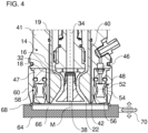
- the Figure 4 shows an optional addition for the device 10.
- the device 10 can have a cleaning cap 64.
- the cleaning cap 64 is preferably designed as a so-called CIP cleaning cap or cleaning-in-place cleaning cap.
- the cleaning cap 64 is preferably bowl-shaped.
- the cleaning cap 64 can, for example, have a chamber 66.
- the chamber 66 can be open at the top or have an opening at the top.
- the chamber 66 can, for example, have a tub-shaped, pot-shaped or omega-shaped cross-section.
- the chamber 66 can be dimensioned and arranged such that the seal 48 can be elastically deformed downwards into the chamber 66 when subjected to the compressed gas.
- the chamber 66 can have a diameter that is greater than or equal to an outer diameter of the seal 48 and/or the seal receptacle 58.
- An annular sealing element 68 may be arranged on a top of the cleaning cap 64.
- the sealing element 68 may surround the top opening of the chamber 66.
- a diameter of the sealing element 68 essentially corresponds to a diameter of a bottom side of the housing part 60.
- the sealing element 68 can seal between the cleaning cap 64 and the housing part 60 when it sealingly contacts the housing part 60 from below (see Figure 4 ).
- the diameter of the sealing element 68 can, for example, essentially correspond to an outer diameter of the housing part 60.
- the sealing element 68 can seal between the cleaning cap 64 and the housing part 60 when it sealingly contacts the housing part 60 at its outer circumference (not shown in Figure 4 ).
- the cleaning cap 64 can be moved by means of a purely schematically illustrated positioning device 70.
- the cleaning cap 64 can perform a lifting movement, a horizontal pivoting movement and/or a horizontal sliding movement by means of the positioning device 70.
- the cleaning cap 64 is arranged in a sealed manner under the filling valve 14 and the seal 48, the actual cleaning of the filling valve 14 and the seal 48 can take place.
- a cleaning fluid can be supplied to the filling valve 14, which flows through the filling valve 14 and chamber 66 and in the process cleans the filling valve 14 and the seal 48.
- the seal 48 can be exposed to the compressed gas during cleaning.
- the seal 48 can then elastically deform downwards into the chamber 66 of the cleaning cap 64 and, for example, enable improved flushing of the seal 48.
- the compressed gas can, for example, only be exposed to it temporarily during cleaning and/or several times in succession during cleaning.
- the invention is not limited to the preferred embodiments described above. Rather, a large number of variants and modifications are possible, which also make use of the inventive concept and therefore fall within the scope of protection.
- the invention also claims protection for the subject matter and the features of the subclaims independently of the claims referred to.
- the individual features of independent claim 1 are each disclosed independently of one another.
- the features of the subclaims are also disclosed independently of all features of independent claim 1 and, for example, independently of the features relating to the presence and/or configuration of the filling valve, the gas channel and/or the seal of independent claim 1. All area specifications herein are to be understood as disclosed in such a way that all values falling within the respective area are disclosed individually, e.g. also as preferred narrower outer boundaries of the respective area.
Landscapes
- Filling Of Jars Or Cans And Processes For Cleaning And Sealing Jars (AREA)
Applications Claiming Priority (1)
| Application Number | Priority Date | Filing Date | Title |
|---|---|---|---|
| DE102023105234.9A DE102023105234A1 (de) | 2023-03-03 | 2023-03-03 | Vorrichtung zum Füllen von Dosen und Verfahren zum Betreiben der Vorrichtung |
Publications (1)
| Publication Number | Publication Date |
|---|---|
| EP4431445A1 true EP4431445A1 (fr) | 2024-09-18 |
Family
ID=90059353
Family Applications (1)
| Application Number | Title | Priority Date | Filing Date |
|---|---|---|---|
| EP24159591.7A Pending EP4431445A1 (fr) | 2023-03-03 | 2024-02-26 | Dispositif de remplissage de canettes et procédé d'operation du dispositif |
Country Status (4)
| Country | Link |
|---|---|
| US (1) | US12522493B2 (fr) |
| EP (1) | EP4431445A1 (fr) |
| CN (1) | CN117865046A (fr) |
| DE (1) | DE102023105234A1 (fr) |
Cited By (1)
| Publication number | Priority date | Publication date | Assignee | Title |
|---|---|---|---|---|
| EP4714896A1 (fr) * | 2024-09-23 | 2026-03-25 | Pivo To Go, s.r.o. | Appareil de remplissage pour le remplissage d'un récipient avec du liquide carbonaté |
Citations (5)
| Publication number | Priority date | Publication date | Assignee | Title |
|---|---|---|---|---|
| US3519035A (en) | 1967-03-23 | 1970-07-07 | Applic Gaz Sa | Volumetric dosing device |
| US5156200A (en) | 1989-08-11 | 1992-10-20 | Alfill Getranketechik GmbH | Apparatus for filling bottles and the like |
| US5196200A (en) | 1991-04-25 | 1993-03-23 | International Flavors & Fragrances Inc. | Bisabolene-containing composition, process for preparing same, organoleptic uses thereof and uses thereof as insect repellent |
| WO2014139641A1 (fr) * | 2013-03-13 | 2014-09-18 | Khs Gmbh | Procédé et machine de remplissage pour remplir des canettes ou des contenants similaires avec un produit de remplissage liquide |
| DE102016124216B3 (de) * | 2016-12-13 | 2018-05-09 | Khs Gmbh | Füllelementanordnung sowie Füllmaschine |
Family Cites Families (6)
| Publication number | Priority date | Publication date | Assignee | Title |
|---|---|---|---|---|
| DE3931834A1 (de) * | 1989-09-23 | 1991-04-04 | Seitz Enzinger Noll Masch | Fuellorgan fuer fuellmaschinen zum fuellen von dosen oder dergleichen behaelter |
| US20100037983A1 (en) * | 2008-08-12 | 2010-02-18 | The Coca-Cola Company | Neck ring seal |
| US9156669B2 (en) * | 2009-06-26 | 2015-10-13 | Sidel S.P.A. | Liquid bottling method and machine, in particular for carbonated liquids or oxygen sensitive liquids |
| CN103112813A (zh) * | 2013-01-25 | 2013-05-22 | 南京保立隆包装机械有限公司 | 一种含果粒易拉罐饮料的灌装阀 |
| DE102013113070B3 (de) * | 2013-11-26 | 2015-03-19 | Khs Gmbh | Füllelement sowie Füllmaschine |
| CN111137825B (zh) * | 2020-02-28 | 2024-09-20 | 江苏辉河包装机械有限公司 | 一种灌装阀 |
-
2023
- 2023-03-03 DE DE102023105234.9A patent/DE102023105234A1/de active Pending
-
2024
- 2024-02-26 EP EP24159591.7A patent/EP4431445A1/fr active Pending
- 2024-03-01 CN CN202410236682.XA patent/CN117865046A/zh active Pending
- 2024-03-03 US US18/593,917 patent/US12522493B2/en active Active
Patent Citations (5)
| Publication number | Priority date | Publication date | Assignee | Title |
|---|---|---|---|---|
| US3519035A (en) | 1967-03-23 | 1970-07-07 | Applic Gaz Sa | Volumetric dosing device |
| US5156200A (en) | 1989-08-11 | 1992-10-20 | Alfill Getranketechik GmbH | Apparatus for filling bottles and the like |
| US5196200A (en) | 1991-04-25 | 1993-03-23 | International Flavors & Fragrances Inc. | Bisabolene-containing composition, process for preparing same, organoleptic uses thereof and uses thereof as insect repellent |
| WO2014139641A1 (fr) * | 2013-03-13 | 2014-09-18 | Khs Gmbh | Procédé et machine de remplissage pour remplir des canettes ou des contenants similaires avec un produit de remplissage liquide |
| DE102016124216B3 (de) * | 2016-12-13 | 2018-05-09 | Khs Gmbh | Füllelementanordnung sowie Füllmaschine |
Non-Patent Citations (1)
| Title |
|---|
| JULIAN H DRIVER ET AL: "Design of Aluminum Rolling Processes for Foil, Sheet, and Plate", 1 January 2004 (2004-01-01), XP009552727, ISBN: 978-0-8247-4106-8, Retrieved from the Internet <URL:https://www.routledgehandbooks.com/doi/10.1201/9781351045636-140000401> [retrieved on 20190101] * |
Cited By (1)
| Publication number | Priority date | Publication date | Assignee | Title |
|---|---|---|---|---|
| EP4714896A1 (fr) * | 2024-09-23 | 2026-03-25 | Pivo To Go, s.r.o. | Appareil de remplissage pour le remplissage d'un récipient avec du liquide carbonaté |
Also Published As
| Publication number | Publication date |
|---|---|
| DE102023105234A1 (de) | 2024-09-05 |
| CN117865046A (zh) | 2024-04-12 |
| US20240294369A1 (en) | 2024-09-05 |
| US12522493B2 (en) | 2026-01-13 |
Similar Documents
| Publication | Publication Date | Title |
|---|---|---|
| EP0412480B1 (fr) | Dispositif de remplissage de récipients | |
| EP2598429B1 (fr) | Machine de remplissage | |
| EP2788275B1 (fr) | Élément de remplissage pourvu d'un tube trinox | |
| EP2969894B1 (fr) | Procédé et machine de remplissage pour remplir des canettes ou des contenants similaires avec un produit de remplissage liquide | |
| EP0290726B1 (fr) | Mécanisme de remplissage de gobelets destinés à des produits nutritifs et d'agrément, en particulier à des produits laitiers | |
| EP2010447A1 (fr) | Élément de remplissage et machine de remplissage avec élément de remplissage | |
| EP2117986B1 (fr) | Procédé de bouchage de récipients et machine à boucher | |
| EP1692071A1 (fr) | Element de remplissage pour machine de remplissage et machine de remplissage equipee d'elements de remplissage de ce type | |
| EP2307306B1 (fr) | Système de remplissage pour remplir des bouteilles ou récipients similaires et machine de remplissage correspondante | |
| EP2751016B1 (fr) | Élément de levage doté d'une douille de rinçage rétractable | |
| DE69403633T2 (de) | Einrichtung zum entladen von schuttfähigem stoff | |
| DE3809852A1 (de) | Verfahren zum aseptischen bzw. sterilen abfuellen von fluessigem fuellgut in behaelter sowie vorrichtung zum durchfuehren dieses verfahrens | |
| EP3105169B1 (fr) | Procédé et système de remplissage de récipients | |
| EP3356285B1 (fr) | Procédé et station de traitement de fûts | |
| DE102014102953A1 (de) | Vorrichtung und Verfahren zum Befüllen eines Behälters mit einem Füllprodukt | |
| EP4431445A1 (fr) | Dispositif de remplissage de canettes et procédé d'operation du dispositif | |
| EP2768762B1 (fr) | Procédé et machine de remplissage de bouteilles avec un produit à conditionner liquide | |
| EP3693333B1 (fr) | Dispositif de traitement d'un récipient | |
| WO2019002466A2 (fr) | Dispositif de traitement d'un récipient dans un système remplissage par un produit de remplissage | |
| WO2020074316A1 (fr) | Dispositif pour remplir et fermer des récipients | |
| EP1544157B1 (fr) | Machine de remplissage pour remplir des récipients | |
| EP3554987B1 (fr) | Ensemble élément de remplissage et machine de remplissage | |
| EP2813462A1 (fr) | Dispositif et procédé de remplissage d'un récipient avec un produit de remplissage | |
| CH695611A5 (de) | Entleereinrichtung für einen Schüttgut-Container. | |
| EP0499776A1 (fr) | Tête de remplissage destinée à remplir un récipient de liquide |
Legal Events
| Date | Code | Title | Description |
|---|---|---|---|
| PUAI | Public reference made under article 153(3) epc to a published international application that has entered the european phase |
Free format text: ORIGINAL CODE: 0009012 |
|
| STAA | Information on the status of an ep patent application or granted ep patent |
Free format text: STATUS: THE APPLICATION HAS BEEN PUBLISHED |
|
| AK | Designated contracting states |
Kind code of ref document: A1 Designated state(s): AL AT BE BG CH CY CZ DE DK EE ES FI FR GB GR HR HU IE IS IT LI LT LU LV MC ME MK MT NL NO PL PT RO RS SE SI SK SM TR |
|
| STAA | Information on the status of an ep patent application or granted ep patent |
Free format text: STATUS: REQUEST FOR EXAMINATION WAS MADE |
|
| 17P | Request for examination filed |
Effective date: 20250317 |