EP4431477A1 - Système de montage pour la fabrication d'un composite stratifié et procédé de fabrication d'un composite stratifié - Google Patents
Système de montage pour la fabrication d'un composite stratifié et procédé de fabrication d'un composite stratifié Download PDFInfo
- Publication number
- EP4431477A1 EP4431477A1 EP23161565.9A EP23161565A EP4431477A1 EP 4431477 A1 EP4431477 A1 EP 4431477A1 EP 23161565 A EP23161565 A EP 23161565A EP 4431477 A1 EP4431477 A1 EP 4431477A1
- Authority
- EP
- European Patent Office
- Prior art keywords
- layer
- seal
- adhesive
- assembly system
- internal volume
- Prior art date
- Legal status (The legal status is an assumption and is not a legal conclusion. Google has not performed a legal analysis and makes no representation as to the accuracy of the status listed.)
- Withdrawn
Links
Images



Classifications
-
- C—CHEMISTRY; METALLURGY
- C03—GLASS; MINERAL OR SLAG WOOL
- C03C—CHEMICAL COMPOSITION OF GLASSES, GLAZES OR VITREOUS ENAMELS; SURFACE TREATMENT OF GLASS; SURFACE TREATMENT OF FIBRES OR FILAMENTS MADE FROM GLASS, MINERALS OR SLAGS; JOINING GLASS TO GLASS OR OTHER MATERIALS
- C03C27/00—Joining pieces of glass to pieces of other inorganic material; Joining glass to glass other than by fusing
- C03C27/06—Joining glass to glass by processes other than fusing
- C03C27/10—Joining glass to glass by processes other than fusing with the aid of adhesive specially adapted for that purpose
Definitions
- the present invention relates to an assembly system for producing a layered composite, comprising: a layer arrangement comprising a first layer, a second layer opposite the first layer and a first seal laterally contacting the first layer and the second layer, so that the first layer, the second layer and the first seal define an intermediate and closed or closable first internal volume that can be filled with a fluid.
- the assembly system also includes a fixing element that laterally contacts the first seal on its side opposite the layer arrangement.
- the invention further relates to a method for producing a layered composite using an assembly system according to the invention, wherein in the assembly system at least a part of the first seal exerts a pressure against the side of the layer arrangement contacted thereby.
- Laminated glass consists of at least two glass panels and an intermediate layer that connects the glass panels together.
- the glass panels can be selected in any combination from inorganic glasses such as float glass, white glass, toughened safety glass, partially tempered glass, colored glass, coated glass, mirrored glass, thin-film solar modules, and from organic glasses such as polycarbonate (PC) or polymethyl methacrylate glass (PMMA).
- inorganic glasses such as float glass, white glass, toughened safety glass, partially tempered glass, colored glass, coated glass, mirrored glass, thin-film solar modules
- organic glasses such as polycarbonate (PC) or polymethyl methacrylate glass (PMMA).
- Laminated glass is used, for example, as laminated glass with safety and/or soundproofing properties, in the protection of surfaces by bonding them to a pane of glass or in the production of solar modules.
- a widely used method for producing laminated glass with a hardenable intermediate layer is to fill a pane package consisting of two cleaned glass panels placed at a certain distance from each other with a low-viscosity casting resin.
- the cavity between the two glass panels is sealed to the outside with, for example, a double-sided adhesive tape placed between the two glass panels.
- This edge sealing can also be made with a butyl cord containing a hard core made of a thermoplastic polymer such as polypropylene.
- the cast resin layer between the glass panels hardens.
- a thermoplastic material for example with a hot melt adhesive or with a butyl cord
- hardening can be achieved by UV light or thermally. and in the case of a multi-component system, by storage at room temperature or by application of heat.
- WO 2000/09328 A1 describes such a process for producing laminated glass, whereby an adhesive with a viscosity of 5 to 300 Pa*s (23 °C) and a yield point of 5 to 800 Pa (23 °C) is applied to the inside of a first, horizontally lying glass panel, a second glass panel is placed congruently on this adhesive layer to form a sandwich arrangement, these are pressed together and the adhesive is then allowed to harden.
- WO 2015/097111 A1 describes a method for producing a layered composite, wherein the layered composite comprises a substrate, a cover layer and an adhesive layer arranged between the substrate and the cover layer.
- the adhesive layer contacts the substrate and the cover layer at least partially.
- the method comprises the step of pivoting the substrate and the cover layer towards one another so that the distance between the upper substrate edge and the upper cover layer edge decreases and the adhesive is moved in the direction of the upper substrate edge and the upper cover layer edge. This is carried out in such a way that during at least part of step B) the bisector (1000) of the angle ⁇ forms an angle of ⁇ -45° to ⁇ 45° with respect to the vertical.
- the utility model DE 202013105933 U1 discloses a layered composite comprising a substrate, a cover layer and a cured adhesive layer arranged between the substrate and the cover layer, wherein the adhesive layer at least partially contacts the substrate and the cover layer.
- the substrate comprises a mineral material
- the cover layer comprises a glass
- an electrical functional unit is arranged between the substrate and the cover layer and in the layered composite the average content of gas bubbles enclosed in the adhesive layer with a maximum extension of ⁇ 100 ⁇ m is less than 100 gas bubbles/m 2 .
- the present invention has set itself the task of improving the production of laminated glass and other layer composites in such a way that a bubble-free or at least bubble-poor bonding of the layers can be achieved in a space-time efficient, automatable and highly scalable manufacturing process.
- this object is achieved by a mounting system according to claim 1 and a method according to claim 10.
- the assembly system and method according to the invention make it possible to only carry out the pre-assembly of the layers to be bonded under clean room conditions. As soon as the seal in the assembly system isolates the internal volume and thus also the layers to be bonded from the outside environment, the assembly system can also be processed outside of a clean room. A large number of parts can be prepared in parallel and further processed with optimal time utilization of a press and a possible UV exposure unit for curing the adhesive.
- FIG.1 shows a schematic exploded drawing of an assembly system according to the invention for producing a layered composite, comprising a layer arrangement comprising a first layer 100, a second layer 200 opposite the first layer 100 and a first seal 300 laterally contacting the first layer 100 and the second layer 200, so that an intermediate and closed or lockable first internal volume 400 that can be filled with a fluid is defined by the first layer 100, the second layer 200 and the first seal 300.
- the first layer 100 and the second layer 200 can be connected to one another by means of an adhesive filled into the first internal volume.
- the assembly system according to the invention fixes the layers 100, 200 to be bonded, with the internal volume 400 being kept ready for filling in the adhesive.
- the inner volume 400 is also sealed by the first seal 300.
- the first seal 300 can be made in one piece or in multiple pieces, with the one-piece variant contacting the layers 100, 200 all the way around being preferred. It is also preferred that the first seal 300 is removable from the assembly system. In this way, seals dimensioned for the specific application can be used and dirty or worn seals can be easily replaced.
- the material of the first seal 300 contains a silicone polymer. It is also possible to provide the surface of a non-silicone material with a silicone polymer and use it as the first seal 300, as long as this surface faces the direction of the internal volume.
- the seals can be manufactured in a very simple way.
- the shape of the seal can be made in a pre-milled 2D sealing form (CNC-milled wooden board) for every application that needs to be sealed.
- the edge to the frame 500 can be straight.
- the edge to the layer arrangement can be straight, concave, convex, acute-angled, jagged, stepped or in the shape to be produced.
- the seal can have a corresponding bead (a profile) that can be mechanically tensioned/pulled on so that it remains fixed to the frame 500 when the frame 500 is pulled on (first seal 300 retracted).
- the first seal 300 can then be secured via this bead so that it does not slip out when pulled on.
- the layers to be bonded can have 100, 200, different sizes or shapes, so that a step, a fold or even a groove can be created by means of bonding.
- the frame 500 can also be designed in such a way that it is scalable in the desired material package thickness to be produced.
- the frame 500 can be designed in one piece or in multiple pieces.
- it can have two units: a front and a rear frame unit with a vacuum on both sides, specifically a fine, flat vacuum on the inside, in order to be able to hold a polymer film pre-tensioned between the first layer 100 and the second layer 200 and beyond the dimensions of the layer arrangement in shape until the curing of the adhesive is complete.
- the frame 500 can be used as a template to specify the shape of the layered composite or to support its shaping. Taking this into account, the frame 500 can be flat over its entire surface, but also have a flat shape worked on a slope.
- the frame 500 is basically not restricted in its design, it can also be angled, curved, arched, whether concave or convex, in its own shape.
- the frame 500 can be designed in any conceivable size, including for processing XXL glass surfaces (20 x 3.3 meters) and for small formats (business cards).
- the frame 500 can be made of metal or plastic.
- the frame 500 is preferably reusable.
- the assembly system according to the invention can also contain more layers, for example a third layer, and also more seals, for example a second seal.
- the material of the first seal 300 has a maximum elongation, determined in the tensile test according to ISO 527-1/-2, of ⁇ 50% and more preferably ⁇ 100%. It is further preferred that the material of the first seal 300 has a resilience at 50% elongation, determined in the tensile test according to ASTM D412, of ⁇ 90%.
- the assembly system further comprises at least one fixing element which laterally contacts the first seal 300 on its side opposite the layer arrangement.
- This is in FIG.1 not shown in detail, but can be integrated, for example, within the frame 500.
- Some of the fixing elements can also be formed by the frame 500 itself.
- At least one fixing element is designed to be moved against the first seal 300, so that the first seal 300 exerts a pressure on the layer arrangement.
- the first seal 300 is designed to exert a pressure on the layer arrangement by filling it with a fluid (for example, inflating it using compressed air). This is also described in FIG.1 not shown in detail.
- This movable fixing element can, in the retracted state, enable the layers 100, 200 (for example glass panes) to be inserted into the assembly system and, in the extended state, press the first seal 300 against the layers 100, 200.
- a plurality of fixing elements can also be set up to be moved against the side of the first seal 300 that is in contact with them.
- at least half of the fixing elements are set up to be movable in this way and particularly preferably all of the fixing elements are set up to be movable in this way.
- the layers 100, 200 can be brought into a spatial position that is favorable for their pressing with adhesive, for example, standing vertically.
- the first seal is accessible at at least one position so that a fluidic connection can be created through the first seal into the inner volume. This is also in FIG.1 not shown in detail. Access can be achieved through a recess in the frame 500.
- the fluidic connection can be achieved, for example, through a recess in the frame 500 in conjunction with piercing the first seal 300 or with a hose line leading through the first seal 300 and a recess in the frame 500.
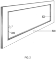
- FIG.2 The mobility of the first seal 300 for inserting and fixing layer arrangements provided in the assembly system is determined in FIG.2 and FIG.3 shown schematically.
- FIG.2 the first seal 300 is in a retracted state, thereby providing enough space for the insertion of the layer arrangement into the frame 500.
- FIG.3 the first seal 300 is now in the extended state, whereby a layer arrangement can be fixed in the frame 500 by the pressure exerted on the layer arrangement by the first seal.
- FIG.4 shows a transport arrangement in which, in an assembly system according to the invention, the first layer 100 and second layer 200 are fixed in the frame 500 by the extended first seal 300.
- Chain hoists 600 are attached to the top of the frame 500, which enable the assembly system to be transported by means of overhead cranes or the like.
- the first layer 100 and the second layer 200 are not arranged parallel to each other. This is in contrast to the FIG.1 shown arrangement, in which the layers 100, 200 are arranged essentially parallel to one another.
- the non-parallel arrangement can ensure that when the layers 100, 200 are pressed together, the adhesive between them is pressed in a certain direction, whereby any gas bubbles trapped in the adhesive are also directed in a controlled direction. This can be used for bubble-free bonding of the layers 100, 200 if the direction is selected appropriately, in particular upwards (against the direction of gravity).
- the first layer 100 and the second layer 200 can, for example, be arranged such that they form a "V" in cross section with an opening pointing upwards.
- the material of layers 100 and 200 can be the same or different.
- suitable materials are mineral materials or glass.
- Suitable mineral materials are, for example, stone, natural stone, concrete, gypsum and the like.
- Natural stone is generally understood to mean all rocks as they are found in nature.
- Preferred natural stones are granite, marble, quartz, Quartz composite, travertine, sandstone, slate and agate.
- the thickness of layers 100 and/or 200 is independently ⁇ 1 mm to ⁇ 40 mm and more preferably ⁇ 2 mm to ⁇ 20 mm.
- the first and/or the second layer are 100, 200 layers of glass.
- the glass can be colored or uncolored.
- suitable glasses are E-glass, S-glass, M-glass, quartz glass, borosilicate glass, crown glass, soda-lime glass, float glass, flint glass and/or lead crystal glass.
- the first seal 300 is at least partially transparent.
- it can be transparent to light that is used to cure a UV-curing adhesive.
- An example of a suitable wavelength is 254 nm.
- the material of the first seal 300 contains a silicone polymer with a surface tension of ⁇ 20 mN/m to ⁇ 30 mN/m.
- the surface tension can be determined according to DIN ISO 8296, in particular using test inks taking this standard into account.
- the surface tension is preferably ⁇ 22 mN/m to ⁇ 26 mN/m.
- Such surface tensions prevent interaction of the seal with the adhesive, in particular a UV-curing adhesive, which can additionally contain optional reactive thinners. Undesirable interactions can result in leaks in the first seal 300.
- a further production-related advantage of preventing interactions between the adhesive and the first seal 300 is that the seal is then not a disposable item, but can be used multiple times.
- an adhesive is present in the first internal volume 400.
- the adhesive is preferably transparent and in particular a two-component adhesive such as epoxy, (meth)acrylate and polyurethane resins or a radiation-curing adhesive such as (meth)acrylates and urethane (meth)acrylates. Dual cure adhesives are also suitable, in which radiation curing and curing without radiation take place alongside one another or one after the other.
- the adhesive can also contain reactive diluents such as monomeric (meth)acrylates as part of its formulation.
- the assembly system filled with the adhesive represents a further step in the process chain for producing a layered composite, as will be explained further below.
- an intermediate layer is also present between the first and the second layer 100, 200.
- suitable intermediate layers are intermediate layers comprising wood, natural stone and/or polymers.
- the intermediate layer can also have a electrical functional unit, in particular a display device, a photovoltaic device or an electrically controlled darkening device.
- the first internal volume 400 is fluidically accessible through one or more hose lines or hose lines 1000, 1100 leading through the first seal 300.
- the internal volume 400 can thus be filled with an adhesive. It is preferable to use at least two hose lines. The adhesive can then be filled through one hose line and the air displaced during filling can escape from the other hose line. In an extension of this concept, a negative pressure can also be applied to the internal volume 400 using the other hose line.
- At least one fixing element is designed to be moved hydraulically, pneumatically and/or electrically against the side of the layer arrangement contacted by it.
- Pneumatic actuators are preferred because the pressure built up after valves are closed can be maintained without the assembly system having to be connected to a hydraulic line or electrical power line.
- the frame 500 can have pressure elements for pressing with air, adapted to the shape to be produced, in the size that presses the seal from the frame construction into the middle of the frame.
- the pressure is adjustable.
- the frame 500 can be equipped with a surface vacuum on both sides.
- the assembly frame can have an acoustic signaling system that reports this to the user in the event of a loss of pressure.
- FIG.5 One possibility to provide the assembly system according to the invention according to step I) begins with the FIG.5
- the assembly system with frame 500 and retracted first seal 300 accommodates the first layer 100 and second layer 200 inserted therein.
- the frame 500 is held in place by vacuum fixing elements 700, 710, 720.
- the vacuum fixing elements 700, 710, The layer of first layer 100 and second layer 200 facing 720 is also held by these vacuum fixing elements so that frame 500 and the respective layer are flush with each other.
- at least the first seal 300 can be extended to exert pressure on the layer arrangement of the first layer 100 and the second layer 200.
- FIG.7 A further possibility to provide the assembly system according to the invention according to step I) is in FIG.7
- the frame 500 with first seal 300 and layer arrangement of first layer 100 and second layer 200 inserted therein is fixed on both sides by vacuum fixing elements 700-750.
- the first layer 100 and the second layer 200 are also held in place by the vacuum fixing elements that contact them and thus end flush with the frame 500.
- the dimensioning of the frame 500 can be used in conjunction with FIG.1 shown internal volume 400 can be built up. After extending the first seal 300, the arrangement is fixed and can be transported.
- step II) of the method it is ensured that an adhesive is present in the internal volume between the first layer 100 and the second layer 200. Details of the adhesive have already been given previously and will not be presented again to avoid repetition.
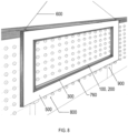
- the adhesive can be filled, for example, if the assembly system is in accordance with FIG.7 But it is also possible and in FIG.8 shown to use a surface vacuum fixing unit 800.
- the assembly system with the first seal 300 extended is transported to the fixing unit 800 via chain hoists 600 and secured there.
- the height adjusters 900 allow the assembly system with frame 500, extended first seal 300 and the layer arrangement therein with first layer 100 and second layer 200 to be placed non-horizontally.
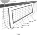
- FIG.9 Filling the adhesive is in FIG.9 shown.
- the assembly system held in the fixing unit 800 with frame 500, extended first seal 300 and layer arrangement therein with first layer 100 and second layer 200 is arranged at an angle by horizontally offset height adjusters 900, 1000.
- the adhesive 1020 can be filled from the storage container 1010 at the lowest point of the internal volume via the hose line 1000, which leads through the first seal 300.
- the hose line 1100 leads through the first seal 300 at the highest point of the internal volume and can allow gas displaced by the adhesive 1020 to escape.
- Positioning the adhesive storage container 1010 vertically above the highest point of the internal volume has the advantage that the adhesive can be easily filled by gravity and that any gas bubbles present in the adhesive can escape upwards from the storage container 1010, while the adhesive itself can flow out of the storage container 1010 at the bottom.
- the internal volume Before filling the adhesive, the internal volume can be flushed with an inert gas. It is also possible to carry out a leak test. To do this, an overpressure can be applied to the internal volume, the connection to the overpressure source can be disconnected and the presence of a pressure drop in the internal volume can be monitored. Leaking assembly arrangements, for example due to worn seals, can then be identified and sorted out before filling with adhesive.
- step III) of the method the layer arrangement is pressed in the assembly system by means of a pressing device.
- a part of the pressing device can be FIG.8 and FIG.9 shown surface vacuum fixing unit 800 can be formed.
- Another part of the pressing device can then act specifically on the layer arrangement with first layer 100 and second layer 200.
- the pressure that the first seal 300 exerts against the layer arrangement can change.
- a comparatively high pressure can serve to fix a transport configuration of the assembly system and a comparatively low pressure can promote the mobility of the first layer 100 and/or the second layer 200 during pressing.
- step III the first layer 100 and/or the second layer 200 are moved over the surface of the first seal 300.
- the curing of the filled adhesive in step IV) depends on the type of adhesive, but photochemical and thermal curing are particularly suitable. Curing can take place while the assembly is still being pressed in a press assembly or is still being stored there.
- the bonded layer arrangement can be removed and the rest of the assembly system can be returned to the production process.
- the adhesive is subjected to a negative pressure before, during and/or after filling. This way, as in FIG.9 As shown, this negative pressure is applied via the hose line 1100. In addition to accelerating the filling process, especially with higher viscosity adhesives, further degassing of the adhesive can take place.
- the assembly system is removed from the pressing device before the adhesive hardens in step IV).
- step III) is carried out in such a way that after the layer arrangement has been pressed in the assembly system, at least the first and second layers are arranged parallel to one another. This represents the desired end state for multi-layer composites, in particular laminated glass.
- the adhesive is a radiation-curing adhesive and the curing in step IV) takes place by irradiating the adhesive.
- step III the layer arrangement is pressed in an upright position.
- the bisector of the angle formed between the first layer 100 and the second layer 200 can assume an angle of +45° to -45° to the vertical.
- step I) an assembly system is provided in which the first layer 100 and the second layer 100 are not arranged parallel to one another, with the side of the layer arrangement with the greatest distance between the first layer 100 and the second layer 200 facing upwards.
- the non-parallel arrangement can ensure that when the layers 100, 200 are pressed together, the adhesive located between them is pressed in a certain direction, whereby any gas bubbles trapped in the adhesive are also directed in a controlled direction. This can be used for bubble-free bonding of the layers 100, 200 if the direction is selected appropriately, in particular upwards (against the direction of gravity).
- the first layer 100 and the second layer 200 can, for example, be arranged in such a way that they form a "V" in cross section with an opening facing upwards.
- step III) the pressing takes place at a pressure of ⁇ 1 bar to ⁇ 10 bar, preferably at a pressure of ⁇ 2 bar to ⁇ 8 bar.
- At least in step III) at least one fixing element exerts a pressure of ⁇ 1 bar to ⁇ 10 bar on the side of the layer arrangement contacted by it.
- This pressure is preferably ⁇ 2 bar to ⁇ 8 bar.
Landscapes
- Chemical & Material Sciences (AREA)
- Engineering & Computer Science (AREA)
- Ceramic Engineering (AREA)
- Life Sciences & Earth Sciences (AREA)
- Chemical Kinetics & Catalysis (AREA)
- General Chemical & Material Sciences (AREA)
- Geochemistry & Mineralogy (AREA)
- Materials Engineering (AREA)
- Organic Chemistry (AREA)
- Joining Of Glass To Other Materials (AREA)
Priority Applications (2)
| Application Number | Priority Date | Filing Date | Title |
|---|---|---|---|
| EP23161565.9A EP4431477A1 (fr) | 2023-03-13 | 2023-03-13 | Système de montage pour la fabrication d'un composite stratifié et procédé de fabrication d'un composite stratifié |
| PCT/EP2024/056534 WO2024189015A1 (fr) | 2023-03-13 | 2024-03-12 | Système d'assemblage pour la fabrication d'un composite stratifié et procédé de fabrication d'un composite stratifié |
Applications Claiming Priority (1)
| Application Number | Priority Date | Filing Date | Title |
|---|---|---|---|
| EP23161565.9A EP4431477A1 (fr) | 2023-03-13 | 2023-03-13 | Système de montage pour la fabrication d'un composite stratifié et procédé de fabrication d'un composite stratifié |
Publications (1)
| Publication Number | Publication Date |
|---|---|
| EP4431477A1 true EP4431477A1 (fr) | 2024-09-18 |
Family
ID=85601572
Family Applications (1)
| Application Number | Title | Priority Date | Filing Date |
|---|---|---|---|
| EP23161565.9A Withdrawn EP4431477A1 (fr) | 2023-03-13 | 2023-03-13 | Système de montage pour la fabrication d'un composite stratifié et procédé de fabrication d'un composite stratifié |
Country Status (2)
| Country | Link |
|---|---|
| EP (1) | EP4431477A1 (fr) |
| WO (1) | WO2024189015A1 (fr) |
Citations (4)
| Publication number | Priority date | Publication date | Assignee | Title |
|---|---|---|---|---|
| DE2555382A1 (de) * | 1974-12-12 | 1976-06-16 | Saint Gobain | Isolierscheibe mit hochwertigen akustischen eigenschaften |
| WO2000009328A1 (fr) | 1998-08-13 | 2000-02-24 | Chemetall Gmbh | Procede de production de verre feuillete |
| DE202013105933U1 (de) | 2013-12-23 | 2014-04-03 | Thomas Hofberger GmbH | Schichtenverbund mit mineralischem Werkstoff und Glas |
| DE102013114856A1 (de) * | 2013-12-23 | 2015-06-25 | Thomas Hofberger GmbH | Schichtenverbund mit mineralischem Werkstoff und Glas und Verfahren zu dessen Herstellung |
-
2023
- 2023-03-13 EP EP23161565.9A patent/EP4431477A1/fr not_active Withdrawn
-
2024
- 2024-03-12 WO PCT/EP2024/056534 patent/WO2024189015A1/fr not_active Ceased
Patent Citations (5)
| Publication number | Priority date | Publication date | Assignee | Title |
|---|---|---|---|---|
| DE2555382A1 (de) * | 1974-12-12 | 1976-06-16 | Saint Gobain | Isolierscheibe mit hochwertigen akustischen eigenschaften |
| WO2000009328A1 (fr) | 1998-08-13 | 2000-02-24 | Chemetall Gmbh | Procede de production de verre feuillete |
| DE202013105933U1 (de) | 2013-12-23 | 2014-04-03 | Thomas Hofberger GmbH | Schichtenverbund mit mineralischem Werkstoff und Glas |
| DE102013114856A1 (de) * | 2013-12-23 | 2015-06-25 | Thomas Hofberger GmbH | Schichtenverbund mit mineralischem Werkstoff und Glas und Verfahren zu dessen Herstellung |
| WO2015097111A1 (fr) | 2013-12-23 | 2015-07-02 | Thomas Hofberger GmbH | Composite multicouche comprenant un matériau minéral et du verre et procédé pour sa fabrication |
Also Published As
| Publication number | Publication date |
|---|---|
| WO2024189015A1 (fr) | 2024-09-19 |
Similar Documents
| Publication | Publication Date | Title |
|---|---|---|
| EP2025510A1 (fr) | Procédé de fabrication d'éléments composites et élément composite | |
| EP2441576B1 (fr) | Vitrage feuilleté doté d'une matrice à DEL intégrée et son procédé de fabrication | |
| DE4122721C1 (fr) | ||
| DE112022002800T5 (de) | Fahrzeugverbundglas und fahrzeugfensterkonstruktion | |
| DE102008052066A1 (de) | Gegenstand, enthaltend ein scheibenförmiges Verbundmaterial mit einer transluzenten oder opaken Steinschicht, Verfahren zu seiner Herstellung und seine Verwendung | |
| EP3691892A1 (fr) | Procédé pour fabriquer une vitre de véhicule | |
| DE102004003328B4 (de) | Verfahren zum Herstellen eines gewölbten Karosserieelements mit Solarzellen | |
| DE102007017971A1 (de) | Verbundelement und Verfahren zu seiner Herstellung | |
| EP3387204B1 (fr) | Dispositif, comprenant un disque et au moins un rail de levage, son procédé de fabrication et son utilisation | |
| DE102021004247A1 (de) | Glasplatte, die an einem Harzrahmen angebracht ist, für ein Fahrzeugfenster | |
| DE60202302T2 (de) | Verfahren zur herstellung einer stein-glasverbundplatte, sowie mittels dieses verfahrens erhaltene platte | |
| WO2024028113A1 (fr) | Procédé de production d'une vitre composite, et vitre composite | |
| EP4431477A1 (fr) | Système de montage pour la fabrication d'un composite stratifié et procédé de fabrication d'un composite stratifié | |
| EP3086942B1 (fr) | Composite multicouche comprenant un matériau minéral et du verre et procédé pour sa fabrication | |
| WO1989011240A1 (fr) | Panneau sandwich et procede pour sa fabrication | |
| DE102004003856B4 (de) | Karosserieteil mit einem Solarmodul für ein Fahrzeug sowie Herstellungsverfahren dafür | |
| DE102008031770A1 (de) | Verfahren zur Herstellung einer gebogenen Verbundglasscheibe | |
| EP4238755A1 (fr) | Composite stratifié et son procédé de fabrication | |
| DE60200588T2 (de) | Dekoratives fenster und spiegel sowie verfahren zu deren herstellung | |
| WO2007012095A1 (fr) | Procede pour produire une vitre en materiau composite | |
| DE10325402A1 (de) | Verfahren und Vorrichtung zur Herstellung von Verbundelementen und Verbundelement | |
| DE102005059674B3 (de) | Verfahren zur Herstellung eines fest verklebten Plattenverbundes mit mindestens einer Platte aus Silikatglas oder organischem Glas | |
| DE10261755A1 (de) | Verbundglasrohr | |
| DE60211363T2 (de) | Verfahren zum herstellen von zierplatten | |
| AT524727B1 (de) | Verbundplatte und Verfahren zum Herstellen einer Verbundplatte |
Legal Events
| Date | Code | Title | Description |
|---|---|---|---|
| PUAI | Public reference made under article 153(3) epc to a published international application that has entered the european phase |
Free format text: ORIGINAL CODE: 0009012 |
|
| STAA | Information on the status of an ep patent application or granted ep patent |
Free format text: STATUS: THE APPLICATION HAS BEEN PUBLISHED |
|
| AK | Designated contracting states |
Kind code of ref document: A1 Designated state(s): AL AT BE BG CH CY CZ DE DK EE ES FI FR GB GR HR HU IE IS IT LI LT LU LV MC ME MK MT NL NO PL PT RO RS SE SI SK SM TR |
|
| STAA | Information on the status of an ep patent application or granted ep patent |
Free format text: STATUS: THE APPLICATION IS DEEMED TO BE WITHDRAWN |
|
| 18D | Application deemed to be withdrawn |
Effective date: 20250319 |