EP4431707A2 - Procédé de surveillance d'un lubrifiant d'un moteur à combustion interne - Google Patents
Procédé de surveillance d'un lubrifiant d'un moteur à combustion interne Download PDFInfo
- Publication number
- EP4431707A2 EP4431707A2 EP24161467.6A EP24161467A EP4431707A2 EP 4431707 A2 EP4431707 A2 EP 4431707A2 EP 24161467 A EP24161467 A EP 24161467A EP 4431707 A2 EP4431707 A2 EP 4431707A2
- Authority
- EP
- European Patent Office
- Prior art keywords
- oil
- combustion engine
- internal combustion
- engine
- measured values
- Prior art date
- Legal status (The legal status is an assumption and is not a legal conclusion. Google has not performed a legal analysis and makes no representation as to the accuracy of the status listed.)
- Pending
Links
Images

Classifications
-
- F—MECHANICAL ENGINEERING; LIGHTING; HEATING; WEAPONS; BLASTING
- F01—MACHINES OR ENGINES IN GENERAL; ENGINE PLANTS IN GENERAL; STEAM ENGINES
- F01M—LUBRICATING OF MACHINES OR ENGINES IN GENERAL; LUBRICATING INTERNAL COMBUSTION ENGINES; CRANKCASE VENTILATING
- F01M11/00—Component parts, details or accessories, not provided for in, or of interest apart from, groups F01M1/00 - F01M9/00
- F01M11/10—Indicating devices; Other safety devices
-
- F—MECHANICAL ENGINEERING; LIGHTING; HEATING; WEAPONS; BLASTING
- F01—MACHINES OR ENGINES IN GENERAL; ENGINE PLANTS IN GENERAL; STEAM ENGINES
- F01M—LUBRICATING OF MACHINES OR ENGINES IN GENERAL; LUBRICATING INTERNAL COMBUSTION ENGINES; CRANKCASE VENTILATING
- F01M11/00—Component parts, details or accessories, not provided for in, or of interest apart from, groups F01M1/00 - F01M9/00
- F01M11/02—Arrangements of lubricant conduits
-
- F—MECHANICAL ENGINEERING; LIGHTING; HEATING; WEAPONS; BLASTING
- F01—MACHINES OR ENGINES IN GENERAL; ENGINE PLANTS IN GENERAL; STEAM ENGINES
- F01M—LUBRICATING OF MACHINES OR ENGINES IN GENERAL; LUBRICATING INTERNAL COMBUSTION ENGINES; CRANKCASE VENTILATING
- F01M5/00—Heating, cooling, or controlling temperature of lubricant; Lubrication means facilitating engine starting
- F01M5/002—Cooling
-
- F—MECHANICAL ENGINEERING; LIGHTING; HEATING; WEAPONS; BLASTING
- F01—MACHINES OR ENGINES IN GENERAL; ENGINE PLANTS IN GENERAL; STEAM ENGINES
- F01M—LUBRICATING OF MACHINES OR ENGINES IN GENERAL; LUBRICATING INTERNAL COMBUSTION ENGINES; CRANKCASE VENTILATING
- F01M11/00—Component parts, details or accessories, not provided for in, or of interest apart from, groups F01M1/00 - F01M9/00
- F01M11/10—Indicating devices; Other safety devices
- F01M2011/14—Indicating devices; Other safety devices for indicating the necessity to change the oil
- F01M2011/1413—Indicating devices; Other safety devices for indicating the necessity to change the oil by considering dielectric properties
-
- F—MECHANICAL ENGINEERING; LIGHTING; HEATING; WEAPONS; BLASTING
- F01—MACHINES OR ENGINES IN GENERAL; ENGINE PLANTS IN GENERAL; STEAM ENGINES
- F01M—LUBRICATING OF MACHINES OR ENGINES IN GENERAL; LUBRICATING INTERNAL COMBUSTION ENGINES; CRANKCASE VENTILATING
- F01M11/00—Component parts, details or accessories, not provided for in, or of interest apart from, groups F01M1/00 - F01M9/00
- F01M11/10—Indicating devices; Other safety devices
- F01M2011/14—Indicating devices; Other safety devices for indicating the necessity to change the oil
- F01M2011/1486—Indicating devices; Other safety devices for indicating the necessity to change the oil by considering duration of operation
-
- F—MECHANICAL ENGINEERING; LIGHTING; HEATING; WEAPONS; BLASTING
- F16—ENGINEERING ELEMENTS AND UNITS; GENERAL MEASURES FOR PRODUCING AND MAINTAINING EFFECTIVE FUNCTIONING OF MACHINES OR INSTALLATIONS; THERMAL INSULATION IN GENERAL
- F16N—LUBRICATING
- F16N2250/00—Measuring
- F16N2250/30—Dialectricum
-
- F—MECHANICAL ENGINEERING; LIGHTING; HEATING; WEAPONS; BLASTING
- F16—ENGINEERING ELEMENTS AND UNITS; GENERAL MEASURES FOR PRODUCING AND MAINTAINING EFFECTIVE FUNCTIONING OF MACHINES OR INSTALLATIONS; THERMAL INSULATION IN GENERAL
- F16N—LUBRICATING
- F16N2250/00—Measuring
- F16N2250/50—Sampling
-
- F—MECHANICAL ENGINEERING; LIGHTING; HEATING; WEAPONS; BLASTING
- F16—ENGINEERING ELEMENTS AND UNITS; GENERAL MEASURES FOR PRODUCING AND MAINTAINING EFFECTIVE FUNCTIONING OF MACHINES OR INSTALLATIONS; THERMAL INSULATION IN GENERAL
- F16N—LUBRICATING
- F16N2260/00—Fail safe
- F16N2260/02—Indicating
- F16N2260/18—Indicating necessity of changing oil
Definitions
- the present invention relates to a method for monitoring a lubricant of an internal combustion engine having the features of the preamble of claim 1, an internal combustion engine having the features of the preamble of claim 13, as well as a computer program product and a data carrier signal.
- engine oil used as a lubricant in an internal combustion engine is subjected to various stresses during operation, which reduces the oil quality.
- Such oil degradation occurs due to depletion of lubricant additives that perform specific functions such as viscosity control, anti-wear, anti-aging, increasing lubricity, minimizing deposits, preventing oxidation and other desired properties.
- a reduction in engine oil quality can also occur due to the ingestion of foreign matter into the engine oil, such as dirt from the environment, wear materials from the internal combustion engine, which occur as part of the natural operating process, and combustion residues from the combustion process.
- Factors that influence oil quality are intensive and/or long contact with combustion gases, intensive and/or long contact with hot and/or large surfaces, high temperatures or contact with catalytically active substances (such as metals such as copper or iron) in the combustion engine.
- catalytically active substances such as metals such as copper or iron
- the time for an engine oil change can be specified at certain intervals (for example, by operating hours or after a time period such as 5 years) or by continuously checking the quality of the engine oil, whereby the engine oil must be changed when certain quality limits are reached.
- Decisive parameters for oil quality include the iron content, the oxidation rate and the i-pH value.
- the object of the present invention is therefore to at least partially improve the disadvantages of the prior art described above and/or to provide a method and an internal combustion engine with the aid of which monitoring of a lubricant of the internal combustion engine can be carried out more easily and/or more cost-effectively and/or with less effort.
- This object is achieved by a method for monitoring a lubricant of an internal combustion engine with the features of claim 1, an internal combustion engine with at least an oil circuit with the features of claim 13, a computer program product with the features of claim 14 and a data carrier signal with the features of claim 15.
- the method for monitoring a lubricant of an internal combustion engine wherein numerical measured values are recorded with at least one sensor over a running time of an internal combustion engine, wherein the numerical measured values are representative of an oil quality of an engine oil of the internal combustion engine, characterized in that an oil sampling interval is adapted depending on at least one numerical measured value and/or a variable derived therefrom.
- the method according to the invention thus makes it possible to better plan a complex and extensive analysis in the laboratory, which provides precise information about oil quality, by taking characteristic numerical measurement values for the oil quality of the engine oil via at least one sensor during operation of the internal combustion engine.
- this represents an incomplete form of oil quality measurement compared to one in a specialized laboratory, it is sufficient to serve to carry out the complex and more meaningful analysis in the laboratory in accordance with/optimized for the operating state, by only carrying out the detailed analysis in the laboratory by taking oil samples from the internal combustion engine's engine oil when this is actually necessary or advisable.
- the invention and the inventive targeted condition monitoring of the lubricant, the The combustion engine’s lubricant can be used more efficiently and in a more resource-efficient manner.
- Internal combustion engines can be understood as thermal working machines in which thermal energy released by combustion is converted into mechanical work, such as in gasoline engines, in particular gas engines, diesel engines, gas turbines, boilers or similar.
- Internal combustion engines especially stationary internal combustion engines, can be used to drive generators to generate electricity. Such designs are often referred to as gensets.
- the invention is used in existing systems of the prior art and corresponding combustion engines (as described, for example, in the introduction to the description) and is preferably installed subsequently.
- oils and engine oils are understood to mean lubricants for use in internal combustion engines, which are used to lubricate and/or cool the internal combustion engine and individual components. Engine oils and oils are therefore not to be interpreted as fuels of the internal combustion engine, which are used in the course of the combustion process of the internal combustion engine.
- the quality of lubricant, oil or engine oil means the actual Quality is to be understood and not as information regarding quantity, volume or other quantity.
- the oil sampling interval defines the time at which an oil sample is to be taken from the combustion engine for examination in a laboratory.
- the suggestion can signal that an oil sample must be taken immediately or when the combustion engine has been operating for a certain number of hours.
- a defined oil sampling interval (for example every 500 operating hours) is adjusted by the adjustment, whereby, for example, the time interval is shortened and/or extended if the measured values change. It can be provided that information about the oil sampling interval is output continuously or upon request.
- a message is issued according to a predefined oil sampling interval (for example, every 500 operating hours).
- the oil sampling interval defines a proposal to take an oil sample from the combustion engine for examination in a laboratory, whereby of course only one Proposal is issued to an operator or operator of the internal combustion engine.
- This proposal must be implemented by the operator or operator of the internal combustion engine if he or she wishes to ensure trouble-free operation of the internal combustion engine (where applicable, guarantee or warranty conditions of the manufacturer may be linked to the implementation of this proposal).
- the final implementation of the proposal to take an oil sample from the internal combustion engine in accordance with the oil sampling interval for examination in a laboratory may still be subject to the discretion of the operator or operator.
- an absolute value of the oil quality is derived from at least one numerical measured value, which absolute value is used to adjust the oil sampling interval.
- the rate of change can, for example, be a slope of an imaginary linear connection between two measured values, plotted in a diagram of oil quality over the number of operating hours, which is determined by means of tests and experiments. This can then Rate of change (slope) is compared with a determined rate of change (slope) of the currently measured values of the at least one sensor.
- a plurality of numerical measured values are determined during time intervals, wherein the plurality of numerical measured values determined during a time interval are smoothed (for example by determining a mean value or a median) and thus converted, for example, into a value derived from the numerical values.
- This quantity derived from numerical measured values determined during a time interval can be used with another derived quantity (for example determined in the same way), preferably which was determined during a second - in particular directly following - time interval, to determine the rate of change.
- oil sampling interval is adjusted depending on the rate of change.
- At least two numerical measured values and/or variables derived therefrom measured in a certain time interval are smoothed, preferably by forming an average and/or median of the measured values, in order to adapt the oil sampling interval.
- At least two numerical measured values and/or quantities derived therefrom are predetermined times, at mutually predetermined time intervals and/or under defined operating conditions of the internal combustion engine, preferably continuously, by the at least one sensor.
- the at least one sensor continuously carries out a measurement, whereby individual measured values are used or taken from the continuous measurement.
- the numerical measured values and/or quantities derived therefrom can be recorded with a measuring frequency in a range between 0.5 Hz and 3 Hz.
- the at least one sensor measures an electro-chemical state variable, preferably an electrical conductivity and/or permittivity and/or electrical capacitance, of the engine oil, which electro-chemical state variable represents the characteristic numerical measurement value for the oil quality of the engine oil.
- an electro-chemical state variable preferably an electrical conductivity and/or permittivity and/or electrical capacitance
- Such a sensor can, for example, as shown by the US 2009/0315574 A1 carried out, trained.
- measured variables of the at least one sensor are the iron content, the oxidation rate, the water content or the i-pH value of the lubricant or engine oil.
- the measurement of the at least one sensor can be carried out, for example, via an electrical conductivity and/or permittivity and/or an electrical capacitance of the lubricant and/or engine oil, as well as an optical measurement.
- the numerical measured values and/or the quantities derived therefrom are compared with a defined condition, wherein - if the measured values do not correspond to the condition - the oil sampling interval is adjusted.
- the condition can thus correspond, for example, to a calculated, predicted or estimated reduction in the quality of the engine oil during ongoing operation of the internal combustion engine, wherein this condition is checked via the at least one sensor and an adjustment of the oil sampling interval is only proposed if the oil quality measured via the at least one sensor does not correspond to the calculated, predicted or estimated reduction in the oil quality.
- condition represents an ageing rate for engine oils determined under normal conditions and/or in tests as a function of operating hours of the internal combustion engine.
- a normal condition of an internal combustion engine can, for example, refer to operation of the internal combustion engine under optimal operating conditions, which occurs without technical defects - preferably under test conditions.
- the dependency of the operating hours of the internal combustion engine can relate to the operating hours of the internal combustion engine since the last change of the engine oil (i.e. a number of operating hours of the internal combustion engine during which the same engine oil has already been in use).
- the condition represents a range, preferably which range takes into account an acceptable fluctuation in the oil quality and/or a measurement inaccuracy of the at least one sensor.
- the condition designed as a range represents a range in which the measured oil quality of the engine oil can be found, which is acceptable with regard to, for example, a number of operating hours (and in which range a continued smooth operation of the internal combustion engine can be ensured).
- condition designed as a range can take into account measurement inaccuracies of at least one sensor (for example +/- 5%), so that fluctuations in the measured values, which are certainly to be expected, do not directly lead to a "false message".
- a period of time between the determination of two consecutive measured values by the at least one sensor is shortened or extended if the measured values and/or a derived variable approach a limit of the condition.
- the interval between the measurements is shortened in order to be able to detect as early as possible an exceedance of the measured values outside the condition and to be able to react accordingly at an early stage by adjusting the oil sampling interval.
- the oil sampling interval is output in the form of a message and preferably a change in the oil sampling interval is output in the form of a warning.
- the message and/or warning is provided to an operator of the internal combustion engine acoustically and/or visually.
- the notification takes the form of an automated extraction of an oil sample from the combustion engine, taking into account the adjusted oil sampling interval.
- the numerical measured values of the at least one sensor and/or the variables derived therefrom are subjected to a plausibility check before the oil sampling interval is adjusted, preferably wherein the numerical measured values and/or the variables derived therefrom are only used to adjust the oil sampling interval if the numerical measured values and/or the variables derived therefrom are within predetermined plausibility limits.
- measurement errors or sensor errors can be excluded by detecting them.
- the plausibility limits can, for example, be variably adjusted during operation, so that they are preferably adjusted depending on the number of operating hours in order to exclude measurement errors and/or sensor errors.
- the process can be aborted or carried out again, for example. It is also quite conceivable that the measurement will be repeated using the at least one sensor.
- a message can be issued, for example, which questions the functionality of the sensor or the measuring system and preferably prompts an operator to check these components.
- Such deviations where the numerical measured values of the at least one sensor and/or the quantities derived therefrom lie outside plausibility limits, can be caused, for example, by contamination of the at least one sensor, a defect in the at least one sensor and/or a defect in a measuring system including the at least one sensor.
- the numerical measured values of the at least one sensor and/or the variables derived therefrom are provided by the at least one sensor during defined operating conditions of the internal combustion engine.
- Corresponding defined operating conditions of the combustion engine can, for example, be the ongoing operation of the combustion engine (and thus not standstill) or also concern a certain operating temperature of the engine oil (for example above 65°C), as well as a certain load requirement, speed or ambient temperature of the combustion engine.
- a certain operating temperature of the engine oil for example above 65°C
- This definition of the operating condition of the internal combustion engine, during which the numerical measured values are recorded by the at least one sensor, is intended to ensure that changing operating conditions (such as the temperature of the engine oil) also have a strong influence on the physical properties (such as the conductivity, viscosity or similar) of the engine oil.
- the numerical measured values of the at least one sensor fluctuate at different temperatures and flow speeds. and engine oil flow rates at at least one sensor.
- the numerical measured values are determined by the at least one sensor outside the defined operating conditions, but these are not used for monitoring the condition of a lubricant of an internal combustion engine.
- a critical message is issued, preferably which critical message interrupts and/or limits the operation of the internal combustion engine (for example, a power of the internal combustion engine is reduced).
- a further threshold value can be exceeded, which is formed by the tolerance range, and a critical message is issued which immediately stops the operation of the internal combustion engine or restricts the operation of the internal combustion engine (for example, by reducing the power of the internal combustion engine), since safe, continued operation of the internal combustion engine cannot be guaranteed.
- Such a rapid deterioration of the engine oil can occur, for example, if there is damage to the combustion engine and, for example, increased particles, chips or other worn elements contaminate the Contaminate the engine oil and/or increase the amount of particles from combustion entering the engine oil.
- a rate of change of the absolute value of the oil quality is determined between at least two time intervals ⁇ tn and ⁇ tn+1.
- the oil sampling interval is also adjusted depending on the rate of change of the absolute value.
- At least two measured values measured over a certain time interval ⁇ tn are smoothed for all time intervals ⁇ tn, preferably by forming an average of the measured values.
- the measured values are recorded essentially continuously.
- the oil sampling interval is adjusted
- the oil sampling interval is displayed via a display device and, in the event of a change in the oil sampling interval, a corresponding warning is also issued.
- an internal combustion engine with at least one oil circuit, comprising an engine oil transported in the oil circuit for lubricating and/or cooling the internal combustion engine, wherein the internal combustion engine further comprises at least one sensor for detecting characteristic numerical measured values for an oil quality of the engine oil and a control or regulating device in which the characteristic numerical measured values of the at least one sensor can be provided, characterized in that the control or regulating device is designed to adapt an oil sampling interval depending on at least one numerical measured value and/or a variable derived therefrom in order to monitor the condition of a lubricant of the internal combustion engine.
- the oil circuit of the internal combustion engine has at least one oil cooler and at least one oil filter arranged downstream in the flow direction of the engine oil, wherein the at least one sensor is arranged in the oil circuit between the at least one oil cooler and the at least one oil filter.
- the at least one sensor By arranging the at least one sensor in the flow direction of the engine oil through the oil circuit downstream of the oil cooler, it is ensured that the engine oil at at least one sensor has as constant a temperature as possible during operation of the internal combustion engine, so that optimal conditions for comparable characteristic numerical measured values are obtained at at least one sensor with regard to the temperature of the engine oil.
- the measurement of the at least one sensor is not influenced by the oil filter, whereby after filtration through the oil filter, cleaned states and non-decisive, characteristic numerical measurement values for the oil quality can be recorded.
- Protection is also sought for a data carrier signal which transmits the computer program product according to the invention.
- control or regulating device has a display device or is connected to such a display device in a signal-conducting manner, wherein the oil sampling interval, the at least one numerical measured value and/or the variable derived therefrom are transmitted via the Display device which can be clearly displayed to an operator by the control or regulating device.
- a change in the oil sampling interval can be output via the display device. For example, it can be provided that a time for the next extraction of an oil sample from the internal combustion engine according to the oil sampling interval for examination in the laboratory is continuously displayed via the display device. If the oil sampling interval is adjusted depending on the at least one numerical measured value and/or the variable derived therefrom, the change is output.
- the oil sampling interval can be provided to an operator, an operator or a cooperating control or regulating device in a variety of forms, such as a visual signal, a control signal, digital signals, signals stored in a cloud or the like.
- control or regulating device is taken over by a central control or regulating device of the internal combustion engine.
- control or regulating device is connected or can be connected to the combustion engine via a LAN, WLAN and/or a remote data transmission connection (e.g. Internet).
- a remote data transmission connection e.g. Internet
- Mixed forms are also conceivable, whereby certain functions of the control or regulating unit are connected to the combustion engine. and certain other functions can be realized away from the combustion engine.
- control or regulating unit is formed by structurally separate computing units, which computing units are in signal-conducting connection with one another.
- An embodiment is also conceivable in which resources of the control or regulating device are shared.
- the measured value generated by at least one sensor on the combustion engine is processed at a central control or regulating device, with a display of any message issued being provided in a portal that is accessible from anywhere.
- a display of any message issued is provided in a portal that is accessible from anywhere.
- data for a visualization - i.e. a screen display or the like - is calculated for operators.
- data for visualization are calculated, which can then be passed on to the combustion engine in the form of a message via a data transmission connection and can be displayed on a screen for the operator to see.
- Fig.1 shows a schematic representation of a first embodiment of an internal combustion engine 1, wherein the material flows of the internal combustion engine 1 are illustrated.
- This design variant is a stationary, gas-powered combustion engine 1.
- air 3 and a fuel 4 are fed to a gas mixing device 2, whereby an air-fuel mixture is produced via the gas mixing device 2 and fed into the supply line 5 of the internal combustion engine 1.
- This air-fuel mixture is then compressed by a compressor 6 of an exhaust gas turbocharger 7 and cooled by means of a charge air cooler 8.
- the compressor 6 can be bypassed by a bypass line 10 having a bypass valve 9, whereby for controlling or regulating a boost pressure (and thus indirectly a power and/or a speed of the internal combustion engine 1) in a known manner, an air-fuel mixture which bypasses the compressor 6 via the bypass line 10 from the high-pressure side towards the low-pressure side of the compressor 6 can be controlled or regulated by the bypass valve 9.
- the cooled, compressed air-fuel mixture (shown here as an example with combustion chambers 11 of the internal combustion engine 1) is supplied.
- a throttle valve 12 is arranged in the supply line 5 between the charge air cooler 8 and the combustion chambers 11, which is designed to control or regulate the boost pressure of the internal combustion engine 1 by influencing the flow rate.
- the air-fuel mixture is compressed, burned and expanded, whereby the released thermal energy is converted into mechanical energy.
- the exhaust gases formed during combustion are discharged via the exhaust line 13, which is used to drive the exhaust turbine 14 of the exhaust turbocharger 7, which is mechanically coupled to the compressor 6.
- the exhaust gas After passing through the exhaust gas turbocharger 7, the exhaust gas can then be fed to the exhaust gas aftertreatment device 15, which can be designed, for example, as a 3-way catalyst, SCR catalyst or also as a heat exchanger for recovering heat.
- the exhaust gas aftertreatment device 15 can be designed, for example, as a 3-way catalyst, SCR catalyst or also as a heat exchanger for recovering heat.
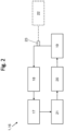
- Fig. 2 shows an embodiment of an oil circuit 16 of an internal combustion engine 1, for example as shown in Fig.1 shown combustion engine 1.
- This oil circuit 16 of the internal combustion engine 1 is shown schematically, wherein the arrows on the one hand indicate the flow direction of the engine oil in the oil circuit 16 and on the other hand symbolize the fluidic connection between the components, for example through an oil line.
- the engine oil is pumped from an oil pan 21 of the internal combustion engine 1, in which the engine oil collects, via an oil pump 20 to the oil cooler 19, which is provided to temper or cool the engine oil.
- the engine oil reaches the oil filter 18, through which suspended matter and particles are filtered out of the engine oil before the engine oil then enters the crankcase 17 of the internal combustion engine 1, where it serves to lubricate and/or cool the internal combustion engine 1 during the combustion process.
- the individual components of the oil circuit 16 are, for example, physically connected by a machine frame of the internal combustion engine 1.
- the sensor 23 which is designed to provide at least one numerical measured value 28 representative of the oil quality of the engine oil, which numerical measured value 28 can be provided to the control or regulating device 20 via a signal-conducting connection (represented by the dashed line).
- the sensor 23 is designed as a sensor which provides the numerical measurement value 28 via the electrical conductivity and/or permittivity of the engine oil, which is indicative of the oil quality of the engine oil.
- a sensor 23 can be implemented, for example, according to known embodiments of the prior art.
- the control or regulating device of this embodiment is designed to receive the numerical measured value 28 of the sensor 23 and to transform it into an absolute value 27.
- the absolute value 27 can, for example, reflect an oil quality of the engine oil via a percentage (0-100%).
- This derived quantity of the numerical measured value 28 (the absolute value 27) is compared with a condition 24 stored in the control or regulating device 22, wherein - if the measured value 28 of the sensor 23 satisfies the condition 24 - the measurement is continued and if the measured value 28 of the sensor 23 does not satisfy the condition 24, an oil sampling interval is adjusted depending on at least one numerical measured value 28 and/or the absolute value 27.
- the oil sampling interval is output in the form of message 31.
- This output of the message 31 by the control or regulating device 22 can be carried out via a display device of the control or regulating device 22.
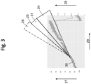
- Fig.3 graphically shows an embodiment according to the inventive method for monitoring the condition of a lubricant of the internal combustion engine 1.
- This graphic shows the relationship between measured values 28 of the sensor 23 with respect to operating hours 29 of the internal combustion engine 1 and which condition 24 can be stored in the control or regulating device 22.
- reference values 30 were determined which represent the acceptable ageing of an engine oil with regard to the operating hours 29 of the internal combustion engine 1.
- the numerical measured value 28 of the sensor 23 (which moves between a value of 0 and 1) has been converted into a derived quantity - the absolute value 27 of an oil quality of the engine oil (decreasing in the opposite direction from 100% to 0%).
- the reference values 30 of the normal ageing with respect to the operating hours 29 of the internal combustion engine 1 form an approximately linear function.
- This linear function defined condition 24, which represents a region.
- Condition 24 also took into account possible deviations in the measured values due to measurement inaccuracies as well as an acceptable fluctuation in oil quality.
- condition 24 which assigns a minimum and maximum permissible oil quality to each number of operating hours.
- control or regulating device 22 issues a corresponding message 31 in the form of an adjustment of the oil sampling interval.
- a tolerance range 25 can also be provided, wherein if this tolerance range 25 is exceeded, a critical message 26 can be issued by the control or regulating device 22.
- Such a critical message 26 of the control or regulating device 22 can, for example, result in the internal combustion engine 1 being shut down or in the restriction (for example of a line) of the internal combustion engine 1.
Landscapes
- Engineering & Computer Science (AREA)
- Mechanical Engineering (AREA)
- General Engineering & Computer Science (AREA)
- Lubrication Details And Ventilation Of Internal Combustion Engines (AREA)
Applications Claiming Priority (1)
| Application Number | Priority Date | Filing Date | Title |
|---|---|---|---|
| DE102023106324.3A DE102023106324A1 (de) | 2023-03-14 | 2023-03-14 | Verfahren zur Überwachung eines Schmierstoffes eines Verbrennungsmotors |
Publications (2)
| Publication Number | Publication Date |
|---|---|
| EP4431707A2 true EP4431707A2 (fr) | 2024-09-18 |
| EP4431707A3 EP4431707A3 (fr) | 2024-10-02 |
Family
ID=90361837
Family Applications (1)
| Application Number | Title | Priority Date | Filing Date |
|---|---|---|---|
| EP24161467.6A Pending EP4431707A3 (fr) | 2023-03-14 | 2024-03-05 | Procédé de surveillance d'un lubrifiant d'un moteur à combustion interne |
Country Status (4)
| Country | Link |
|---|---|
| US (1) | US12669075B2 (fr) |
| EP (1) | EP4431707A3 (fr) |
| CA (1) | CA3231877A1 (fr) |
| DE (1) | DE102023106324A1 (fr) |
Cited By (1)
| Publication number | Priority date | Publication date | Assignee | Title |
|---|---|---|---|---|
| US20240309783A1 (en) * | 2023-03-14 | 2024-09-19 | Innio Jenbacher Gmbh & Co Og | Condition based oil management |
Citations (3)
| Publication number | Priority date | Publication date | Assignee | Title |
|---|---|---|---|---|
| US20090315574A1 (en) | 2007-06-19 | 2009-12-24 | Akiyama Yo | Oil-degradation detecting apparatus |
| US20160003794A1 (en) | 2014-07-03 | 2016-01-07 | Caterpillar Inc. | Method of Detecting the Extent of Oil Degradation |
| US20200378283A1 (en) | 2019-06-03 | 2020-12-03 | Caterpillar Inc. | Systems and methods for remaining useful life prediction of a fluid |
Family Cites Families (14)
| Publication number | Priority date | Publication date | Assignee | Title |
|---|---|---|---|---|
| US6463796B1 (en) * | 2000-10-12 | 2002-10-15 | The Lubrizol Corporation | Continuous on-board diagnostic lubricant monitoring system and method |
| MXPA03009722A (es) * | 2001-04-26 | 2004-02-12 | Engineered Machined Products I | SISTEMA DE FILTRACIoN AUXILIAR Y METODO DE FILTRACIoN. |
| DE102004032344B4 (de) * | 2004-07-03 | 2012-02-23 | Robert Bosch Gmbh | Vorrichtung und Verfahren zur Steuerung einer Brennkraftmaschine |
| DE102005039480B4 (de) * | 2005-08-18 | 2011-04-07 | Continental Automotive Gmbh | Verfahren und Vorrichtung zur Messung eines Zustandes von Motoröl |
| US7293450B2 (en) * | 2005-10-05 | 2007-11-13 | Honeywell International Inc. | Oil quality sensor structure for permanent applications |
| DE102006059071A1 (de) * | 2006-12-14 | 2008-06-19 | Robert Bosch Gmbh | Verfahren zur Bestimmung der Ölqualität |
| US9244054B2 (en) * | 2012-07-10 | 2016-01-26 | GM Global Technology Operations LLC | Systems and methods for determining a state of deterioration of engine oil using multiple preselected oil properties |
| US9639091B2 (en) * | 2015-07-08 | 2017-05-02 | Caterpillar Inc. | System and method for collecting fluid sample from machine |
| US10466152B2 (en) * | 2015-10-07 | 2019-11-05 | Logilube, LLC | Fluid monitoring and management devices, fluid monitoring and management systems, and fluid monitoring and management methods |
| US10309276B2 (en) * | 2016-09-26 | 2019-06-04 | Caterpillar Inc. | On-engine fluid monitoring system |
| EP4097444A4 (fr) * | 2020-01-27 | 2024-03-06 | LogiLube, LLC | Procédés et dispositifs de surveillance de liquides de machine |
| DE102020004529A1 (de) * | 2020-07-27 | 2022-01-27 | Daimler Ag | Verfahren zum Überwachen eines Zustands eines Schmiermittels |
| US11982665B2 (en) * | 2020-11-20 | 2024-05-14 | Dodge Industrial, Inc. | Oil quality sensor |
| DE102023106324A1 (de) * | 2023-03-14 | 2024-09-19 | Innio Jenbacher Gmbh & Co Og | Verfahren zur Überwachung eines Schmierstoffes eines Verbrennungsmotors |
-
2023
- 2023-03-14 DE DE102023106324.3A patent/DE102023106324A1/de active Pending
-
2024
- 2024-03-05 EP EP24161467.6A patent/EP4431707A3/fr active Pending
- 2024-03-13 CA CA3231877A patent/CA3231877A1/en active Pending
- 2024-03-13 US US18/604,419 patent/US12669075B2/en active Active
Patent Citations (3)
| Publication number | Priority date | Publication date | Assignee | Title |
|---|---|---|---|---|
| US20090315574A1 (en) | 2007-06-19 | 2009-12-24 | Akiyama Yo | Oil-degradation detecting apparatus |
| US20160003794A1 (en) | 2014-07-03 | 2016-01-07 | Caterpillar Inc. | Method of Detecting the Extent of Oil Degradation |
| US20200378283A1 (en) | 2019-06-03 | 2020-12-03 | Caterpillar Inc. | Systems and methods for remaining useful life prediction of a fluid |
Cited By (2)
| Publication number | Priority date | Publication date | Assignee | Title |
|---|---|---|---|---|
| US20240309783A1 (en) * | 2023-03-14 | 2024-09-19 | Innio Jenbacher Gmbh & Co Og | Condition based oil management |
| US12669075B2 (en) * | 2023-03-14 | 2026-06-30 | Innio Jenbacher Gmbh & Co Og | Condition based oil management |
Also Published As
| Publication number | Publication date |
|---|---|
| US12669075B2 (en) | 2026-06-30 |
| US20240309783A1 (en) | 2024-09-19 |
| EP4431707A3 (fr) | 2024-10-02 |
| DE102023106324A1 (de) | 2024-09-19 |
| CA3231877A1 (en) | 2025-07-08 |
Similar Documents
| Publication | Publication Date | Title |
|---|---|---|
| DE102020126900B4 (de) | Verfahren zum Erfassen eines Ölzustands eines Betriebsöls, Steuer- und Regeleinrichtung sowie Brennkraftmaschine | |
| EP2417333B1 (fr) | Dispositif de surveillance et procédé de surveillance servant à surveiller un état d'usure d'un élément d'un moteur à combustion interne à piston alternatif | |
| EP1992935B1 (fr) | Procédé de fonctionnement d'un capteur à particules disposé en aval après un filtre à particules et dispositif d'exécution du procedée | |
| EP2927662B1 (fr) | Procédé et système de surveillance de l'état d'un palier de roulement d'une éolienne | |
| EP1892597A1 (fr) | Surveillance de machines et d'installations techniques | |
| EP1533669B1 (fr) | Surveillance d'état des processus techniques | |
| DE102017221318B4 (de) | Verfahren zur Dichtigkeitsprüfung einer Kurbelgehäuseentlüftungseinrichtung einer Brennkraftmaschine sowie Brennkraftmaschine für ein Kraftfahrzeug | |
| DE10001518B4 (de) | Verfahren zur Schmierung eines Zylinders in einem Verbrennungsmotor sowie ein Zylinderschmierungssystem und ein Verbindungselement | |
| EP0652426A1 (fr) | Méthode de reconnaissance des perturbations dans le functionnement d'un moteur à diesel | |
| CH708012A2 (de) | Turbomaschinenschmierölanalysesystem und Computerprogrammprodukt. | |
| DE19961064B4 (de) | Vorrichtung und Verfahren zum Detektieren von Fehlerzuständen für einen Verbrennungsmotor | |
| DE102022213206A1 (de) | Echtzeit-Überwachungsverfahren und Stabilitätsanalyseverfahren für ein Stranggießverfahren | |
| EP3940211A1 (fr) | Procédé de diagnostic pour une soupape de refroidissement à piston, dispositif de diagnostic, appareil de commande, véhicule automobile | |
| DE102007008968A1 (de) | Verfahren zum Erkennen von Wassereintrag in Dampfturbinen | |
| DE102023106324A1 (de) | Verfahren zur Überwachung eines Schmierstoffes eines Verbrennungsmotors | |
| DE10112691C5 (de) | Verfahren zum Betreiben eines Zweitakt-Großdieselmotors sowie Zweitakt-Großdieselmotor | |
| DE3700069C2 (de) | Schmiersystem | |
| DE102018104665B4 (de) | Verfahren zum Betrieb einer Brennkraftmaschine, Steuereinrichtung und Brennkraftmaschine | |
| WO2019077093A1 (fr) | Procédé et système destinés à évaluer un état de fonctionnement d'un véhicule nautique | |
| EP3891368B1 (fr) | Procédé permettant de déterminer et de prédire la périodicité individuelle des vidanges d'un moteur à combustion interne | |
| EP3980629B1 (fr) | Moteur à combustion interne et procédé pour faire fonctionner un tel moteur à combustion interne | |
| EP2282105A2 (fr) | Procédé de lubrification orientée vers la charge de systèmes tribologiques | |
| DE102005039480B4 (de) | Verfahren und Vorrichtung zur Messung eines Zustandes von Motoröl | |
| DE102016218937A1 (de) | Verfahren zum Betreiben eines Systems zur Durchführung eines thermodynamischen Kreisprozesses, System zur Durchführung eines thermodynamischen Kreisprozesses und Anordnung mit einem solchen System und einer Brennkraftmaschine | |
| EP1869448B1 (fr) | Procede de determination quantitative d'un effet du vieillissement sur une huile moteur |
Legal Events
| Date | Code | Title | Description |
|---|---|---|---|
| PUAI | Public reference made under article 153(3) epc to a published international application that has entered the european phase |
Free format text: ORIGINAL CODE: 0009012 |
|
| STAA | Information on the status of an ep patent application or granted ep patent |
Free format text: STATUS: THE APPLICATION HAS BEEN PUBLISHED |
|
| PUAL | Search report despatched |
Free format text: ORIGINAL CODE: 0009013 |
|
| AK | Designated contracting states |
Kind code of ref document: A2 Designated state(s): AL AT BE BG CH CY CZ DE DK EE ES FI FR GB GR HR HU IE IS IT LI LT LU LV MC ME MK MT NL NO PL PT RO RS SE SI SK SM TR |
|
| AK | Designated contracting states |
Kind code of ref document: A3 Designated state(s): AL AT BE BG CH CY CZ DE DK EE ES FI FR GB GR HR HU IE IS IT LI LT LU LV MC ME MK MT NL NO PL PT RO RS SE SI SK SM TR |
|
| RIC1 | Information provided on ipc code assigned before grant |
Ipc: F01M 11/10 20060101AFI20240827BHEP |
|
| STAA | Information on the status of an ep patent application or granted ep patent |
Free format text: STATUS: REQUEST FOR EXAMINATION WAS MADE |
|
| 17P | Request for examination filed |
Effective date: 20250225 |
|
| GRAP | Despatch of communication of intention to grant a patent |
Free format text: ORIGINAL CODE: EPIDOSNIGR1 |
|
| STAA | Information on the status of an ep patent application or granted ep patent |
Free format text: STATUS: GRANT OF PATENT IS INTENDED |
|
| INTG | Intention to grant announced |
Effective date: 20260611 |
|
| GRAS | Grant fee paid |
Free format text: ORIGINAL CODE: EPIDOSNIGR3 |
|
| GRAA | (expected) grant |
Free format text: ORIGINAL CODE: 0009210 |
|
| STAA | Information on the status of an ep patent application or granted ep patent |
Free format text: STATUS: THE PATENT HAS BEEN GRANTED |