EP4431770A2 - Dispositif de retenue de joint torique pour arme à feu à barre - Google Patents
Dispositif de retenue de joint torique pour arme à feu à barre Download PDFInfo
- Publication number
- EP4431770A2 EP4431770A2 EP24186510.4A EP24186510A EP4431770A2 EP 4431770 A2 EP4431770 A2 EP 4431770A2 EP 24186510 A EP24186510 A EP 24186510A EP 4431770 A2 EP4431770 A2 EP 4431770A2
- Authority
- EP
- European Patent Office
- Prior art keywords
- ring
- handle
- retaining
- dispensing device
- beverage dispensing
- Prior art date
- Legal status (The legal status is an assumption and is not a legal conclusion. Google has not performed a legal analysis and makes no representation as to the accuracy of the status listed.)
- Pending
Links
Images




Classifications
-
- B—PERFORMING OPERATIONS; TRANSPORTING
- B67—OPENING, CLOSING OR CLEANING BOTTLES, JARS OR SIMILAR CONTAINERS; LIQUID HANDLING
- B67D—DISPENSING, DELIVERING OR TRANSFERRING LIQUIDS, NOT OTHERWISE PROVIDED FOR
- B67D1/00—Apparatus or devices for dispensing beverages on draught
- B67D1/0042—Details of specific parts of the dispensers
- B67D1/0081—Dispensing valves
- B67D1/0085—Dispensing valves electro-mechanical
- B67D1/0086—Hand-held gun type valves
-
- B—PERFORMING OPERATIONS; TRANSPORTING
- B67—OPENING, CLOSING OR CLEANING BOTTLES, JARS OR SIMILAR CONTAINERS; LIQUID HANDLING
- B67D—DISPENSING, DELIVERING OR TRANSFERRING LIQUIDS, NOT OTHERWISE PROVIDED FOR
- B67D1/00—Apparatus or devices for dispensing beverages on draught
- B67D1/0042—Details of specific parts of the dispensers
- B67D1/0081—Dispensing valves
- B67D1/0082—Dispensing valves entirely mechanical
- B67D1/0083—Dispensing valves entirely mechanical with means for separately dispensing a single or a mixture of drinks
- B67D1/0084—Hand-held gun type valves
-
- B—PERFORMING OPERATIONS; TRANSPORTING
- B67—OPENING, CLOSING OR CLEANING BOTTLES, JARS OR SIMILAR CONTAINERS; LIQUID HANDLING
- B67D—DISPENSING, DELIVERING OR TRANSFERRING LIQUIDS, NOT OTHERWISE PROVIDED FOR
- B67D1/00—Apparatus or devices for dispensing beverages on draught
- B67D2001/0093—Valves
Definitions
- This specification relates to the field of beverage dispensing apparatus. More specifically, this application is directed toward systems and methods of an O-ring retaining apparatus for use in a bar gun.
- Such bar guns include O-rings to limit leakage of the various fluids out of the bar gun.
- U.S. Pat. 8,418,888 to Schroeder et. al shows an exemplary bar gun apparatus with approaches for the design of a backing plate that guides a valve stem for a valve in a bar gun, which is incorporated by.
- the present disclosure describes improved systems and methods directed toward the use of an O-ring retaining apparatus for use in a beverage dispensing apparatus such as a bar gun.
- the novel systems and methods in this disclosure enable a user of a bar gun to increase reliability of the O-ring seals in a bar gun, reducing leakage, reducing maintenance, and increasing service life of the bar gun.
- FIG. 1-4 A first embodiment of a system and method of using an O-ring retaining apparatus in a bar gun is shown in Figs. 1-4 .
- the apparatus comprises at least one plate rigidly fixed to the body of the bar gun handle to hold the O-rings in place when the bar gun is in operation and contains fluids under pressure.
- the plate may be made of various metals, may be of different shapes, or that there may be a plurality of plates to retain the O-rings in place, or the means to hold the plate rigidly fixed to the body may vary.
- Fig. 1 shows a partial exploded perspective view of a bar gun handle 100, which is a six-valve bar gun configured for a five-button control panel (not shown).
- the handle 100 is configured to accept six O-rings 102 with corresponding valve stems that proceed through holes in two retaining plates 103 as shown.
- the O-ring retaining plates 103 may be constructed of any suitable material, such as metal, plastic, food-grade plastic, other material.
- the retaining plates 103 are rigidly attached to the body 101 of the bar gun handle 100 by screws 104.
- retaining plates 103 are shown to be installed in a corresponding indentation in the exterior of body 101, but such configuration is not required. For example, there may be no indentation in body 101, or the indentation may be of different dimensions than of the retaining plates 103.
- Fig. 2 is a partial cross-sectional view of the bar gun handle 100 of Fig. 1 , showing the vertical plane passing through the valve stems (again, the bar gun's control panel is not shown).
- the installed retaining plate 103 sits on the surface of body 101 and is rigidly attached by screws 104 received in threaded holes or openings 104a in the body 101.
- a user may actuate a button on the control panel to open a valve, which in turns moves one or more valve stems up and down to dispense the desired liquid from the bar gun nozzle.
- O-rings 102 When a user depresses or releases the buttons, O-rings 102 are held in place in their respective indentations in body 101 by retaining plate 103 as the valve stems move up and down shown in Fig. 2 . Thus, the O-rings are retained in place.
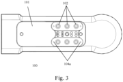
- Fig. 3 shows a top view of a partially-assembled embodiment of bar gun handle 100.
- Each of the O-rings 102 is shown installed in an indentation or cavity on the top of body 101, the cavity having roughly the same size as the O-rings.
- the top of the O-ring may be in close proximity or approximately level with the top surface of the bar gun handle's body 101.
- the installation of the O-rings 102 inside cavities on the top of body 101 is also shown in Fig. 2 .
- the four threaded holes 104a may be situated adjacent to the outermost O-ring indentations so as to receive the screws 104 for attaching the O-ring retaining plates 103, which are not shown in Fig. 3 .
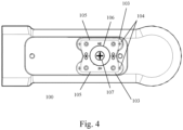
- Fig. 4 shows a top view of a partially-assembled embodiment of bar gun 100 with two butterfly plates 105, which are affixed by a washer 106 and screw 107, installed over the top of the O-ring retaining plates 103, which are affixed retain by screws 104.
- a button not shown in Fig. 4
- the button depresses one or both sides of the butterfly plate, which in turn actuates the valve stems shown in Fig. 1 and Fig. 2 .
- the screws 104 shown in Fig. 1 may be installed with thread locker, to inhibit their removal, or high adhesion stickers or caps may be affixed on top of them to inhibit access to the screws 104.
- a portion of the body of the bar gun handle may protrude up through the screw holes in the retaining plates 103.
- These protrusions may comprise posts of the material of construction of the body of the bar gun handle, such as food grade plastic.
- the posts may permanently deformed, such as by high heat, thus making it difficult to remove the retaining plate. If a retaining plate is removed, it cannot be permanently reinstalled, and its prior removal will be evidence during subsequent inspection.
- the retaining plates serve an anti-tamper feature in addition to retaining the O-rings in place during operation.
- FIG. 5-7 A second embodiment of a system and method of using an O-ring retaining apparatus in a bar gun is shown in Figs. 5-7 .
- the apparatus comprises at least one retaining clip inserted into the body of the bar gun handle to hold the O-rings in place when the bar gun is in operation and contains fluids under pressure.
- the O-ring retaining clip may be made of a semi-flexible material.
- semi-flexible refers to a material that is sufficiently flexible to be deformed by a stainless-steel tool, such as a flat-head screwdriver, but not manually by fingertips or fingernails.
- the O-ring retaining clip may be of different shapes and there may be a plurality of clips to retain the O-rings in place.
- Fig. 5 shows a partial exploded perspective view of a bar gun handle 200, which is a six-valve bar gun configured for a five-button control panel (not shown).
- the handle 200 is configured to accept six toric joints or O-rings 202 with corresponding valve stems that proceed through holes in two retaining clips 203.
- the six O-rings 202 may have D-shaped cross sections or other cross-sectional shapes known in the art.
- the O-ring retaining clips 203 may be constructed of any suitable semi-flexible material, such as plastic, food-grade plastic, or other material.
- the retaining clips 203 may be inserted into one or more openings located in the body 201 of the bar gun handle 200 to restrain the O-rings 202.
- Fig. 6 shows a perspective view of one embodiment of an O-ring retaining clip 203.
- the O-ring retaining claim 203 comprises an internal tab or flange 203a and an external tab or flange 203b.
- Fig. 7 shows an enlarged top perspective view of bar gun handle 200 having slots or openings in the body 201 adapted to accept an O-ring retaining clip 203.
- the body 201 may include an internal opening 204a and an external opening 204b to accommodate an O-ring retaining clip 203.
- the internal opening 204a is shaped to accept the corresponding internal tab 203a of an O-ring retaining clip 203
- the external opening 204b is shaped to accept the corresponding external tab 203b of O-ring retaining clip 203.
- the bar gun handle 200 includes two symmetric pairs of openings-an internal opening 204a and an external openings 204b for each of the two O-ring retaining clips 203.
- the semi-flexible O-ring retaining clips 203 may additionally be permanently or semi-permanently affixed to the body 201 of bar gun handle 200.
- the O-ring retaining clips 203 may be affixed to the body 101 of the bar gun handle 100 by heat welding or by glue, epoxies, or other by chemical adhesives.
- the disclosed O-ring retaining plate 103 and O-ring retaining clip 203 are not restricted to bar gun handles with only six valves, but that many alternatives are possible, including the number of valves.
- the disclosed O-ring retaining plates and O-ring retaining clips are not restricted to a bar gun handle with a control panel with only five buttons. Possible alternatives may include a control panel of any multiplicity of buttons.
Landscapes
- Engineering & Computer Science (AREA)
- Mechanical Engineering (AREA)
- Devices For Dispensing Beverages (AREA)
- Mechanically-Actuated Valves (AREA)
- Coating Apparatus (AREA)
- Automatic Assembly (AREA)
Applications Claiming Priority (3)
| Application Number | Priority Date | Filing Date | Title |
|---|---|---|---|
| US201962936194P | 2019-11-15 | 2019-11-15 | |
| EP20887457.8A EP4058396B1 (fr) | 2019-11-15 | 2020-11-16 | Un dispositif de distribution de boissons comprenant des clips de retenue de joint torique |
| PCT/US2020/060787 WO2021097451A1 (fr) | 2019-11-15 | 2020-11-16 | Appareil de retenue de joint torique pour un pistolet de bar |
Related Parent Applications (2)
| Application Number | Title | Priority Date | Filing Date |
|---|---|---|---|
| EP20887457.8A Division EP4058396B1 (fr) | 2019-11-15 | 2020-11-16 | Un dispositif de distribution de boissons comprenant des clips de retenue de joint torique |
| EP20887457.8A Division-Into EP4058396B1 (fr) | 2019-11-15 | 2020-11-16 | Un dispositif de distribution de boissons comprenant des clips de retenue de joint torique |
Publications (2)
| Publication Number | Publication Date |
|---|---|
| EP4431770A2 true EP4431770A2 (fr) | 2024-09-18 |
| EP4431770A3 EP4431770A3 (fr) | 2024-11-06 |
Family
ID=75908518
Family Applications (2)
| Application Number | Title | Priority Date | Filing Date |
|---|---|---|---|
| EP20887457.8A Active EP4058396B1 (fr) | 2019-11-15 | 2020-11-16 | Un dispositif de distribution de boissons comprenant des clips de retenue de joint torique |
| EP24186510.4A Pending EP4431770A3 (fr) | 2019-11-15 | 2020-11-16 | Dispositif de retenue de joint torique pour arme à feu à barre |
Family Applications Before (1)
| Application Number | Title | Priority Date | Filing Date |
|---|---|---|---|
| EP20887457.8A Active EP4058396B1 (fr) | 2019-11-15 | 2020-11-16 | Un dispositif de distribution de boissons comprenant des clips de retenue de joint torique |
Country Status (6)
| Country | Link |
|---|---|
| US (2) | US11390512B2 (fr) |
| EP (2) | EP4058396B1 (fr) |
| AU (1) | AU2020383688B2 (fr) |
| CA (1) | CA3160202C (fr) |
| MX (1) | MX2022005602A (fr) |
| WO (1) | WO2021097451A1 (fr) |
Families Citing this family (6)
| Publication number | Priority date | Publication date | Assignee | Title |
|---|---|---|---|---|
| US12503353B2 (en) * | 2019-11-15 | 2025-12-23 | Taprite Micro Matic, Inc. | O-ring retaining apparatus for a bar gun |
| USD987369S1 (en) * | 2021-10-20 | 2023-05-30 | Lancer Corporation | Bar gun |
| USD987370S1 (en) * | 2021-10-20 | 2023-05-30 | Lancer Corporation | Bar gun |
| USD987367S1 (en) * | 2021-10-20 | 2023-05-30 | Lancer Corporation | Bar gun |
| USD987368S1 (en) * | 2021-10-20 | 2023-05-30 | Lancer Corporation | Bar gun |
| WO2024264044A1 (fr) * | 2023-06-22 | 2024-12-26 | Taprite Micro Matic, Inc. | Appareil de retenue de joint torique pour pistolet de bar |
Citations (3)
| Publication number | Priority date | Publication date | Assignee | Title |
|---|---|---|---|---|
| US8387829B2 (en) | 2007-10-01 | 2013-03-05 | Schroeder Industries, Inc. | Nozzle assembly for a bar gun |
| US8418888B2 (en) | 2007-10-01 | 2013-04-16 | Schroeder Industries, Inc. | Backing plate assembly for a bar gun |
| US8770442B2 (en) | 2010-06-04 | 2014-07-08 | Schroeder Industries, Inc. | O-ring retainer for valve stem |
Family Cites Families (7)
| Publication number | Priority date | Publication date | Assignee | Title |
|---|---|---|---|---|
| US3168967A (en) * | 1961-10-03 | 1965-02-09 | Tony J Giampa | Beverage dispenser |
| US3703187A (en) * | 1970-12-11 | 1972-11-21 | Jack J Booth | Dispensing valve |
| US4986449A (en) * | 1988-08-12 | 1991-01-22 | Automatic Bar Controls, Inc. | Beverage dispensing apparatus |
| US5042692A (en) * | 1988-08-12 | 1991-08-27 | Automatic Bar Controls, Inc. | Beverage dispensing apparatus |
| US8272536B2 (en) * | 2007-11-21 | 2012-09-25 | Automatic Bar Controls, Inc. | Beverage dispensing apparatus with butterfly plates and a molded O-ring retainer |
| WO2011026012A1 (fr) * | 2009-08-28 | 2011-03-03 | Automatic Bar Controls, Inc. | Bouchon daccès verrouillable pour pistolet distributeur |
| US9706794B2 (en) | 2010-05-20 | 2017-07-18 | Automatic Bar Controls, Inc. | Ultraviolet disinfecting device for food and beverage dispensers |
-
2020
- 2020-11-16 MX MX2022005602A patent/MX2022005602A/es unknown
- 2020-11-16 US US17/099,580 patent/US11390512B2/en active Active
- 2020-11-16 CA CA3160202A patent/CA3160202C/fr active Active
- 2020-11-16 AU AU2020383688A patent/AU2020383688B2/en active Active
- 2020-11-16 WO PCT/US2020/060787 patent/WO2021097451A1/fr not_active Ceased
- 2020-11-16 EP EP20887457.8A patent/EP4058396B1/fr active Active
- 2020-11-16 EP EP24186510.4A patent/EP4431770A3/fr active Pending
-
2022
- 2022-06-17 US US17/807,477 patent/US11724929B2/en active Active
Patent Citations (3)
| Publication number | Priority date | Publication date | Assignee | Title |
|---|---|---|---|---|
| US8387829B2 (en) | 2007-10-01 | 2013-03-05 | Schroeder Industries, Inc. | Nozzle assembly for a bar gun |
| US8418888B2 (en) | 2007-10-01 | 2013-04-16 | Schroeder Industries, Inc. | Backing plate assembly for a bar gun |
| US8770442B2 (en) | 2010-06-04 | 2014-07-08 | Schroeder Industries, Inc. | O-ring retainer for valve stem |
Also Published As
| Publication number | Publication date |
|---|---|
| US11390512B2 (en) | 2022-07-19 |
| CA3160202A1 (fr) | 2021-05-20 |
| CA3160202C (fr) | 2024-01-02 |
| EP4431770A3 (fr) | 2024-11-06 |
| WO2021097451A1 (fr) | 2021-05-20 |
| AU2020383688A1 (en) | 2022-06-02 |
| EP4058396B1 (fr) | 2025-02-26 |
| US20220388830A1 (en) | 2022-12-08 |
| AU2020383688B2 (en) | 2026-02-19 |
| US20210147208A1 (en) | 2021-05-20 |
| EP4058396C0 (fr) | 2025-02-26 |
| US11724929B2 (en) | 2023-08-15 |
| EP4058396A1 (fr) | 2022-09-21 |
| EP4058396A4 (fr) | 2023-12-06 |
| MX2022005602A (es) | 2022-08-15 |
Similar Documents
| Publication | Publication Date | Title |
|---|---|---|
| US11724929B2 (en) | O-ring retaining apparatus for a bar gun | |
| US12344457B2 (en) | Can tap | |
| US8087545B2 (en) | Counter mounted dispensing system | |
| US20250340421A1 (en) | O-ring retaining apparatus for a bar gun | |
| US20150108176A1 (en) | Can tap | |
| US9463968B2 (en) | Faucet assembly | |
| US3454199A (en) | Keg tapping structure | |
| CN111148717A (zh) | 分配系统 | |
| AU2024313621A1 (en) | O-ring retaining apparatus for a bar gun | |
| JP2022507185A (ja) | 分注ヘッドおよび飲料分注システム | |
| EP1627850A1 (fr) | Raccord pour robinet distributeur | |
| US20160257552A1 (en) | Adjustment mechanism for a beverage tap handle | |
| US20140191001A1 (en) | System and Method for Timer Actuation of Aerosol Canisters | |
| RU2792963C2 (ru) | Раздаточная головка, система раздачи напитков, способы активации и дезактивации раздаточной головки | |
| US20210323806A1 (en) | Quick release beverage dispenser with keyed coupler | |
| US20150225132A1 (en) | Fluid outlet system | |
| US20060124884A1 (en) | Valve for liquid dispensing system | |
| HK40055977A (en) | A dispense head and beverage dispensing system | |
| WO2005012158A1 (fr) | Soupape a bec munie d'un systeme anti-eclatement | |
| HK40055977B (en) | A dispense head and beverage dispensing system | |
| WO2006084029A1 (fr) | Ensemble de bec verseur | |
| CA2441019A1 (fr) | Robinet de systeme de distribution de liquide |
Legal Events
| Date | Code | Title | Description |
|---|---|---|---|
| PUAI | Public reference made under article 153(3) epc to a published international application that has entered the european phase |
Free format text: ORIGINAL CODE: 0009012 |
|
| STAA | Information on the status of an ep patent application or granted ep patent |
Free format text: STATUS: THE APPLICATION HAS BEEN PUBLISHED |
|
| AC | Divisional application: reference to earlier application |
Ref document number: 4058396 Country of ref document: EP Kind code of ref document: P |
|
| AK | Designated contracting states |
Kind code of ref document: A2 Designated state(s): AL AT BE BG CH CY CZ DE DK EE ES FI FR GB GR HR HU IE IS IT LI LT LU LV MC MK MT NL NO PL PT RO RS SE SI SK SM TR |
|
| REG | Reference to a national code |
Ref country code: DE Ref legal event code: R079 Free format text: PREVIOUS MAIN CLASS: F16K0011140000 Ipc: B67D0001000000 |
|
| PUAL | Search report despatched |
Free format text: ORIGINAL CODE: 0009013 |
|
| AK | Designated contracting states |
Kind code of ref document: A3 Designated state(s): AL AT BE BG CH CY CZ DE DK EE ES FI FR GB GR HR HU IE IS IT LI LT LU LV MC MK MT NL NO PL PT RO RS SE SI SK SM TR |
|
| RIC1 | Information provided on ipc code assigned before grant |
Ipc: F16K 11/14 20060101ALI20240927BHEP Ipc: F16K 11/10 20060101ALI20240927BHEP Ipc: B67D 7/78 20100101ALI20240927BHEP Ipc: F16K 41/04 20060101ALI20240927BHEP Ipc: F16K 41/06 20060101ALI20240927BHEP Ipc: B67D 1/00 20060101AFI20240927BHEP |
|
| RAP3 | Party data changed (applicant data changed or rights of an application transferred) |
Owner name: MICRO MATIC, INC. |
|
| STAA | Information on the status of an ep patent application or granted ep patent |
Free format text: STATUS: REQUEST FOR EXAMINATION WAS MADE |
|
| 17P | Request for examination filed |
Effective date: 20250506 |
|
| STAA | Information on the status of an ep patent application or granted ep patent |
Free format text: STATUS: EXAMINATION IS IN PROGRESS |
|
| 17Q | First examination report despatched |
Effective date: 20250807 |
|
| RAP3 | Party data changed (applicant data changed or rights of an application transferred) |
Owner name: TAPRITE MICRO MATIC, INC. |