EP4431783B1 - Revetement tubulaire - Google Patents
Revetement tubulaire Download PDFInfo
- Publication number
- EP4431783B1 EP4431783B1 EP23162294.5A EP23162294A EP4431783B1 EP 4431783 B1 EP4431783 B1 EP 4431783B1 EP 23162294 A EP23162294 A EP 23162294A EP 4431783 B1 EP4431783 B1 EP 4431783B1
- Authority
- EP
- European Patent Office
- Prior art keywords
- liner
- layer
- fibrous layer
- material sheet
- fibres
- Prior art date
- Legal status (The legal status is an assumption and is not a legal conclusion. Google has not performed a legal analysis and makes no representation as to the accuracy of the status listed.)
- Active
Links
Images

Classifications
-
- F—MECHANICAL ENGINEERING; LIGHTING; HEATING; WEAPONS; BLASTING
- F16—ENGINEERING ELEMENTS AND UNITS; GENERAL MEASURES FOR PRODUCING AND MAINTAINING EFFECTIVE FUNCTIONING OF MACHINES OR INSTALLATIONS; THERMAL INSULATION IN GENERAL
- F16L—PIPES; JOINTS OR FITTINGS FOR PIPES; SUPPORTS FOR PIPES, CABLES OR PROTECTIVE TUBING; MEANS FOR THERMAL INSULATION IN GENERAL
- F16L55/00—Devices or appurtenances for use in, or in connection with, pipes or pipe systems
- F16L55/16—Devices for covering leaks in pipes or hoses, e.g. hose-menders
- F16L55/162—Devices for covering leaks in pipes or hoses, e.g. hose-menders from inside the pipe
- F16L55/165—Devices for covering leaks in pipes or hoses, e.g. hose-menders from inside the pipe a pipe or flexible liner being inserted in the damaged section
- F16L55/1656—Devices for covering leaks in pipes or hoses, e.g. hose-menders from inside the pipe a pipe or flexible liner being inserted in the damaged section materials for flexible liners
-
- B—PERFORMING OPERATIONS; TRANSPORTING
- B29—WORKING OF PLASTICS; WORKING OF SUBSTANCES IN A PLASTIC STATE IN GENERAL
- B29C—SHAPING OR JOINING OF PLASTICS; SHAPING OF MATERIAL IN A PLASTIC STATE, NOT OTHERWISE PROVIDED FOR; AFTER-TREATMENT OF THE SHAPED PRODUCTS, e.g. REPAIRING
- B29C63/00—Lining or sheathing, i.e. applying preformed layers or sheathings of plastics; Apparatus therefor
- B29C63/26—Lining or sheathing of internal surfaces
- B29C63/34—Lining or sheathing of internal surfaces using tubular layers or sheathings
-
- B—PERFORMING OPERATIONS; TRANSPORTING
- B29—WORKING OF PLASTICS; WORKING OF SUBSTANCES IN A PLASTIC STATE IN GENERAL
- B29C—SHAPING OR JOINING OF PLASTICS; SHAPING OF MATERIAL IN A PLASTIC STATE, NOT OTHERWISE PROVIDED FOR; AFTER-TREATMENT OF THE SHAPED PRODUCTS, e.g. REPAIRING
- B29C70/00—Shaping composites, i.e. plastics material comprising reinforcements, fillers or preformed parts, e.g. inserts
- B29C70/04—Shaping composites, i.e. plastics material comprising reinforcements, fillers or preformed parts, e.g. inserts comprising reinforcements only, e.g. self-reinforcing plastics
- B29C70/06—Fibrous reinforcements only
- B29C70/10—Fibrous reinforcements only characterised by the structure of fibrous reinforcements, e.g. hollow fibres
- B29C70/16—Fibrous reinforcements only characterised by the structure of fibrous reinforcements, e.g. hollow fibres using fibres of substantial or continuous length
- B29C70/22—Fibrous reinforcements only characterised by the structure of fibrous reinforcements, e.g. hollow fibres using fibres of substantial or continuous length oriented in at least two directions forming a two-dimensional [2D] structure
-
- F—MECHANICAL ENGINEERING; LIGHTING; HEATING; WEAPONS; BLASTING
- F16—ENGINEERING ELEMENTS AND UNITS; GENERAL MEASURES FOR PRODUCING AND MAINTAINING EFFECTIVE FUNCTIONING OF MACHINES OR INSTALLATIONS; THERMAL INSULATION IN GENERAL
- F16L—PIPES; JOINTS OR FITTINGS FOR PIPES; SUPPORTS FOR PIPES, CABLES OR PROTECTIVE TUBING; MEANS FOR THERMAL INSULATION IN GENERAL
- F16L11/00—Hoses, i.e. flexible pipes
- F16L11/04—Hoses, i.e. flexible pipes made of rubber or flexible plastics
- F16L11/08—Hoses, i.e. flexible pipes made of rubber or flexible plastics with reinforcements embedded in the wall
- F16L11/085—Hoses, i.e. flexible pipes made of rubber or flexible plastics with reinforcements embedded in the wall comprising one or more braided layers
-
- B—PERFORMING OPERATIONS; TRANSPORTING
- B29—WORKING OF PLASTICS; WORKING OF SUBSTANCES IN A PLASTIC STATE IN GENERAL
- B29C—SHAPING OR JOINING OF PLASTICS; SHAPING OF MATERIAL IN A PLASTIC STATE, NOT OTHERWISE PROVIDED FOR; AFTER-TREATMENT OF THE SHAPED PRODUCTS, e.g. REPAIRING
- B29C2793/00—Shaping techniques involving a cutting or machining operation
- B29C2793/0063—Cutting longitudinally
-
- B—PERFORMING OPERATIONS; TRANSPORTING
- B29—WORKING OF PLASTICS; WORKING OF SUBSTANCES IN A PLASTIC STATE IN GENERAL
- B29C—SHAPING OR JOINING OF PLASTICS; SHAPING OF MATERIAL IN A PLASTIC STATE, NOT OTHERWISE PROVIDED FOR; AFTER-TREATMENT OF THE SHAPED PRODUCTS, e.g. REPAIRING
- B29C2793/00—Shaping techniques involving a cutting or machining operation
- B29C2793/0072—Shaping techniques involving a cutting or machining operation combined with rearranging and joining the cut parts
-
- B—PERFORMING OPERATIONS; TRANSPORTING
- B29—WORKING OF PLASTICS; WORKING OF SUBSTANCES IN A PLASTIC STATE IN GENERAL
- B29K—INDEXING SCHEME ASSOCIATED WITH SUBCLASSES B29B, B29C OR B29D, RELATING TO MOULDING MATERIALS OR TO MATERIALS FOR MOULDS, REINFORCEMENTS, FILLERS OR PREFORMED PARTS, e.g. INSERTS
- B29K2105/00—Condition, form or state of moulded material or of the material to be shaped
- B29K2105/06—Condition, form or state of moulded material or of the material to be shaped containing reinforcements, fillers or inserts
- B29K2105/08—Condition, form or state of moulded material or of the material to be shaped containing reinforcements, fillers or inserts of continuous length, e.g. cords, rovings, mats, fabrics, strands or yarns
- B29K2105/10—Cords, strands or rovings, e.g. oriented cords, strands or rovings
- B29K2105/101—Oriented
-
- B—PERFORMING OPERATIONS; TRANSPORTING
- B29—WORKING OF PLASTICS; WORKING OF SUBSTANCES IN A PLASTIC STATE IN GENERAL
- B29L—INDEXING SCHEME ASSOCIATED WITH SUBCLASS B29C, RELATING TO PARTICULAR ARTICLES
- B29L2023/00—Tubular articles
- B29L2023/001—Tubular films, sleeves
Definitions
- the invention relates to a tubular liner for the rehabilitation of pipelines and channels, a cured liner, a method for producing a liner, the use of the liner, a method for the rehabilitation of pipelines and channels, and a rehabilitated pipeline or channel.
- Fibers can generally be aligned in the circumferential direction, i.e. perpendicular to the longitudinal direction of the liner, in order to improve the mechanical properties of the liner in the circumferential direction. To date, this has been done by either aligning very short fiber sections in the circumferential direction, which were usually laid overlapping. Such liners then often have a longitudinal seam and are therefore less stretchable in the circumferential direction.
- US6615875B2 describes a liner for reinforcing a pipe and a method for producing the same.
- the object of the present invention is therefore to overcome these disadvantages of the prior art and to provide a technology with which liners can be obtained which have good mechanical properties even in the circumferential direction and are nevertheless sufficiently elastic to better adhere to the old pipe of the lines to be renovated.
- a tubular liner for the rehabilitation of pipes and channels which comprises resin-impregnated fiber layers, wherein at least one fiber layer is a transverse fiber layer which (predominantly) has fibers which are arranged at an angle in a range of 45° to 135° relative to the longitudinal direction of the liner, wherein these fibers of the transverse fiber layer arranged in this way predominantly have a median length in a range of 20 to 50% of the circumference of the liner.
- a mat can consist of a layer of direct roving, a cross-fiber layer and a layer of cut roving. These layers can be sewn together.
- the liner according to the invention has the advantage that this liner is more flexible and requires less working pressure.
- Working pressure in the sense of the invention is the pressure that is maintained during installation in order to press the liner onto the old pipe.
- the liner has the advantage of increased flexibility that side inlets such as house connections can be seen in the renovated pipe ("dimpling") and can thus be identified more easily.
- Outside in the sense of the invention means the inner wall of the pipe facing the pipe or channel to be renovated.
- Inside in the sense of the invention means the inner wall of the pipe facing away from the pipe or channel to be renovated. This is important because there are, for example, so-called pull-in liners, where the outermost layer is on the outside before and after installation. But there are also so-called inversion liners, where an initially internal layer in the renovated pipe or channel is on the outside.
- the liner can have at least one outer layer (for example, light protection film, outer film, etc.).
- the outer layer can have a monomer barrier layer. This monomer barrier layer is intended to prevent the diffusion of reactive diluents such as styrene from uncured resin systems.
- the outer layer preferably has a thickness in the range of 40 to 2000 ⁇ m.
- the outer layer is advantageously not permeable to UV radiation so that the resin system in the resin-impregnated fiber layer does not harden, for example during storage or transport.
- the outer layer can consist of polymer, for example, or of a fleece with polymer laminated on. Examples of materials for the polymer and/or fleece include polyester, polyamide, polyvinyl chloride, polyacrylonitrile, polyethylene, polypropylene and/or mixtures thereof.
- the liner can have at least one anchoring layer.
- the anchoring layer which preferably consists of a thermoplastic material, in turn preferably has a thickness in a range of 10 to 5000 ⁇ m, in particular 30 to 500 ⁇ m.
- the anchoring layer advantageously consists of a fleece or a hot melt adhesive or a combination of these variants.
- the fleece is particularly preferably made of glass, thermoplastic materials, PAN, or mixtures thereof.
- the thermoplastic materials are selected, for example, from polyethylene, polypropylene or polyester.
- the hot melt adhesive is, for example, polyamide, polyethylene, APAO (amorphous polyolefin), EVAC (ethylene vinyl acetate copolymer), TPE-E (polyester elastomer), TPE-U (polyurethane elastomer), TPE-A (copolyamide elastomer) or vinylpyrrolidone/vinyl acetate copolymer, as well as mixtures thereof.
- the liner can have an inner layer.
- the inner layer can have a monomer barrier layer.
- the inner layer advantageously has a thickness in a range of 100 to 1500 ⁇ m. In particular, the inner layer has a thickness in a range of 100 to 600 ⁇ m. This means that this inner layer can be protected from mechanical damage, for example from the device for curing the resin-impregnated fiber layer, but is still thin enough to allow enough heat or UV radiation to pass through for curing.
- This inner layer advantageously has several layers. One of these layers is, for example, a monomer barrier layer. This monomer barrier layer is intended to prevent the diffusion of reactive diluents such as styrene from uncured resin systems.
- This monomer barrier layer is advantageously one of the layers of the inner layer that is not on the outside ("outside” here means “visible to the viewer” and/or "adjacent to the anchoring layer”).
- the monomer barrier layer contains, for example, at least 50% by weight and particularly preferably consists of polyamide, ethylene-vinyl alcohol copolymer, PBT, PET, halogenated polymers or mixtures thereof.
- the monomer barrier layer particularly preferably consists of one or more of these materials.
- the monomer barrier layer advantageously has a thickness in a range from 10 to 500 ⁇ m.
- the inner layer advantageously has at least one and advantageously two outer layers (“outer” here means “visible to the observer” and/or “adjacent to the anchoring layer”) made of polyurethane, polyethylene or polypropylene.
- This outer layer advantageously has a thickness in a range of 50 to 1000 ⁇ m.
- the outer layer adjacent to the anchoring layer for example as an adhesive layer
- the other outer layer that faces the middle of the hose namely, for example, a wear layer. This allows the inner layer to provide even better protection against mechanical influences.
- At least the anchoring layer and the inner layer are connected to one another in a material-locking or force-locking manner. Because at least these two layers are preferably connected to one another in a material-locking or force-locking manner, these layers cannot move relative to one another. This significantly improves the stability of the entire layer structure. Furthermore, the inner layer is considerably reinforced by the anchoring layer connected to it, so that the inner layer can no longer be easily damaged.
- material-locking or force-locking can advantageously mean that the respective layers are either fully or partially laminated, bonded or glued to one another. If the layers are partially bonded to one another, preferably at least 40% of the surface area of the layers is bonded to one another or alternatively bonded at certain points. In this way, slipping of the layers against one another can be completely avoided.
- the layers can additionally or alternatively be bonded in such a way that a highly flowable thermoplastic material is extruded between the layers during production.
- a layer of polyethylene, polypropylene or polyurethane is located right inside towards the middle of the pipe as the outer layer of the inner layer.
- the monomer barrier layer is advantageously located next to this as the layer of the inner layer.
- a layer of A layer of polyethylene or polypropylene may be provided as an additional layer of the inner layer.
- the liner can have several fiber layers and at least one of these cross fiber layers.
- the fibers may preferably be fibers made of glass, carbon, polymer, cellulose or mixtures thereof, but most preferably glass.
- the fiber layers or at least one fiber layer can consist of material webs that are connected to one another at their longitudinal edges. This connection can be made, for example, by sewing or needling. In this way, tubular fiber layers can be created.
- the fiber layers can also simply be laid together in an overlapping manner to form a tubular structure without being connected in the overlapping area.
- the outermost fiber layer facing the inner wall of the pipe is connected to one another at its longitudinal edges (for example by overlapping and then needling).
- At least one mat can also be connected to one another at the longitudinal edge.
- the outermost mat facing the inner wall of the pipe is connected to one another at its longitudinal edges (for example by overlapping and then needling).
- a mat can have several fiber layers. These fiber layers can be, for example, cross fiber layers, layers of direct roving or layers of cut roving.
- a mat can also consist of at least one material web, in which case the material web can comprise several fiber layers.
- the adjacent fiber layers or adjacent mats can differ from each other in that the longitudinal edges of the material webs are offset.
- the fibers can, for example, consist of bundles of filaments.
- the fiber layer is preferably a scrim, a woven fabric, a random fiber mat, a knitted fabric, a fleece, a felt, a warp-knitted fabric or a combination or a multi-layer structure of these textile fabrics.
- a cross fiber layer can also contain cut roving in the same layer.
- a fiber layer can also contain different types of fibers (for example polymer fibers, glass fibers, carbon fibers, etc.).
- a fleece can be combined with a scrim in one layer.
- the mats can preferably each have a basis weight in a range of 200 to 3000 g/m 2 , more preferably in a range of 400 to 2600 g/m 2 , and most preferably in a range of 700 to 1800 g/m 2 .
- the fiber layers can preferably each have a basis weight in a range of 50 to 1000 g/m 2 , more preferably in a range of 100 to 900 g/m 2 , and most preferably in a range of 200 to 600 g/m 2 .
- the liner can preferably have 1 to 20 mats, particularly preferably 2 to 15 mats.
- the liner can preferably have 3 to 60 fiber layers, particularly preferably 6 to 45 fiber layers.
- the material for the resin system can be selected from the group of unsaturated polyester resins, vinyl ester resins, epoxy resins, or mixtures thereof.
- the resin system is preferably not or only partially polymerized (before installation). After installation, the resin can be polymerized.
- the composition of the resin system advantageously contains 0.1 to 20 parts by weight of a thickening agent (such as isocyanate, metal hydroxides, metal oxides such as magnesium oxide or calcium oxide or minerals such as kaolin or mixtures thereof) and in particular an isocyanate based on 100 parts by weight of resin system. It has been found that this allows the composition of the resin system to be resin system, but is liquid enough during manufacture to completely saturate the anchor layer or the inner fleece and the fiber layer.
- a thickening agent such as isocyanate, metal hydroxides, metal oxides such as magnesium oxide or calcium oxide or minerals such as kaolin or mixtures thereof
- At least the outermost fiber layer or mat is preferably joined at the longitudinal edge (for example overlapping and needled or glued or quilted or sewn).
- the outermost mat comprises a scrim that is needled.
- the outermost mat may, but need not, contain a cross-fiber layer.
- At least one of the fiber layers is a transverse fiber layer.
- the at least one transverse fiber layer preferably differs (predominantly) from an adjacent fiber layer in the arrangement of the fibers, the material of the fibers, the median length of the fibers and/or the basis weight of adjacent layers.
- the at least one transverse fiber layer can also differ from an adjacent fiber layer in that the connection or overlap (or overlap and connection) of the longitudinal edges of the material webs is offset in the circumferential direction.
- the transverse fiber layer predominantly (particularly preferably at least 60% by weight) comprises fibers which are arranged at an angle in a range of 45° to 135°, particularly preferably from 80° to 100°, relative to the longitudinal direction of the liner.
- the basis weight of these fibers in the transverse fiber layer can preferably be in a range of 50 to 1000 g/m 2 .
- the cross-fiber layer or the mat can also have fibers that are aligned at +20° to -20° relative to the longitudinal direction.
- the basis weight of these fibers in the cross-fiber layer or mat can preferably be in a range of 50 to 1000 g/m 2 .
- the cross-fibre layer or mat may also contain cut roving (e.g. CSM).
- the basis weight of these fibres in the cross-fibre layer or mat may preferably be in a range of 50 to 1000 g/m 2 .
- the cross-fiber layer or mat can preferably comprise a scrim.
- the scrim preferably has a width in a range of 90 to 110% of the circumference of the liner.
- the scrim preferably has the length of the liner.
- the liner can also consist of several connected scrims.
- the scrim is preferably connected to one another at both longitudinal edges of the scrim (for example by sewing or needling, either butt-jointed or overlapping), particularly if it is the outermost cross-fiber layer. This creates a tubular cross-fiber layer or mat.
- At least one transverse fiber layer preferably has predominantly (particularly preferably at least 50% by weight, very particularly preferably at least 60% by weight) fibers which are aligned at an angle in a range from 45° to 135° relative to the longitudinal direction of the liner and which are severed at at least one point, preferably at least 2 points, more preferably at 1 to 10 points, per fiber.
- These severing points are preferably at a distance from the fiber end in a range from 5 to 100 cm, particularly preferably in a range from 10 to 50 cm.
- These severing points are preferably at a distance from the fiber end in a range from 2 to 20% of the circumference of the liner, particularly preferably in a range from 5 to 15% of the circumference of the liner.
- the severances (for example cuts) can also be arranged randomly and have a random length. The number of severances per area and length of the severances reaches its limit where the material can no longer be processed.
- the severances (such as cuts) are grouped.
- the fibers of the cross fiber layer are preferably separated by Cuts in the longitudinal direction of the liner, each with a length of 0.5 to 50 cm.
- the fibers of the transverse fiber layer are severed, for example, over a length of 0.5 to 50 cm, particularly preferably 2 to 10 cm, for example by cuts in the longitudinal direction of the liner at the same point in the circumferential direction.
- At the same point in the circumferential direction means that there is essentially a cutting line in the direction of the length of the liner with cuts that lie on this cutting line. This can be achieved, for example, by cutting tools that are lowered into the fibers with the cutting tool and then removed from the fibers again. This can be done, for example, by cuts through the fibers of the transverse fiber layer in the longitudinal direction of the liner.
- the separations or cuts can lie along one or more cutting lines, which preferably run in the longitudinal direction of the liner (the cutting lines can also have a different angle).
- the fibers of the transverse fiber layer can be severed along a cutting line in evenly or unevenly arranged cuts. Neighboring cuts with a cutting length are preferably spaced apart by one distance length.
- the median of the distance length of the cuts along a cutting line is preferably shorter than the median of the cutting length of the cuts.
- the median of the distance length is preferably in a range of 20 to 70% of the median of the cutting length.
- the positions in the circumferential direction of the cuts (or cuts) of the groupings of the cuts adjacent in the longitudinal direction of the liner are preferably spaced apart by 10 to 40% of the circumference of the liner.
- the number of cutting lines in the longitudinal direction of the liner is preferably in a range of 1 to 12, very particularly preferably in a range of 2 to 6.
- the cutting lines preferably do not run in a fold in the longitudinal direction of the liner.
- the at least one cross fiber layer may, but does not have to, be the outermost fiber layer.
- a cross fiber layer may also additionally or alternatively be one of the other fiber layers of a mat.
- the transverse fiber layer preferably comprises at least 50% by weight, particularly preferably at least 60% by weight, of fibers arranged at an angle in a range of 45° to 135°, particularly preferably 80° to 100°, relative to the longitudinal direction of the liner.
- the cross-fiber layer is also resin-impregnated.
- the object underlying the invention is achieved by a cured liner, characterized in that the resin system of the resin-impregnated liner according to the invention is cured.
- cured can be understood to mean that the residual styrene content is below 10% by weight based on pure resin.
- a cross-fiber layer can also already be formed.
- the cuts in step c. can preferably be made in the longitudinal direction of the liner. However, they can also be made in another direction.
- the long edges of the other material web can be connected, for example, by needling or sewing.
- the long edges can be connected overlappingly or butt-jointed.
- the dry goods of the liner can be created, for example.
- the inner layer can preferably be provided with an anchoring layer (particularly preferably laminated).
- the cuts can be made while laying a layer of fibers or later, when the layer has already been turned into a material web.
- the cuts can be made using mechanical knives, scissors, but also lasers or ultrasonic knives.
- the object underlying the invention is achieved by using the liner according to the invention for rehabilitating pipelines or channels.
- the object underlying the invention is achieved by a method for rehabilitating pipelines or channels, characterized in that a liner according to the invention is introduced into a pipeline or channel to be rehabilitated and the liner is cured in the pipeline or channel.
- the curing can be done, for example, using UV light or thermally.
- the object underlying the invention is achieved by a rehabilitated pipeline or channel, characterized in that the pipeline or channel has a liner according to the invention (cured or uncured).
- Fig. 1 shows a liner 10 with an outer layer 110, the fiber layers 20, of which the outer fiber layer is a cross fiber layer 30.
- the inner layer 120 can be a polymer film which is laminated on its inside with an anchoring layer 130 such as a polyester fleece.
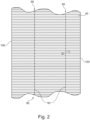
- Fig. 2 shows the further material web 90.
- a tubular cross-fiber layer 30 is created by connecting the longitudinal edges 100. This lies for example, right on the outside.
- the longitudinal edges can be connected by needling after they have been laid overlapping one another.
- the fibers of the transverse fiber layer 40 are severed along cutting lines 60 with the aid of cuts 50.
- the cutting length 70 is longer than the spacing length 80.
- the cuts 50 of the various cutting lines 60 are arranged offset so that the fibers of the transverse fiber layer 40 are severed at least once in each case.
- the liners or lining tubes according to the invention can be obtained by methods known per se and described in the literature. If the method is not described in more detail below, it can be assumed that the person skilled in the art will adhere to the methods known per se and known in the literature.
- direct roving strands (continuous fibers, 0° fabric) made of glass fiber were inserted lengthwise at a distance of 1 cm with a total basis weight of 600 g/m 2. Glass fibers were evenly placed on top of this at an angle of 90° with a basis weight of 600 g/m 2 (90° fabric). At this stage of production, this 90° fabric still has a length of 300 cm, i.e. the width of the scrim.
- Cutting roving (CSM) with a basis weight of 600 g/m 2 was placed on top in a random orientation so that the individual fiber sections of the cutting roving were in all possible directions. To obtain the cutting roving, the direct roving was cut into 10 cm long sections. The three fiber layers were then sewn together to form a mat with polyester yarn.
- CSM Cutting roving
- rotating knives were installed at intervals of 20 cm, which penetrated the passing mat at regular intervals on the side of the direct roving just far enough to make cuts in the 90° fabric about 10 cm long, each 5 cm apart, along a cutting line.
- the rotating knives were set in such a way that the neighboring rotating knives always made a cut in the 90° fabric when the neighboring rotating knife was outside the mat for the 5 cm distance. This ensured that each fiber of the 90° fabric was cut multiple times. This is how the cross-fiber layer was obtained.
- a polymer tube was introduced into a system for producing the dry material.
- This polymer tube consisted essentially of polymer and had a diameter of 85 cm. However, it also had a standard styrene barrier (PE/PA/PE).
- PE/PA/PE standard styrene barrier
- the uncut mat was placed around this tube so that it overlapped at the long edges, there was not too much play between the polymer tube and the mat, and so that the direct roving was placed adjacent to the tube.
- the second mat with the cut 90° material was then placed around this first mat so that the direct roving was on the outside. The long edges were overlapped so that the mat could be placed around the first mat without too much play, and needled in the overlap area.
- the dry material thus produced was impregnated with a UP resin containing a photoinitiator that is common for sewer rehabilitation liners.
- a tube like the inner polymer tube with a styrene barrier was then pulled around the soaked liner.
- the last layer was a standard gray outer film that does not allow light and UV radiation to pass through and is mechanically stable.
Landscapes
- Engineering & Computer Science (AREA)
- General Engineering & Computer Science (AREA)
- Mechanical Engineering (AREA)
- Textile Engineering (AREA)
- Chemical & Material Sciences (AREA)
- Composite Materials (AREA)
- Manufacturing & Machinery (AREA)
- Laminated Bodies (AREA)
Claims (13)
- Revêtement tubulaire (10) pour la réhabilitation de canalisations ou de conduits, le revêtement comprenant des couches de fibres imprégnées de résine (20), dans lequel au moins une couche de fibres est une couche de fibres transversales (30) comprenant principalement des fibres disposées à un angle dans une plage de 45° à 135° par rapport à la direction longitudinale du revêtement (10), caractérisé en ce que ces fibres de la couche de fibres transversales (40) ainsi disposées ont une longueur médiane comprise entre 20 et 50 % du contour du revêtement (10).
- Revêtement (10) selon la revendication 1, caractérisé en ce que la couche de fibres transversales (30) comprend principalement des fibres (40) disposées selon un angle compris entre 80° et 100° par rapport à la direction longitudinale du revêtement (10).
- Revêtement (10) selon l'une quelconque des revendications précédentes, caractérisé en ce que l'au moins une couche de fibres transversales (30) est constituée principalement de fibres (40) qui s'étendent sensiblement dans le sens de la longueur autour du contour du revêtement (20), mais qui sont sectionnées en au moins un point.
- Revêtement (10) selon la revendication 3, caractérisé en ce que les sections (50) sont groupées et que les positions dans le sens du contour des sections (50) des groupements adjacents des sections (50) dans le sens longitudinal du revêtement (10) ont une distance de 10 à 40 % du contour du revêtement (10).
- Revêtement (10) selon l'une quelconque des revendications précédentes, caractérisé en ce que les fibres de la couche de fibres transversales (40) sont sectionnées par des coupes dans le sens longitudinal du revêtement (10) d'une longueur de 0,5 à 50 cm chacune.
- Revêtement (10) selon l'une quelconque des revendications précédentes, caractérisé en ce que les sections (50) se trouvent le long d'une ou plusieurs lignes de coupe (60) courant dans le sens longitudinal du revêtement (10).
- Revêtement (10) selon la revendication 6, caractérisé en ce que des sections adjacentes (50) avec une longueur de coupe (70) ont une distance d'une longueur de distance (80) les unes des autres et que la médiane de la longueur médiane de distance (80) des sections (50) le long d'une ligne de section (60) est plus courte que la médiane de la longueur de coupe (70) des sections (50) et que la médiane de la longueur de distance (80) est dans une plage de 20 à 70 % de la médiane de la longueur de coupe (70).
- Revêtement (10) selon l'une quelconque des revendications précédentes, caractérisé en ce que la couche de fibres la plus externe (20) est une couche de fibres transversales (30).
- Revêtement durci (10) caractérisé en ce que le système de résine d'un revêtement (10) selon l'une quelconque des revendications 1 à 8 imprégné de résine est durci.
- Procédé de fabrication d'un revêtement (10) selon l'une quelconque des revendications 1 à 8, dans lequel le procédé comprend au moins les étapes suivantes :a. préparation d'au moins une bande de matériau contenant des fibres pour la production d'une couche de fibres (20),b. préparation d'au moins une bande de matériau supplémentaire pour la production d'une couche de fibres transversales, qui comprend essentiellement des fibres disposées selon un angle compris entre 45° et 135° par rapport à la direction longitudinale de la bande de matériau, ces fibres disposées de cette manière ayant une longueur essentiellement égale à la largeur de la bande de matériau,c. exécution de coupes dans le sens longitudinal de la bande de matériau supplémentaire, les fibres de la bande de matériau supplémentaire étant coupées de telle sorte que ces fibres de la bande de matériau supplémentaire, disposées selon l'angle susmentionné, aient essentiellement une longueur médiane de 25 à 50 % de la largeur de la bande de matériau,d. union des bords longitudinaux d'au moins une des bandes de matériau de sorte que cette bande de matériau devienne une couche de fibres tubulaires, la bande de matériau supplémentaire devenant la couche de fibres transversales, et les couches de fibres tubulaires résultantes se trouvant à l'intérieur les unes des autres,e. imprégnation des couches de fibres avec un système de résine.
- Utilisation du revêtement (10) selon l'une quelconque des revendications 1 à 9 pour la réhabilitation de tuyaux ou de canaux.
- Procédé de réhabilitation de tuyaux ou de canaux, caractérisé en ce qu'un revêtement (10) selon l'une quelconque des revendications 1 à 8 est introduit dans un tuyau ou un canal et que le revêtement (10) est durci dans le tuyau ou le canal.
- Tuyau ou canal réhabilité, caractérisé en ce que le tuyau ou le canal est doté d'un revêtement durci (10) selon la revendication 9.
Priority Applications (2)
| Application Number | Priority Date | Filing Date | Title |
|---|---|---|---|
| EP23162294.5A EP4431783B1 (fr) | 2023-03-16 | 2023-03-16 | Revetement tubulaire |
| US18/581,107 US20240308130A1 (en) | 2023-03-16 | 2024-02-19 | Perforated liner |
Applications Claiming Priority (1)
| Application Number | Priority Date | Filing Date | Title |
|---|---|---|---|
| EP23162294.5A EP4431783B1 (fr) | 2023-03-16 | 2023-03-16 | Revetement tubulaire |
Publications (3)
| Publication Number | Publication Date |
|---|---|
| EP4431783A1 EP4431783A1 (fr) | 2024-09-18 |
| EP4431783C0 EP4431783C0 (fr) | 2025-02-12 |
| EP4431783B1 true EP4431783B1 (fr) | 2025-02-12 |
Family
ID=85703765
Family Applications (1)
| Application Number | Title | Priority Date | Filing Date |
|---|---|---|---|
| EP23162294.5A Active EP4431783B1 (fr) | 2023-03-16 | 2023-03-16 | Revetement tubulaire |
Country Status (2)
| Country | Link |
|---|---|
| US (1) | US20240308130A1 (fr) |
| EP (1) | EP4431783B1 (fr) |
Family Cites Families (2)
| Publication number | Priority date | Publication date | Assignee | Title |
|---|---|---|---|---|
| US6615875B2 (en) * | 2000-08-30 | 2003-09-09 | Owens Corning Composites Sprl. | Liner for reinforcing a pipe and method of making the same |
| DE102014114746B4 (de) * | 2014-10-10 | 2018-06-21 | Saertex Multicom Gmbh | Kanalsanierungsliner |
-
2023
- 2023-03-16 EP EP23162294.5A patent/EP4431783B1/fr active Active
-
2024
- 2024-02-19 US US18/581,107 patent/US20240308130A1/en active Pending
Also Published As
| Publication number | Publication date |
|---|---|
| EP4431783A1 (fr) | 2024-09-18 |
| EP4431783C0 (fr) | 2025-02-12 |
| US20240308130A1 (en) | 2024-09-19 |
Similar Documents
| Publication | Publication Date | Title |
|---|---|---|
| EP2573442B1 (fr) | Revêtement interne | |
| DE69618743T2 (de) | Unter Druck ausdehnbare Rohrauskleidung | |
| DE60208424T2 (de) | Auskleidung zur verstärkung eines rohrs und herstellungsverfahren dafür | |
| EP0071209B1 (fr) | Procédé pour la fabrication de corps plats renforcés de fibres qui contiennent un liant durcissable | |
| DE69229234T2 (de) | Schichtstoff | |
| DE102011105995B4 (de) | Photochemisch härtbare Auskleidungsschläuche zur Sanierung fluidführender Systeme und deren Verwendung | |
| EP2454515A1 (fr) | Boyau de chemisage pour la rénovation de réseaux de canalisations de produits liquides, et procédé de fabrication correspondant | |
| EP0347364B1 (fr) | Procédé de production d'un tuyau pour le revêtement intérieur des tubes de canal des eaux d'écoulement | |
| DE102016117513A1 (de) | Verfahren zum Auskleiden eines Rohrs mit hochfester Auskleidung, hochfeste Auskleidung und Rohr, ausgekleidet mit hochfester Auskleidung | |
| EP3683053B1 (fr) | Procédé de contre-collage d'un film tubulaire | |
| EP2724064A2 (fr) | Gaine de chemisage pour la rénovation de systèmes de transport de fluides | |
| EP3463850A2 (fr) | Chemise durcissable pour l'assainissement de systèmes transportant des fluides | |
| EP3071872B1 (fr) | Flexible de doublage pour la rénovation de systèmes de conduites guidant des fluides, procédé et utilisation | |
| EP4431783B1 (fr) | Revetement tubulaire | |
| DE2042073C3 (de) | Faserverstärktes, flexibles Sandwich-Kunststoffrohr und Verfahren zu dessen Herstellung | |
| EP1708876B1 (fr) | Procede de fabrication d'une bande de materiau isolant a partir de fibres minerales et bande de materiau isolant ainsi obtenue | |
| DE102014114746B4 (de) | Kanalsanierungsliner | |
| EP3318393B1 (fr) | Conduit de résine pourvu d'ouvertures côté périphérie | |
| WO2018037016A1 (fr) | Mousse renforcée de fibres | |
| DE102013111092A1 (de) | Auskleidungsschlauch für die Sanierung von fluidführenden Leitungssystemen | |
| DE102016121245B4 (de) | Harzleitung mit umfangseitigen Öffnungen | |
| EP1036284B1 (fr) | Couche textile de renforcement pour tuyaux flexibles, tubes et corps allonges similaires | |
| DE2536955C3 (de) | Verfahren zum Herstellen eines in Längs- und Querrichtung verstärkten nicht-gewebten Erzeugnisses | |
| EP3175163A1 (fr) | Chemise à durcissement photochimique pour l'assainissement de systèmes transportant des fluides | |
| DE202020106556U1 (de) | Carbongelege mit niedriger Masse und verbesserten mechanischen Eigenschaften |
Legal Events
| Date | Code | Title | Description |
|---|---|---|---|
| PUAI | Public reference made under article 153(3) epc to a published international application that has entered the european phase |
Free format text: ORIGINAL CODE: 0009012 |
|
| STAA | Information on the status of an ep patent application or granted ep patent |
Free format text: STATUS: EXAMINATION IS IN PROGRESS |
|
| 17P | Request for examination filed |
Effective date: 20240325 |
|
| AK | Designated contracting states |
Kind code of ref document: A1 Designated state(s): AL AT BE BG CH CY CZ DE DK EE ES FI FR GB GR HR HU IE IS IT LI LT LU LV MC ME MK MT NL NO PL PT RO RS SE SI SK SM TR |
|
| GRAP | Despatch of communication of intention to grant a patent |
Free format text: ORIGINAL CODE: EPIDOSNIGR1 |
|
| STAA | Information on the status of an ep patent application or granted ep patent |
Free format text: STATUS: GRANT OF PATENT IS INTENDED |
|
| INTG | Intention to grant announced |
Effective date: 20241017 |
|
| GRAS | Grant fee paid |
Free format text: ORIGINAL CODE: EPIDOSNIGR3 |
|
| GRAA | (expected) grant |
Free format text: ORIGINAL CODE: 0009210 |
|
| STAA | Information on the status of an ep patent application or granted ep patent |
Free format text: STATUS: THE PATENT HAS BEEN GRANTED |
|
| AK | Designated contracting states |
Kind code of ref document: B1 Designated state(s): AL AT BE BG CH CY CZ DE DK EE ES FI FR GB GR HR HU IE IS IT LI LT LU LV MC ME MK MT NL NO PL PT RO RS SE SI SK SM TR |
|
| REG | Reference to a national code |
Ref country code: GB Ref legal event code: FG4D Free format text: NOT ENGLISH |
|
| REG | Reference to a national code |
Ref country code: CH Ref legal event code: EP |
|
| REG | Reference to a national code |
Ref country code: DE Ref legal event code: R096 Ref document number: 502023000545 Country of ref document: DE |
|
| REG | Reference to a national code |
Ref country code: IE Ref legal event code: FG4D Free format text: LANGUAGE OF EP DOCUMENT: GERMAN |
|
| U01 | Request for unitary effect filed |
Effective date: 20250212 |
|
| U07 | Unitary effect registered |
Designated state(s): AT BE BG DE DK EE FI FR IT LT LU LV MT NL PT RO SE SI Effective date: 20250219 |
|
| U20 | Renewal fee for the european patent with unitary effect paid |
Year of fee payment: 3 Effective date: 20250310 |
|
| PG25 | Lapsed in a contracting state [announced via postgrant information from national office to epo] |
Ref country code: RS Free format text: LAPSE BECAUSE OF FAILURE TO SUBMIT A TRANSLATION OF THE DESCRIPTION OR TO PAY THE FEE WITHIN THE PRESCRIBED TIME-LIMIT Effective date: 20250512 |
|
| PG25 | Lapsed in a contracting state [announced via postgrant information from national office to epo] |
Ref country code: PL Free format text: LAPSE BECAUSE OF FAILURE TO SUBMIT A TRANSLATION OF THE DESCRIPTION OR TO PAY THE FEE WITHIN THE PRESCRIBED TIME-LIMIT Effective date: 20250212 |
|
| PG25 | Lapsed in a contracting state [announced via postgrant information from national office to epo] |
Ref country code: ES Free format text: LAPSE BECAUSE OF FAILURE TO SUBMIT A TRANSLATION OF THE DESCRIPTION OR TO PAY THE FEE WITHIN THE PRESCRIBED TIME-LIMIT Effective date: 20250212 |
|
| PG25 | Lapsed in a contracting state [announced via postgrant information from national office to epo] |
Ref country code: IS Free format text: LAPSE BECAUSE OF FAILURE TO SUBMIT A TRANSLATION OF THE DESCRIPTION OR TO PAY THE FEE WITHIN THE PRESCRIBED TIME-LIMIT Effective date: 20250612 Ref country code: NO Free format text: LAPSE BECAUSE OF FAILURE TO SUBMIT A TRANSLATION OF THE DESCRIPTION OR TO PAY THE FEE WITHIN THE PRESCRIBED TIME-LIMIT Effective date: 20250512 |
|
| PG25 | Lapsed in a contracting state [announced via postgrant information from national office to epo] |
Ref country code: HR Free format text: LAPSE BECAUSE OF FAILURE TO SUBMIT A TRANSLATION OF THE DESCRIPTION OR TO PAY THE FEE WITHIN THE PRESCRIBED TIME-LIMIT Effective date: 20250212 |
|
| PG25 | Lapsed in a contracting state [announced via postgrant information from national office to epo] |
Ref country code: GR Free format text: LAPSE BECAUSE OF FAILURE TO SUBMIT A TRANSLATION OF THE DESCRIPTION OR TO PAY THE FEE WITHIN THE PRESCRIBED TIME-LIMIT Effective date: 20250513 |
|
| PG25 | Lapsed in a contracting state [announced via postgrant information from national office to epo] |
Ref country code: SM Free format text: LAPSE BECAUSE OF FAILURE TO SUBMIT A TRANSLATION OF THE DESCRIPTION OR TO PAY THE FEE WITHIN THE PRESCRIBED TIME-LIMIT Effective date: 20250212 |
|
| PG25 | Lapsed in a contracting state [announced via postgrant information from national office to epo] |
Ref country code: CZ Free format text: LAPSE BECAUSE OF FAILURE TO SUBMIT A TRANSLATION OF THE DESCRIPTION OR TO PAY THE FEE WITHIN THE PRESCRIBED TIME-LIMIT Effective date: 20250212 |
|
| PG25 | Lapsed in a contracting state [announced via postgrant information from national office to epo] |
Ref country code: SK Free format text: LAPSE BECAUSE OF FAILURE TO SUBMIT A TRANSLATION OF THE DESCRIPTION OR TO PAY THE FEE WITHIN THE PRESCRIBED TIME-LIMIT Effective date: 20250212 |
|
| PLBE | No opposition filed within time limit |
Free format text: ORIGINAL CODE: 0009261 |
|
| STAA | Information on the status of an ep patent application or granted ep patent |
Free format text: STATUS: NO OPPOSITION FILED WITHIN TIME LIMIT |
|
| PG25 | Lapsed in a contracting state [announced via postgrant information from national office to epo] |
Ref country code: MC Free format text: LAPSE BECAUSE OF FAILURE TO SUBMIT A TRANSLATION OF THE DESCRIPTION OR TO PAY THE FEE WITHIN THE PRESCRIBED TIME-LIMIT Effective date: 20250212 |
|
| PG25 | Lapsed in a contracting state [announced via postgrant information from national office to epo] |
Ref country code: IE Free format text: LAPSE BECAUSE OF NON-PAYMENT OF DUE FEES Effective date: 20250316 |
|
| 26N | No opposition filed |
Effective date: 20251113 |
|
| U20 | Renewal fee for the european patent with unitary effect paid |
Year of fee payment: 4 Effective date: 20260304 |