EP4431822A1 - Chauffe-eau instantané et procédé de chauffage d'un liquide - Google Patents
Chauffe-eau instantané et procédé de chauffage d'un liquide Download PDFInfo
- Publication number
- EP4431822A1 EP4431822A1 EP23161475.1A EP23161475A EP4431822A1 EP 4431822 A1 EP4431822 A1 EP 4431822A1 EP 23161475 A EP23161475 A EP 23161475A EP 4431822 A1 EP4431822 A1 EP 4431822A1
- Authority
- EP
- European Patent Office
- Prior art keywords
- control electronics
- designed
- heating
- electrical energy
- water
- Prior art date
- Legal status (The legal status is an assumption and is not a legal conclusion. Google has not performed a legal analysis and makes no representation as to the accuracy of the status listed.)
- Pending
Links
Images

Classifications
-
- F—MECHANICAL ENGINEERING; LIGHTING; HEATING; WEAPONS; BLASTING
- F24—HEATING; RANGES; VENTILATING
- F24D—DOMESTIC- OR SPACE-HEATING SYSTEMS, e.g. CENTRAL HEATING SYSTEMS; DOMESTIC HOT-WATER SUPPLY SYSTEMS; ELEMENTS OR COMPONENTS THEREFOR
- F24D17/00—Domestic hot-water supply systems
- F24D17/0026—Domestic hot-water supply systems with conventional heating means
-
- F—MECHANICAL ENGINEERING; LIGHTING; HEATING; WEAPONS; BLASTING
- F24—HEATING; RANGES; VENTILATING
- F24D—DOMESTIC- OR SPACE-HEATING SYSTEMS, e.g. CENTRAL HEATING SYSTEMS; DOMESTIC HOT-WATER SUPPLY SYSTEMS; ELEMENTS OR COMPONENTS THEREFOR
- F24D19/00—Details
- F24D19/10—Arrangement or mounting of control or safety devices
- F24D19/1006—Arrangement or mounting of control or safety devices for water heating systems
- F24D19/1051—Arrangement or mounting of control or safety devices for water heating systems for domestic hot water
- F24D19/1063—Arrangement or mounting of control or safety devices for water heating systems for domestic hot water counting of energy consumption
-
- F—MECHANICAL ENGINEERING; LIGHTING; HEATING; WEAPONS; BLASTING
- F24—HEATING; RANGES; VENTILATING
- F24H—FLUID HEATERS, e.g. WATER OR AIR HEATERS, HAVING HEAT-GENERATING MEANS, e.g. HEAT PUMPS, IN GENERAL
- F24H1/00—Water heaters, e.g. boilers, continuous-flow heaters or water-storage heaters
- F24H1/10—Continuous-flow heaters, i.e. heaters in which heat is generated only while the water is flowing, e.g. with direct contact of the water with the heating medium
- F24H1/101—Continuous-flow heaters, i.e. heaters in which heat is generated only while the water is flowing, e.g. with direct contact of the water with the heating medium using electric energy supply
- F24H1/102—Continuous-flow heaters, i.e. heaters in which heat is generated only while the water is flowing, e.g. with direct contact of the water with the heating medium using electric energy supply with resistance
-
- F—MECHANICAL ENGINEERING; LIGHTING; HEATING; WEAPONS; BLASTING
- F24—HEATING; RANGES; VENTILATING
- F24H—FLUID HEATERS, e.g. WATER OR AIR HEATERS, HAVING HEAT-GENERATING MEANS, e.g. HEAT PUMPS, IN GENERAL
- F24H15/00—Control of fluid heaters
- F24H15/10—Control of fluid heaters characterised by the purpose of the control
- F24H15/144—Measuring or calculating energy consumption
-
- F—MECHANICAL ENGINEERING; LIGHTING; HEATING; WEAPONS; BLASTING
- F24—HEATING; RANGES; VENTILATING
- F24H—FLUID HEATERS, e.g. WATER OR AIR HEATERS, HAVING HEAT-GENERATING MEANS, e.g. HEAT PUMPS, IN GENERAL
- F24H15/00—Control of fluid heaters
- F24H15/10—Control of fluid heaters characterised by the purpose of the control
- F24H15/144—Measuring or calculating energy consumption
- F24H15/148—Assessing the current energy consumption
-
- F—MECHANICAL ENGINEERING; LIGHTING; HEATING; WEAPONS; BLASTING
- F24—HEATING; RANGES; VENTILATING
- F24H—FLUID HEATERS, e.g. WATER OR AIR HEATERS, HAVING HEAT-GENERATING MEANS, e.g. HEAT PUMPS, IN GENERAL
- F24H15/00—Control of fluid heaters
- F24H15/20—Control of fluid heaters characterised by control inputs
- F24H15/238—Flow rate
-
- F—MECHANICAL ENGINEERING; LIGHTING; HEATING; WEAPONS; BLASTING
- F24—HEATING; RANGES; VENTILATING
- F24H—FLUID HEATERS, e.g. WATER OR AIR HEATERS, HAVING HEAT-GENERATING MEANS, e.g. HEAT PUMPS, IN GENERAL
- F24H15/00—Control of fluid heaters
- F24H15/40—Control of fluid heaters characterised by the type of controllers
- F24H15/407—Control of fluid heaters characterised by the type of controllers using electrical switching, e.g. TRIAC
-
- F—MECHANICAL ENGINEERING; LIGHTING; HEATING; WEAPONS; BLASTING
- F24—HEATING; RANGES; VENTILATING
- F24H—FLUID HEATERS, e.g. WATER OR AIR HEATERS, HAVING HEAT-GENERATING MEANS, e.g. HEAT PUMPS, IN GENERAL
- F24H15/00—Control of fluid heaters
- F24H15/40—Control of fluid heaters characterised by the type of controllers
- F24H15/414—Control of fluid heaters characterised by the type of controllers using electronic processing, e.g. computer-based
-
- F—MECHANICAL ENGINEERING; LIGHTING; HEATING; WEAPONS; BLASTING
- F24—HEATING; RANGES; VENTILATING
- F24H—FLUID HEATERS, e.g. WATER OR AIR HEATERS, HAVING HEAT-GENERATING MEANS, e.g. HEAT PUMPS, IN GENERAL
- F24H15/00—Control of fluid heaters
- F24H15/40—Control of fluid heaters characterised by the type of controllers
- F24H15/414—Control of fluid heaters characterised by the type of controllers using electronic processing, e.g. computer-based
- F24H15/45—Control of fluid heaters characterised by the type of controllers using electronic processing, e.g. computer-based remotely accessible
-
- F—MECHANICAL ENGINEERING; LIGHTING; HEATING; WEAPONS; BLASTING
- F24—HEATING; RANGES; VENTILATING
- F24H—FLUID HEATERS, e.g. WATER OR AIR HEATERS, HAVING HEAT-GENERATING MEANS, e.g. HEAT PUMPS, IN GENERAL
- F24H9/00—Details
- F24H9/20—Arrangement or mounting of control or safety devices
- F24H9/2007—Arrangement or mounting of control or safety devices for water heaters
- F24H9/2014—Arrangement or mounting of control or safety devices for water heaters using electrical energy supply
- F24H9/2028—Continuous-flow heaters
-
- F—MECHANICAL ENGINEERING; LIGHTING; HEATING; WEAPONS; BLASTING
- F24—HEATING; RANGES; VENTILATING
- F24H—FLUID HEATERS, e.g. WATER OR AIR HEATERS, HAVING HEAT-GENERATING MEANS, e.g. HEAT PUMPS, IN GENERAL
- F24H9/00—Details
- F24H9/20—Arrangement or mounting of control or safety devices
- F24H9/25—Arrangement or mounting of control or safety devices of remote control devices or control-panels
-
- F—MECHANICAL ENGINEERING; LIGHTING; HEATING; WEAPONS; BLASTING
- F24—HEATING; RANGES; VENTILATING
- F24H—FLUID HEATERS, e.g. WATER OR AIR HEATERS, HAVING HEAT-GENERATING MEANS, e.g. HEAT PUMPS, IN GENERAL
- F24H9/00—Details
- F24H9/20—Arrangement or mounting of control or safety devices
- F24H9/25—Arrangement or mounting of control or safety devices of remote control devices or control-panels
- F24H9/28—Arrangement or mounting of control or safety devices of remote control devices or control-panels characterised by the graphical user interface [GUI]
-
- G—PHYSICS
- G01—MEASURING; TESTING
- G01F—MEASURING VOLUME, VOLUME FLOW, MASS FLOW OR LIQUID LEVEL; METERING BY VOLUME
- G01F15/00—Details of, or accessories for, apparatus of groups G01F1/00 - G01F13/00 insofar as such details or appliances are not adapted to particular types of such apparatus
- G01F15/07—Integration to give total flow, e.g. using mechanically-operated integrating mechanism
- G01F15/075—Integration to give total flow, e.g. using mechanically-operated integrating mechanism using electrically-operated integrating means
- G01F15/0755—Integration to give total flow, e.g. using mechanically-operated integrating mechanism using electrically-operated integrating means involving digital counting
-
- G—PHYSICS
- G01—MEASURING; TESTING
- G01K—MEASURING TEMPERATURE; MEASURING QUANTITY OF HEAT; THERMALLY-SENSITIVE ELEMENTS NOT OTHERWISE PROVIDED FOR
- G01K17/00—Measuring quantity of heat
- G01K17/06—Measuring quantity of heat conveyed by flowing media, e.g. in heating systems e.g. the quantity of heat in a transporting medium, delivered to or consumed in an expenditure device
- G01K17/08—Measuring quantity of heat conveyed by flowing media, e.g. in heating systems e.g. the quantity of heat in a transporting medium, delivered to or consumed in an expenditure device based upon measurement of temperature difference or of a temperature
- G01K17/10—Measuring quantity of heat conveyed by flowing media, e.g. in heating systems e.g. the quantity of heat in a transporting medium, delivered to or consumed in an expenditure device based upon measurement of temperature difference or of a temperature between an inlet and an outlet point, combined with measurement of rate of flow of the medium if such, by integration during a certain time-interval
-
- H—ELECTRICITY
- H05—ELECTRIC TECHNIQUES NOT OTHERWISE PROVIDED FOR
- H05B—ELECTRIC HEATING; ELECTRIC LIGHT SOURCES NOT OTHERWISE PROVIDED FOR; CIRCUIT ARRANGEMENTS FOR ELECTRIC LIGHT SOURCES, IN GENERAL
- H05B1/00—Details of electric heating devices
- H05B1/02—Automatic switching arrangements specially adapted to apparatus ; Control of heating devices
- H05B1/0227—Applications
- H05B1/0252—Domestic applications
- H05B1/0275—Heating of spaces, e.g. rooms, wardrobes
- H05B1/0283—For heating of fluids, e.g. water heaters
-
- F—MECHANICAL ENGINEERING; LIGHTING; HEATING; WEAPONS; BLASTING
- F24—HEATING; RANGES; VENTILATING
- F24D—DOMESTIC- OR SPACE-HEATING SYSTEMS, e.g. CENTRAL HEATING SYSTEMS; DOMESTIC HOT-WATER SUPPLY SYSTEMS; ELEMENTS OR COMPONENTS THEREFOR
- F24D2200/00—Heat sources or energy sources
- F24D2200/08—Electric heater
-
- F—MECHANICAL ENGINEERING; LIGHTING; HEATING; WEAPONS; BLASTING
- F24—HEATING; RANGES; VENTILATING
- F24D—DOMESTIC- OR SPACE-HEATING SYSTEMS, e.g. CENTRAL HEATING SYSTEMS; DOMESTIC HOT-WATER SUPPLY SYSTEMS; ELEMENTS OR COMPONENTS THEREFOR
- F24D2220/00—Components of central heating installations excluding heat sources
- F24D2220/04—Sensors
- F24D2220/044—Flow sensors
-
- G—PHYSICS
- G01—MEASURING; TESTING
- G01F—MEASURING VOLUME, VOLUME FLOW, MASS FLOW OR LIQUID LEVEL; METERING BY VOLUME
- G01F1/00—Measuring the volume flow or mass flow of fluid or fluent solid material wherein the fluid passes through a meter in a continuous flow
- G01F1/05—Measuring the volume flow or mass flow of fluid or fluent solid material wherein the fluid passes through a meter in a continuous flow by using mechanical effects
- G01F1/06—Measuring the volume flow or mass flow of fluid or fluent solid material wherein the fluid passes through a meter in a continuous flow by using mechanical effects using rotating vanes with tangential admission
-
- G—PHYSICS
- G01—MEASURING; TESTING
- G01F—MEASURING VOLUME, VOLUME FLOW, MASS FLOW OR LIQUID LEVEL; METERING BY VOLUME
- G01F15/00—Details of, or accessories for, apparatus of groups G01F1/00 - G01F13/00 insofar as such details or appliances are not adapted to particular types of such apparatus
- G01F15/06—Indicating or recording devices
- G01F15/061—Indicating or recording devices for remote indication
- G01F15/063—Indicating or recording devices for remote indication using electrical means
Definitions
- the present invention relates to a continuous flow heater for heating a liquid, comprising a fluid-permeable channel arrangement with at least one heating channel designed to heat the liquid and having at least one electrical heating element arranged therein, control electronics designed to control electronic power switches in order to electrically operate the at least one heating element and to control the heating power of the heating element, wherein the control electronics are designed as a microprocessor controller, a flow measuring device which is electrically connected to the control electronics and designed to detect the volume flow of the liquid flowing through the channel arrangement.
- the invention relates to a method for heating a liquid by means of a continuous flow heater, wherein the continuous flow heater comprises a fluid-permeable channel arrangement with at least one heating channel configured to heat the liquid with at least one electrical heating element arranged therein, control electronics configured to control electronic power switches in order to electrically operate the at least one heating element and to control the heating power of the heating element, wherein the control electronics are designed as a microprocessor control and a flow measuring device which is electrically connected to the control electronics and configured to detect the volume flow of the liquid flowing through the channel arrangement.
- Such instantaneous water heaters and processes are used to prepare hot water, in particular to heat domestic water.
- the control electronics control the electronic circuit breakers in such a way that the domestic water is heated to a predetermined target temperature.
- Such controlled instantaneous water heaters therefore only ever use the electrical power that is required to heat the domestic water to the desired target temperature.
- the energy consumption of an instantaneous water heater can at best be indirectly determined from the total energy consumption of a building determined by an electricity meter. However, this does not give the user any detailed information about the energy consumption of the instantaneous water heater.
- the object of the present invention to propose a continuous flow heater that always provides information about its energy consumption and thus ensures that the user is informed about this in the most convenient way possible. Furthermore, the object is to propose a corresponding method.
- a continuous flow heater with the features mentioned at the outset in that the control electronics are set up to use the flow measuring device to detect the start of a tapping process when a first minimum volume flow setting is exceeded and the end of the tapping process when a second minimum volume flow setting is not reached, and are further designed to determine and provide consumption data from the previous tapping process after the end of the tapping process.
- the continuous flow heater according to the invention is set up to automatically display, for example, the consumption data associated with energy consumption after each tapping process.
- the continuous flow heater particularly preferably comprises a display device for this purpose, which is arranged either in the housing of the continuous flow heater or in a remote control of the continuous flow heater.
- the remote control can also be designed as an app on a mobile device.
- the consumption data is thus automatically output after each tapping process.
- control electronics are set up to display the consumption data for a specified period of time.
- the respective consumption data is always displayed automatically after each dispensing process. This makes it particularly convenient for the user to be informed about the respective consumption automatically after the dispensing process has been completed - without any further action.
- control electronics are further designed to at least temporarily interrupt the provision of other information after the dispensing process has been completed and to provide the consumption data for the stated period of time. It is also preferred that, for example, the information currently displayed by the display device is temporarily "overwritten" by the consumption data for the stated period of time after the dispensing process has been completed. After the consumption data has been displayed, the display device returns to the previous state and displays the previous information again.
- An expedient embodiment of the invention is characterized in that the control electronics are set up to determine the electrical energy consumed by the instantaneous water heater during the tapping process as consumption data.
- the consumption data correspond to the electrical energy required by the heating device to heat the water during the previous tapping process.
- the user Based on the consumption data provided, the user automatically receives feedback on the associated consumption of electrical energy after the tapping process has been completed.
- the consumption data also preferably includes other data, such as the accumulated energy consumption, i.e. the sum of the energy consumption of all previous tapping processes.
- control electronics are set up to calculate the electrical energy consumed based on the control of the electronic circuit breakers.
- the control electronics are advantageously set up to determine the electrical energy consumed as the consumption data from the already available control data of the electronic circuit breakers, so that no further components are required to determine the power consumption by measurement. Based on the power consumption thus calculated, the control electronics calculates the electrical energy consumed, for example by temporal integration or.
- control electronics are set up to calculate the electrical energy consumed by counting the half-waves switched by the power switch.
- the calculation of the electrical energy is particularly simple by counting the switched half-waves, so that comparatively little computing power is required.
- the microcontrollers used in the control electronics are therefore only subject to low requirements in terms of their processing speed. On the one hand, this reduces the component costs and, on the other hand, leads to a correspondingly low energy consumption of the control electronics themselves.
- a further expedient embodiment of the invention is characterized in that the control electronics comprises power measuring means set up to measure the instantaneous power of the electrical power consumed by the at least one heating element, and is further designed to determine the electrical energy consumed during the tapping process by integrating the instantaneous power over the duration of the tapping process.
- the use of the power measuring means mentioned offers the advantage that the actual instantaneous power is measured. Fluctuations in the mains voltage and variations in the mains frequency are thus included in the measurement of the instantaneous power. In this way, the electrical energy consumed during a tapping process can be determined with the highest precision.
- control electronics preferably comprise a fault detection device set up for this purpose, which is designed to carry out the aforementioned functions.
- a further expedient embodiment of the invention is characterized in that the control electronics have at least one voltage measuring unit and at least one current measuring unit, which are each designed and set up to measure the effective values of heating current and heating voltage, and that the control electronics are set up to calculate the effective values of the heating current and the heating voltage over the duration of the tapping process, based on the measured heating current and the heating voltage, the to determine the electrical energy consumed by at least one heating element.
- the voltage and current measuring units mentioned offer the advantage of an effective value measurement of voltage and current, which form the basis for the precise determination of the energy actually consumed.
- control electronics are designed to calculate the amount of heat required to heat the water based on the temperature difference between the outlet water temperature measured by the second temperature sensor and the inlet water temperature measured by the first temperature sensor, as well as a water volume flow measured by the flow measuring device, and to determine the electrical energy absorbed by the at least one heating element during the tapping process based on the determined amount of heat, taking into account at least one efficiency-relevant device parameter.
- the electrical energy absorbed is thus advantageously determined based on the amount of heat absorbed by the water and the water flow.
- it is always necessary to measure both the inlet and outlet water temperatures and the size of the water volume flow using the first and second temperature sensors.
- the heat energy released to the water during the tapping process is advantageously determined using the control electronics, and the electrical energy absorbed is deduced on the basis of this. In this way, it is possible to determine the electrical energy consumed during a tapping process using the control electronics and to provide it as consumption data without the need for additional components.
- a further expedient embodiment of the invention is characterized in that the control electronics are set up to determine the amount of water flowing through the channel arrangement during the tapping process as consumption data.
- the consumption data are not limited to the amount of electrical energy consumed, but also include, for example, the amount of water flowing through the channel arrangement during a tapping process.
- a further expedient embodiment of the invention is characterized in that the control electronics are set up to use the costs of the dispensing process as consumption data based on the electrical energy consumed and/or the amount of water flowing through the channel arrangement.
- the costs associated with a tapping process are automatically determined and provided.
- the control electronics are set up, for example, to store the respective costs for a kilowatt hour of electrical energy and/or the costs for a cubic meter of water and to determine the electricity and/or water costs that arise during a tapping process based on these and the respective consumption.
- control electronics further comprise a display device which is designed to automatically display the consumption data determined after the end of the dispensing process, at least temporarily.
- a display device which is designed to automatically display the consumption data determined after the end of the dispensing process, at least temporarily.
- the display duration is preferably a few seconds, so that the user can read and take note of the consumption data without rushing.
- the object is achieved by a corresponding method with the features mentioned at the outset in that the start of a dispensing process is detected by means of the flow measuring device when a first minimum volume flow specification is exceeded and the end of the dispensing process is detected when a second minimum volume flow specification is not reached, and after the end of the dispensing process, consumption data of the previous dispensing process are determined and provided.
- a further expedient embodiment of the invention is characterized by determining the electrical energy consumed by the instantaneous water heater during the tapping process as consumption data.
- a preferred development of the invention is characterized by computational determination of the electrical energy consumed on the basis of the control of the electronic circuit breakers with the control electronics.
- the electrical energy consumed is calculated by counting the half-waves switched by the power switches.
- a further expedient embodiment of the invention is characterized by measuring the instantaneous power of the electrical power consumed by the at least one heating element by means of a power measuring device set up for this purpose and determining the electrical energy consumed during the tapping process by integrating the instantaneous power over the duration of the tapping process.
- a preferred development of the invention is characterized by measuring the effective values of heating current and heating voltage by means of at least one voltage measuring unit and at least one current measuring unit and determining the electrical energy absorbed by the at least one heating element over the duration of the tapping process by means of the control electronics.
- a further expedient embodiment of the invention is characterized by measuring an inlet water temperature by means of a first temperature sensor arranged in the channel arrangement on the water inlet side and measuring an outlet water temperature by means of a second temperature sensor arranged in the channel arrangement on the water outlet side, determining a temperature difference between the outlet water temperature and the inlet water temperature by means of the control electronics.
- a preferred development of the invention is characterized by determining the amount of water flowing through the channel arrangement during the tapping process as consumption data.
- a further expedient development of the invention is characterized by determining the costs of the tapping process based on the electrical energy consumed and/or the amount of water flowing through the channel arrangement as consumption data.
- a further expedient embodiment of the invention is characterized by at least temporary automatic display of the determined consumption data after the end of the dispensing process by means of a display device.
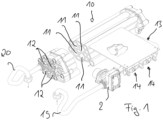
- the instantaneous water heater according to the invention is shown schematically.
- the instantaneous water heater comprises a fluid-permeable channel arrangement 10. This comprises several heating channels 11 designed to heat a liquid.
- An electrical heating element 12 is arranged in each of the heating channels 11.
- the instantaneous water heater according to the invention also comprises control electronics 13, which in Figure 1 simplified as a printed circuit.
- the control electronics 13 are designed to control electronic power switches 14 in order to electrically operate the heating elements 12.
- the control electronics 13 are designed to control the heating power of the heating elements.
- control electronics are designed as a microprocessor control.
- the continuous flow heater further comprises a - in Figure 2 shown - flow measuring device 15, which is electrically connected to the control electronics 13 and is designed to detect the volume flow of the liquid flowing through the channel arrangement 10.
- the control electronics 13 are set up to use the flow measuring device 15 to detect the start of a dispensing process when a first minimum volume flow setting is exceeded and the end of the dispensing process when a second minimum volume flow setting is not reached.
- the control electronics 13 comprises, for example, a comparison unit 16 that compares the measured volume flow with the specified values Vmax and Vmin.
- the comparison unit 16 is set up, for example, to generate a start and a stop signal that is indicative of the start and end of a dispensing process. These signals are fed, for example, to an evaluation unit 17 that is set up to determine and provide consumption data 18 from the previous dispensing process after the end of the dispensing process.
- the flow heater shown as an example also includes a water inlet 19, which is designed to supply the liquid to be heated and is connected on the inlet side to the channel arrangement 10. The heated liquid is returned via the water outlet 20 after flowing through.
- a motor valve 21 is also shown for regulating the volume flow through the channel arrangement 10. However, the motor valve 21 is optional and not essential for the present invention.
- the control electronics 13 are preferably set up to determine the electrical energy consumed by the instantaneous water heater during the tapping process as consumption data.
- the control electronics 13 here comprises, for example, an energy determination unit which is part of the evaluation unit 17.
- control electronics 13 are designed to calculate the electrical energy consumed based on the control of the electronic power switches 14.
- the control electronics 13 comprises a control and regulating unit 22, which is connected to the evaluation unit 17 in a signal-conducting manner.
- the control electronics 13 are advantageously set up to calculate the electrical energy consumed by counting the half-waves switched by the power switches 14.
- the heating power of the heating elements 13 is controlled, for example, by the control and regulating unit 22. This passes the number of half-waves during which the respective heating elements 13 are switched on to the evaluation unit 17.
- the evaluation unit 17 determines the electrical energy consumed by calculation on the basis of these control data.
- the control electronics 13 also preferably comprise power measuring means (not shown in detail in the drawing) for measuring the instantaneous power of the electrical power consumed by the at least one heating element 12.
- the control electronics 13 are also designed to determine the electrical energy consumed during the tapping process by integrating the instantaneous power over the duration of the tapping process.
- control electronics 13 each comprise at least one voltage measuring unit and at least one current measuring unit. These are each designed and set up to measure the effective values of the heating current and heating voltage. The said effective value measurement of voltage and current forms the basis for the precise determination of the energy actually consumed. The control electronics 13 are therefore set up to determine the electrical energy consumed by the at least one heating element 13 on the basis of the measured heating current and the heating voltage over the duration of the tapping process.
- the instantaneous water heater according to the invention preferably comprises first and second temperature sensors (not shown in the drawing).
- the first temperature sensor is designed to measure the inlet water temperature
- the second temperature sensor is designed to measure the water outlet temperature.
- the control electronics 13 are designed to calculate the amount of heat required to heat the water on the basis of the temperature difference between the outlet water temperature measured by means of the second temperature sensor and the inlet water temperature measured by means of the first temperature sensor as well as a water volume flow measured by means of the flow measuring device.
- control electronics 13 are set up on the basis of the determined heat quantity taking into account at least one efficiency-relevant device parameter to determine the electrical energy consumed by the at least one heating element during the tapping process.
- the device parameters are preset in the control electronics 13 and take into account, for example, the overall efficiency of the instantaneous water heater, heat losses or the like.
- control electronics 13 are configured to determine the amount of water flowing through the channel arrangement during the tapping process as consumption data by means of the flow measuring device 15.
- control electronics 13 are configured to determine the costs of the tapping process as consumption data based on the electrical energy consumed and/or the amount of water flowing through the channel arrangement 10.
- control electronics 13 further comprises a display device 23, which is designed to automatically display the consumption data determined after the end of the dispensing process, at least temporarily.
- the consumption data is thus automatically displayed to the user after a dispensing process.
- the display duration is preferably a few seconds, so that the user can read and take note of the consumption data without rushing.
- the invention also relates to the method mentioned at the outset.
- the above statements regarding the device according to the invention also apply analogously to the method according to the invention, so that in order to avoid repetition, reference is also made to the previous statements in connection with the method according to the invention.
- the flow measuring device 15 detects the start of a tapping process when a first minimum volume flow specification is exceeded and the end of the tapping process when a second minimum volume flow specification is not reached. After the end of the tapping process, the consumption data 18 of the previous tapping process are determined and provided. Preferably, the electrical energy consumed by the instantaneous water heater during the tapping process is determined as consumption data.
- the electrical energy consumed is determined on the basis of the control of the electronic circuit breakers 14 with the control electronics 13.
- the electrical energy consumed is calculated by counting the half-waves switched by the circuit breakers 14.
- the instantaneous power of the electrical power consumed by the at least one heating element 12 is measured by means of a power measuring device set up for this purpose and the electrical energy consumed during the tapping process is calculated by integrating the instantaneous power over the duration of the tapping process.
- the effective values of heating current and heating voltage are measured by means of at least one voltage measuring unit and at least one current measuring unit and, on the basis of these measurements, the electrical energy absorbed by the at least one heating element 12 over the duration of the tapping process is determined by means of the control electronics 13.
- the inlet water temperature is measured by means of a first temperature sensor arranged in the channel arrangement 10 on the water inlet side and the outlet water temperature is measured by means of a second temperature sensor arranged in the channel arrangement on the water outlet side, and the electrical energy consumed is determined by determining a temperature difference between the outlet water temperature and the inlet water temperature by the control electronics 13.
- the method is preferably characterized by determining the amount of water flowing through the channel arrangement 10 during the tapping process as consumption data 18.
- the consumption data 18 optionally include the costs of the tapping process, which are determined as the consumption data based on the electrical energy consumed and/or the amount of water flowing through the channel arrangement, knowing the respective costs for electricity and water.
- the determined consumption data are temporarily displayed automatically after the end of the dispensing process by means of a display device 23.
Landscapes
- Engineering & Computer Science (AREA)
- Physics & Mathematics (AREA)
- Chemical & Material Sciences (AREA)
- Combustion & Propulsion (AREA)
- Thermal Sciences (AREA)
- Mechanical Engineering (AREA)
- General Engineering & Computer Science (AREA)
- General Physics & Mathematics (AREA)
- Fluid Mechanics (AREA)
- Computer Hardware Design (AREA)
- Human Computer Interaction (AREA)
- Heat-Pump Type And Storage Water Heaters (AREA)
Priority Applications (1)
| Application Number | Priority Date | Filing Date | Title |
|---|---|---|---|
| EP23161475.1A EP4431822A1 (fr) | 2023-03-13 | 2023-03-13 | Chauffe-eau instantané et procédé de chauffage d'un liquide |
Applications Claiming Priority (1)
| Application Number | Priority Date | Filing Date | Title |
|---|---|---|---|
| EP23161475.1A EP4431822A1 (fr) | 2023-03-13 | 2023-03-13 | Chauffe-eau instantané et procédé de chauffage d'un liquide |
Publications (1)
| Publication Number | Publication Date |
|---|---|
| EP4431822A1 true EP4431822A1 (fr) | 2024-09-18 |
Family
ID=85601471
Family Applications (1)
| Application Number | Title | Priority Date | Filing Date |
|---|---|---|---|
| EP23161475.1A Pending EP4431822A1 (fr) | 2023-03-13 | 2023-03-13 | Chauffe-eau instantané et procédé de chauffage d'un liquide |
Country Status (1)
| Country | Link |
|---|---|
| EP (1) | EP4431822A1 (fr) |
Citations (4)
| Publication number | Priority date | Publication date | Assignee | Title |
|---|---|---|---|---|
| DE3842857A1 (de) * | 1988-12-20 | 1990-06-21 | Stiebel Eltron Gmbh & Co Kg | Elektrischer durchlauferhitzer |
| US6806446B1 (en) * | 2002-10-04 | 2004-10-19 | Stephen D. Neale | Power management controls for electric appliances |
| US8297525B1 (en) * | 2008-07-22 | 2012-10-30 | Niagara Industries, Inc. | Digital control system for tankless water heater assembly |
| US20200025418A1 (en) * | 2018-07-20 | 2020-01-23 | Stiebel Eltron Gmbh & Co. Kg | Procedure for Displaying Performance Data on the Front of a Tankless Electric Water Heater |
-
2023
- 2023-03-13 EP EP23161475.1A patent/EP4431822A1/fr active Pending
Patent Citations (4)
| Publication number | Priority date | Publication date | Assignee | Title |
|---|---|---|---|---|
| DE3842857A1 (de) * | 1988-12-20 | 1990-06-21 | Stiebel Eltron Gmbh & Co Kg | Elektrischer durchlauferhitzer |
| US6806446B1 (en) * | 2002-10-04 | 2004-10-19 | Stephen D. Neale | Power management controls for electric appliances |
| US8297525B1 (en) * | 2008-07-22 | 2012-10-30 | Niagara Industries, Inc. | Digital control system for tankless water heater assembly |
| US20200025418A1 (en) * | 2018-07-20 | 2020-01-23 | Stiebel Eltron Gmbh & Co. Kg | Procedure for Displaying Performance Data on the Front of a Tankless Electric Water Heater |
Similar Documents
| Publication | Publication Date | Title |
|---|---|---|
| DE69231869T2 (de) | Verfahren und Gerät zur Prüfung elektronischer Elektrizitätszähler | |
| DE69811353T2 (de) | Erhitzungsgefäss und verfahren zum regulieren des erhitzungselementes eines solchen gefässes. | |
| EP2696175B1 (fr) | Procédé de détection du débit d'une pompe à centrifuge | |
| EP2468155B1 (fr) | Procédé de réglage de la préparation d'eau chaude | |
| DE102005017617A1 (de) | Verfahren zur Temperatursteuerung und Temperatursteuereinheit eines Ofens | |
| DE102016104225A1 (de) | Heizkostenverteiler und Verfahren zur Erfassung der durch einen Heizkörper abgegebenen Wärmemenge | |
| WO2012046165A2 (fr) | Système pour appareils ménagers | |
| DE102010012868A1 (de) | Vorrichtung zum Ausbringen eines Mediums mit einer einstellbaren Temperatur | |
| DE69409999T2 (de) | Elektrodenkessel mit automatischer Steuerung | |
| CH621196A5 (fr) | ||
| DE3243198A1 (de) | Verfahren zur ermittlung des waermeverbrauchs von heizkoerpern und vorrichtung zur durchfuehrung des verfahrens zum zwecke der heizkostenverteilung | |
| DE2803155B1 (de) | Messeinrichtung zur Ermittlung des Effektivwertes der Leistung eines Energieverbrauchers ueber eine Berechnungsperiode | |
| EP4431822A1 (fr) | Chauffe-eau instantané et procédé de chauffage d'un liquide | |
| EP0229323B1 (fr) | Chauffe-eau instantané | |
| DE102011113541A1 (de) | Messvorrichtung für Wasserzähler und Verfahren zum Betreiben einer batteriebetriebenen Messvorrichtung | |
| EP3907578B1 (fr) | Procédé de détermination du débit de soutirage sur un dispositif accumulateur d'eau chaude | |
| EP0470935A1 (fr) | Méthode pour mesurer la quantité de chaleur et installation de chauffage utilisant cette méthode | |
| DE102019004961B4 (de) | Verfahren zur Anzeige von Leistungsdaten auf der Stirnseite eines elektrischen Durchlauferhitzers | |
| DE102005007914A1 (de) | Verfahren und Einrichtung zur Verbrauchskostenerfassung bei raumlufttechnischen Anlagen | |
| EP2102617A1 (fr) | Procédé et dispositif pour mesurer la température d'exploitation d'un moteur de commande | |
| DE102009055670A1 (de) | Verfahren zur Analyse der Wärmemengenverteilung in einem Heizsystem und Vorrichtung zur Durchführung des Verfahrens | |
| DE2019020A1 (de) | Verfahren zur Beeinflussung des Leistungsbezugs eines Verbrauchers in einer Meßperiode | |
| DE102008011117A1 (de) | Vorrichtung zur Erkennung von Luftblasen in einer fluiddurchströmten Heizeinrichtung sowie ein Verfahren für eine solche Vorrichtung | |
| EP4083520A1 (fr) | Procédé de fonctionnement d'une installation technique thermique | |
| DE4344243A1 (de) | Elektrischer Durchlauferhitzer und Verfahren für einen elektrischen Durchlauferhitzer |
Legal Events
| Date | Code | Title | Description |
|---|---|---|---|
| PUAI | Public reference made under article 153(3) epc to a published international application that has entered the european phase |
Free format text: ORIGINAL CODE: 0009012 |
|
| STAA | Information on the status of an ep patent application or granted ep patent |
Free format text: STATUS: THE APPLICATION HAS BEEN PUBLISHED |
|
| AK | Designated contracting states |
Kind code of ref document: A1 Designated state(s): AL AT BE BG CH CY CZ DE DK EE ES FI FR GB GR HR HU IE IS IT LI LT LU LV MC ME MK MT NL NO PL PT RO RS SE SI SK SM TR |
|
| STAA | Information on the status of an ep patent application or granted ep patent |
Free format text: STATUS: REQUEST FOR EXAMINATION WAS MADE |
|
| 17P | Request for examination filed |
Effective date: 20250314 |