EP4431901A1 - Zugrohrdruckentlastungstestvorrichtung - Google Patents
Zugrohrdruckentlastungstestvorrichtung Download PDFInfo
- Publication number
- EP4431901A1 EP4431901A1 EP22889062.0A EP22889062A EP4431901A1 EP 4431901 A1 EP4431901 A1 EP 4431901A1 EP 22889062 A EP22889062 A EP 22889062A EP 4431901 A1 EP4431901 A1 EP 4431901A1
- Authority
- EP
- European Patent Office
- Prior art keywords
- pipe
- train
- pressure relief
- test device
- test
- Prior art date
- Legal status (The legal status is an assumption and is not a legal conclusion. Google has not performed a legal analysis and makes no representation as to the accuracy of the status listed.)
- Pending
Links
Images

Classifications
-
- G—PHYSICS
- G01—MEASURING; TESTING
- G01M—TESTING STATIC OR DYNAMIC BALANCE OF MACHINES OR STRUCTURES; TESTING OF STRUCTURES OR APPARATUS, NOT OTHERWISE PROVIDED FOR
- G01M13/00—Testing of machine parts
-
- B—PERFORMING OPERATIONS; TRANSPORTING
- B60—VEHICLES IN GENERAL
- B60T—VEHICLE BRAKE CONTROL SYSTEMS OR PARTS THEREOF; BRAKE CONTROL SYSTEMS OR PARTS THEREOF, IN GENERAL; ARRANGEMENT OF BRAKING ELEMENTS ON VEHICLES IN GENERAL; PORTABLE DEVICES FOR PREVENTING UNWANTED MOVEMENT OF VEHICLES; VEHICLE MODIFICATIONS TO FACILITATE COOLING OF BRAKES
- B60T17/00—Component parts, details, or accessories of power brake systems not covered by groups B60T8/00, B60T13/00 or B60T15/00, or presenting other characteristic features
- B60T17/18—Safety devices; Monitoring
- B60T17/22—Devices for monitoring or checking brake systems; Signal devices
- B60T17/228—Devices for monitoring or checking brake systems; Signal devices for railway vehicles
-
- G—PHYSICS
- G01—MEASURING; TESTING
- G01L—MEASURING FORCE, STRESS, TORQUE, WORK, MECHANICAL POWER, MECHANICAL EFFICIENCY, OR FLUID PRESSURE
- G01L5/00—Apparatus for, or methods of, measuring force, work, mechanical power, or torque, specially adapted for specific purposes
- G01L5/28—Apparatus for, or methods of, measuring force, work, mechanical power, or torque, specially adapted for specific purposes for testing brakes
-
- G—PHYSICS
- G01—MEASURING; TESTING
- G01M—TESTING STATIC OR DYNAMIC BALANCE OF MACHINES OR STRUCTURES; TESTING OF STRUCTURES OR APPARATUS, NOT OTHERWISE PROVIDED FOR
- G01M17/00—Testing of vehicles
- G01M17/08—Railway vehicles
Definitions
- the present disclosure relates to a pressure relief test device, in particular to a pressure relief test device for a train pipe, and further relates to a pressure relief test device for a train pipe of a heavy-haul combined train.
- a heavy-haul combined train is a main transportation tool for railway freight, and its braking instructions are mainly transmitted through a train pipe filled with compressed air.
- a rate of pressure decrease of the train pipe directly affects a braking effect of the train. Therefore, a test device is required to simulate the generation of the braking instructions after the compressed air is released due to leakage or even a broken coupler in the train pipe of the heavy-haul combined train.
- test devices in the related art cannot accurately simulate the damage or breakage of the train pipe, nor avoid making any changes to the locomotives and vehicles. They cannot achieve detachment and attachment of the test devices at any time.
- the structures of the test devices are complex, and are inconvenient to use and maintain.
- a pressure relief test device for a train pipe, which is applied to a train and includes: a connecting pipe, a test pipe, and a cut-out cock.
- Pipe joints are provided at two ends of the connecting pipe for sealing connection to the train.
- the test pipe is sealingly connected to the connecting pipe.
- the cut-out cock is provided on the test pipe.
- the connecting pipe includes a first connecting pipe and a second connecting pipe, wherein a three-way pipe connector is sealingly provided between the first connecting pipe and the second connecting pipe, with a third port of the three-way pipe connector being sealingly connected to the test pipe.
- the first connecting pipe and the second connecting pipe include a plurality of pipe segments, wherein a pipe joint is provided between every two pipe segments.
- the pipe joint is made of a material resistant to low temperature, corrosion and rust.
- the connecting pipe is made of a material resistant to low temperature, corrosion and rust.
- the connecting pipe is a hose.
- the connecting pipe is a rubber hose or a metal hose.
- the test pipe is a rigid pipe.
- the test pipe is a seamless stainless steel pipe or a carbon steel pipe.
- the test pipe is a rubber hose or a metal hose.
- the pressure relief test device for the train pipe proposed in this disclosure includes a connecting pipe, a test pipe and a cut-out cock, wherein the connecting pipe is provided with pipe joints at two ends for sealing connection to a train, the test pipe is sealingly connected to the connecting pipe; and the cut-out cock is provided on the test pipe.
- the pressure relief test device for the train pipe proposed can accurately simulate the pressure relief situation of compressed air in the train pipe after the train pipe of any intermediate vehicle of a heavy-haul combined train is damaged or broken, making the test data more accurate.
- the device has a simple structure and can be directly connected without making any modifications to the locomotives and vehicles. It can be detached and attached at any time and is convenient for use and maintenance.
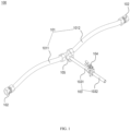
- 100 pressure relief test device for train pipe. 101, connecting pipe. 102, pipe joint. 103, test pipe. 104, cut-out cock. 105, three-way pipe connector. 1011, first connecting pipe. 1012, second connecting pipe. 1031, first test pipe. 1032, second test pipe. 301, locomotive. 302, vehicle. 303, train pipe.
- a three-way pipe connector 105 is sealingly provided between the first connecting pipe 1011 and the second connecting pipe 1012, with a third port of the three-way pipe connector 105 being sealingly connected to the test pipe 103.
- the test pipe 103 includes a first test pipe 1031 and a second test pipe 1032.
- the pressure relief test device for the train pipe proposed in this disclosure is illustrated using the application to a heavy-haul combined train as an example. It is readily understood by those skilled in the art that a variety of modifications, additions, substitutions, deletions, or other changes to the specific embodiments described below for the purpose of applying the relevant design of this disclosure to other types of trains, would still fall within the scope of the principles of the disclosed pressure relief test device 100 for the train pipe.
- the connecting pipe 101 is made of a material that is resistant to low temperature, corrosion, and rust.
- the connecting pipe is usually a hose, preferably a rubber hose that meets the performance requirements of the TB/T60 specification. Alternatively, a qualified metal hose can also be used.
- the test pipe 103 is a rigid pipe, which may be a steel pipe, preferably a seamless stainless steel pipe or a carbon steel pipe conforming to the GB/T14976 specification.
- the test pipe 103 may also be a hose that can ensure the safety of the test, such as a rubber hose or a metal hose.
- the first connecting pipe 1011 and the second connecting pipe 1012 in the pressure relief test device 100 for the train pipe proposed in this disclosure include a plurality of pipe segments, with a pipe joint 102 being provided between every two pipe segments.
- the remaining components are the same as those of the embodiment shown in FIG. 1 .
- the number of connecting pipes depends on the length of each connecting pipe and the distance between the two train vehicles to be connected.
- the pressure relief test device for the train pipe provided in this disclosure is suitable for air pipelines with ambient temperature ranging from -50° to 70°, nominal pressure not exceeding 1000KPa, and inner diameter of pipeline greater than 25mm.
- FIG. 3 illustrates an installation position of the pressure relief test device 100 for the train pipe of this disclosure, in which a heavy-haul combined train consists of a locomotive 301 and vehicles 302. Under normal conditions, the locomotive 301 and the vehicle 302 are connected to each other through a train pipe 303, and the vehicle 302 and the vehicle 302 are connected to each other through the train pipe 303.
- the pressure relief test device 100 for the train pipe may be connected to the middle of the train pipe 303 between the locomotive 301 and the vehicle 302, or alternatively, the pressure relief test device 100 for the train pipe may be connected to the middle of the train pipe 303 between two adjacent vehicles 302.
- the figure shows connections of two pressure relief test devices 300 for the train pipe, but more devices can be connected at desired positions, and this disclosure is not limited in this regard.
- pressure relief test device 100 for the train pipe illustrated in the accompanying drawings and described in this specification are only a few examples of the many types of pressure relief test devices for train pipes that are capable of employing the principles of this disclosure. It is to be clearly understood that the principles of this disclosure are not limited to any of the details of the pressure relief test device for the train pipe or any of the components of the pressure relief test device for the train pipe illustrated in the accompanying drawings or described in this specification.
- the process of using the pressure relief test device for the train pipe proposed in this disclosure is as follows: with the cut-out cock 104 fully closed, the pressure relief test device 100 for the train pipe is installed between the locomotive 301 and the vehicle 302, or is installed between two adjacent vehicles 302, wherein the connecting pipe 101 of the pressure relief test device for the train pipe is connected to the train pipe 303 through the pipe joint 102 to achieve the installation of the pressure relief test device for the train pipe.
- the air pressure in the connecting pipe 101, the three-way pipe connector 105, and the first test pipe 1031 is the same as the air pressure in the train pipe 303, both of which are usually 600 kPa or 500 kPa, and the second test pipe 1032 is connected to the external air.
- opening the cut-out cock 104 causes the pressure in the train pipe 303 to drop. This can effectively simulate the pressure relief process in case of damage in the train pipe or broken coupler of any intermediate vehicle in a heavy-haul combined train.
- the rate of pressure drop in the train pipe can be controlled by adjusting the opening degree of the cut-out cock, and it can simulate the braking type used under different drop rates, e.g.,
- the pressure relief test device for the train pipe in this disclosure can accurately simulate the pressure relief situation of compressed air in the train pipe after the train pipe of any intermediate vehicle of a heavy-haul combined train is damaged or broken, making the test data more accurate.
- the device has a simple structure and can be directly connected without making any modifications to the locomotives and vehicles. It can be detached and attached at any time, is convenient for use and maintenance, and can be reused, effectively reducing costs.
- the pressure relief test device for the train pipe proposed in this disclosure includes a connecting pipe, a test pipe and a cut-out cock, wherein the connecting pipe is provided with pipe joints at two ends for sealing connection to a train, the test pipe is sealingly connected to the connecting pipe; and the cut-out cock is provided on the test pipe.
- the pressure relief test device for the train pipe of this disclosure can accurately simulate the pressure relief situation in case of damage or breakage of the train pipe in any intermediate vehicle of a heavy-haul combined train.
- the device has a simple structure and can be directly connected without making any modifications to the locomotives and vehicles. It can be detached and attached at any time, is convenient for use and maintenance, and can be reused, effectively reducing costs.
- the pressure relief test device for the train pipe of this disclosure can make the test data closer to the real situation, to provide better safety for the actual operation.
Landscapes
- Physics & Mathematics (AREA)
- General Physics & Mathematics (AREA)
- Engineering & Computer Science (AREA)
- Transportation (AREA)
- Mechanical Engineering (AREA)
- Investigating Strength Of Materials By Application Of Mechanical Stress (AREA)
- Examining Or Testing Airtightness (AREA)
Applications Claiming Priority (2)
| Application Number | Priority Date | Filing Date | Title |
|---|---|---|---|
| CN202111313088.9A CN114018608A (zh) | 2021-11-08 | 2021-11-08 | 列车管泄压试验装置 |
| PCT/CN2022/124452 WO2023078036A1 (zh) | 2021-11-08 | 2022-10-10 | 列车管泄压试验装置 |
Publications (2)
| Publication Number | Publication Date |
|---|---|
| EP4431901A1 true EP4431901A1 (de) | 2024-09-18 |
| EP4431901A4 EP4431901A4 (de) | 2025-10-29 |
Family
ID=80062180
Family Applications (1)
| Application Number | Title | Priority Date | Filing Date |
|---|---|---|---|
| EP22889062.0A Pending EP4431901A4 (de) | 2021-11-08 | 2022-10-10 | Zugrohrdruckentlastungstestvorrichtung |
Country Status (4)
| Country | Link |
|---|---|
| EP (1) | EP4431901A4 (de) |
| CN (1) | CN114018608A (de) |
| PL (1) | PL449427A1 (de) |
| WO (1) | WO2023078036A1 (de) |
Families Citing this family (2)
| Publication number | Priority date | Publication date | Assignee | Title |
|---|---|---|---|---|
| CN114018608A (zh) * | 2021-11-08 | 2022-02-08 | 中车大同电力机车有限公司 | 列车管泄压试验装置 |
| CN120720553B (zh) * | 2025-08-14 | 2025-10-28 | 西南石油大学 | 一种城镇燃气管网泄漏事故主动受控放散时长计算方法 |
Family Cites Families (11)
| Publication number | Priority date | Publication date | Assignee | Title |
|---|---|---|---|---|
| GB191514976A (en) | 1915-10-22 | 1916-09-21 | George Herbert Willans | Improvements in and relating to Feed Water Heating Apparatus or to Combined Feed Water Heating and Boiler Water Circulating Apparatus, for Locomotive and other Fire Tube Boilers. |
| US20070247000A1 (en) * | 2006-04-21 | 2007-10-25 | Fugiel Robert V | Portable control device for wireless communication with air brake line airflow manipulating device |
| CN103439058A (zh) * | 2013-08-27 | 2013-12-11 | 天津亚星金属压铸有限公司 | 一种水试压气缸自动密封装置 |
| CN103543021B (zh) * | 2013-10-10 | 2016-09-07 | 中车青岛四方机车车辆股份有限公司 | 便携式地铁制动系统试验装置 |
| CN205562184U (zh) * | 2016-04-27 | 2016-09-07 | 眉山中车制动科技股份有限公司 | 一种电控aar制动系统单车试验器 |
| CN108204900A (zh) * | 2016-12-20 | 2018-06-26 | 本钢板材股份有限公司 | 一种普通车辆制动性能试验装置 |
| BE1025280B1 (nl) * | 2017-10-25 | 2019-01-04 | BEVOLVE bvba | Werkwijze en inrichting voor de controle van rem-installaties van een samengesteld treinstel |
| CN208607017U (zh) * | 2018-08-20 | 2019-03-15 | 眉山中车制动科技股份有限公司 | 一种车辆制动试验器 |
| CN210774739U (zh) * | 2019-12-18 | 2020-06-16 | 郑州智辆电子科技有限公司 | 移动式列车制动试验装置 |
| CN112078558A (zh) * | 2020-09-03 | 2020-12-15 | 中车长春轨道客车股份有限公司 | 一种动车组制动缸管路泄露诊断的试验方法 |
| CN114018608A (zh) * | 2021-11-08 | 2022-02-08 | 中车大同电力机车有限公司 | 列车管泄压试验装置 |
-
2021
- 2021-11-08 CN CN202111313088.9A patent/CN114018608A/zh active Pending
-
2022
- 2022-10-10 WO PCT/CN2022/124452 patent/WO2023078036A1/zh not_active Ceased
- 2022-10-10 EP EP22889062.0A patent/EP4431901A4/de active Pending
- 2022-10-10 PL PL449427A patent/PL449427A1/pl unknown
Also Published As
| Publication number | Publication date |
|---|---|
| PL449427A1 (pl) | 2025-02-17 |
| WO2023078036A1 (zh) | 2023-05-11 |
| CN114018608A (zh) | 2022-02-08 |
| EP4431901A4 (de) | 2025-10-29 |
Similar Documents
| Publication | Publication Date | Title |
|---|---|---|
| EP4431901A1 (de) | Zugrohrdruckentlastungstestvorrichtung | |
| CN110053648A (zh) | 制动系统及轨道车辆 | |
| CN113551099A (zh) | 用于原油输送管道的泄压装置及系统 | |
| CN201190856Y (zh) | 补偿式高密封管接头 | |
| CN214471609U (zh) | 一种便携式铁路机车空气管路气密性试验装置 | |
| CN104048796A (zh) | 用于压力变送器的可独立更换的密封系统 | |
| US20160238157A1 (en) | Tap with integral ball valve | |
| RU2843879C2 (ru) | Устройство моделирования снижения давления для поездной тормозной магистрали | |
| CN102012352A (zh) | 测量浆液密度和酸碱度的装置 | |
| CN205424186U (zh) | 一种导管紧固连接卡箍 | |
| CN201524372U (zh) | 一种具有柔性连接的顶压装置 | |
| CN212156088U (zh) | 一种应用于高强度压力管道结构 | |
| CN201269883Y (zh) | 一种烟气排放中流速的测量装置 | |
| CN203375037U (zh) | 一种法兰垫片 | |
| CN208169793U (zh) | 一种油气管道绝缘接头应力保护系统 | |
| CN202302265U (zh) | 一种压力预警阀门 | |
| CN101776503A (zh) | 一种仪表导压管防凝装置 | |
| CN212430149U (zh) | 用于原油输送管道的泄压装置及系统 | |
| CN213018329U (zh) | 一种气动式管道封闭执行器 | |
| CN208222070U (zh) | Lng压力液位测量装置 | |
| CN210802743U (zh) | 导管弯曲应力组合应变片 | |
| BRPI0603194A (pt) | sistema para transmitir pressões entre uma parte destacável e uma parte fixa de um modelo em escala colocado em túnel aerodinámico | |
| CN203463948U (zh) | 用于城铁车辆压缩空气输送的安全保障系统 | |
| CN208398974U (zh) | 一种用于准确测量高量程液位的磁浮子浮筒液位测量系统 | |
| CN219866790U (zh) | 一种消除管路安装偏移的球头工装 |
Legal Events
| Date | Code | Title | Description |
|---|---|---|---|
| STAA | Information on the status of an ep patent application or granted ep patent |
Free format text: STATUS: THE INTERNATIONAL PUBLICATION HAS BEEN MADE |
|
| PUAI | Public reference made under article 153(3) epc to a published international application that has entered the european phase |
Free format text: ORIGINAL CODE: 0009012 |
|
| STAA | Information on the status of an ep patent application or granted ep patent |
Free format text: STATUS: REQUEST FOR EXAMINATION WAS MADE |
|
| 17P | Request for examination filed |
Effective date: 20240527 |
|
| AK | Designated contracting states |
Kind code of ref document: A1 Designated state(s): AL AT BE BG CH CY CZ DE DK EE ES FI FR GB GR HR HU IE IS IT LI LT LU LV MC ME MK MT NL NO PL PT RO RS SE SI SK SM TR |
|
| DAV | Request for validation of the european patent (deleted) | ||
| DAX | Request for extension of the european patent (deleted) | ||
| A4 | Supplementary search report drawn up and despatched |
Effective date: 20250925 |
|
| RIC1 | Information provided on ipc code assigned before grant |
Ipc: G01M 17/08 20060101AFI20250919BHEP Ipc: B60T 17/22 20060101ALI20250919BHEP Ipc: G01L 5/28 20060101ALI20250919BHEP |