EP4431969A1 - Procédé d'étalonnage d'une méthode de détection de mouvement, bobine locale, appareil de résonance magnétique et produit de programme informatique - Google Patents
Procédé d'étalonnage d'une méthode de détection de mouvement, bobine locale, appareil de résonance magnétique et produit de programme informatique Download PDFInfo
- Publication number
- EP4431969A1 EP4431969A1 EP23162376.0A EP23162376A EP4431969A1 EP 4431969 A1 EP4431969 A1 EP 4431969A1 EP 23162376 A EP23162376 A EP 23162376A EP 4431969 A1 EP4431969 A1 EP 4431969A1
- Authority
- EP
- European Patent Office
- Prior art keywords
- movement
- movement data
- magnetic resonance
- bdm
- data
- Prior art date
- Legal status (The legal status is an assumption and is not a legal conclusion. Google has not performed a legal analysis and makes no representation as to the accuracy of the status listed.)
- Pending
Links
- 230000033001 locomotion Effects 0.000 title claims abstract description 296
- 238000000034 method Methods 0.000 title claims abstract description 50
- 238000001514 detection method Methods 0.000 title claims abstract description 33
- 238000004590 computer program Methods 0.000 title claims abstract description 11
- 238000005259 measurement Methods 0.000 claims abstract description 12
- 230000001133 acceleration Effects 0.000 claims description 25
- 238000004422 calculation algorithm Methods 0.000 claims description 17
- 238000011835 investigation Methods 0.000 claims description 11
- 230000003993 interaction Effects 0.000 claims description 7
- 230000000241 respiratory effect Effects 0.000 claims description 5
- 210000000481 breast Anatomy 0.000 claims description 4
- 230000010399 physical interaction Effects 0.000 claims description 4
- 230000015654 memory Effects 0.000 claims description 3
- 239000011159 matrix material Substances 0.000 description 15
- 238000012549 training Methods 0.000 description 11
- 238000012880 independent component analysis Methods 0.000 description 8
- 210000000038 chest Anatomy 0.000 description 7
- 230000029058 respiratory gaseous exchange Effects 0.000 description 7
- 206010011224 Cough Diseases 0.000 description 4
- 230000000875 corresponding effect Effects 0.000 description 4
- 239000000203 mixture Substances 0.000 description 4
- 230000036961 partial effect Effects 0.000 description 4
- 230000000747 cardiac effect Effects 0.000 description 3
- 238000011156 evaluation Methods 0.000 description 3
- 230000005284 excitation Effects 0.000 description 3
- 238000003384 imaging method Methods 0.000 description 3
- 230000003068 static effect Effects 0.000 description 3
- 238000013519 translation Methods 0.000 description 3
- 208000012661 Dyskinesia Diseases 0.000 description 2
- 208000015592 Involuntary movements Diseases 0.000 description 2
- 210000001015 abdomen Anatomy 0.000 description 2
- 230000005540 biological transmission Effects 0.000 description 2
- 230000001276 controlling effect Effects 0.000 description 2
- 238000005516 engineering process Methods 0.000 description 2
- 230000006870 function Effects 0.000 description 2
- 230000007274 generation of a signal involved in cell-cell signaling Effects 0.000 description 2
- 230000017311 musculoskeletal movement, spinal reflex action Effects 0.000 description 2
- 238000000513 principal component analysis Methods 0.000 description 2
- 230000008569 process Effects 0.000 description 2
- 230000005355 Hall effect Effects 0.000 description 1
- 210000004204 blood vessel Anatomy 0.000 description 1
- 238000004364 calculation method Methods 0.000 description 1
- 239000000969 carrier Substances 0.000 description 1
- 230000008859 change Effects 0.000 description 1
- 230000001010 compromised effect Effects 0.000 description 1
- 230000008602 contraction Effects 0.000 description 1
- 238000012937 correction Methods 0.000 description 1
- 230000002596 correlated effect Effects 0.000 description 1
- 230000001419 dependent effect Effects 0.000 description 1
- 238000013461 design Methods 0.000 description 1
- 230000005484 gravity Effects 0.000 description 1
- 230000004886 head movement Effects 0.000 description 1
- 230000002045 lasting effect Effects 0.000 description 1
- 230000004807 localization Effects 0.000 description 1
- 210000004072 lung Anatomy 0.000 description 1
- 238000002595 magnetic resonance imaging Methods 0.000 description 1
- 210000004165 myocardium Anatomy 0.000 description 1
- 230000010355 oscillation Effects 0.000 description 1
- 239000000523 sample Substances 0.000 description 1
- 230000035945 sensitivity Effects 0.000 description 1
- 238000000926 separation method Methods 0.000 description 1
- 210000004872 soft tissue Anatomy 0.000 description 1
- 230000036962 time dependent Effects 0.000 description 1
- 210000001519 tissue Anatomy 0.000 description 1
- 230000021542 voluntary musculoskeletal movement Effects 0.000 description 1
- 230000003936 working memory Effects 0.000 description 1
Images

Classifications
-
- G—PHYSICS
- G01—MEASURING; TESTING
- G01R—MEASURING ELECTRIC VARIABLES; MEASURING MAGNETIC VARIABLES
- G01R33/00—Arrangements or instruments for measuring magnetic variables
- G01R33/20—Arrangements or instruments for measuring magnetic variables involving magnetic resonance
- G01R33/44—Arrangements or instruments for measuring magnetic variables involving magnetic resonance using nuclear magnetic resonance [NMR]
- G01R33/48—NMR imaging systems
- G01R33/54—Signal processing systems, e.g. using pulse sequences ; Generation or control of pulse sequences; Operator console
- G01R33/56—Image enhancement or correction, e.g. subtraction or averaging techniques, e.g. improvement of signal-to-noise ratio and resolution
-
- G—PHYSICS
- G01—MEASURING; TESTING
- G01R—MEASURING ELECTRIC VARIABLES; MEASURING MAGNETIC VARIABLES
- G01R33/00—Arrangements or instruments for measuring magnetic variables
- G01R33/20—Arrangements or instruments for measuring magnetic variables involving magnetic resonance
- G01R33/28—Details of apparatus provided for in groups G01R33/44 - G01R33/64
- G01R33/32—Excitation or detection systems, e.g. using radio frequency signals
- G01R33/34—Constructional details, e.g. resonators, specially adapted to MR
-
- G—PHYSICS
- G01—MEASURING; TESTING
- G01R—MEASURING ELECTRIC VARIABLES; MEASURING MAGNETIC VARIABLES
- G01R33/00—Arrangements or instruments for measuring magnetic variables
- G01R33/20—Arrangements or instruments for measuring magnetic variables involving magnetic resonance
- G01R33/44—Arrangements or instruments for measuring magnetic variables involving magnetic resonance using nuclear magnetic resonance [NMR]
- G01R33/48—NMR imaging systems
- G01R33/54—Signal processing systems, e.g. using pulse sequences ; Generation or control of pulse sequences; Operator console
- G01R33/56—Image enhancement or correction, e.g. subtraction or averaging techniques, e.g. improvement of signal-to-noise ratio and resolution
- G01R33/563—Image enhancement or correction, e.g. subtraction or averaging techniques, e.g. improvement of signal-to-noise ratio and resolution of moving material, e.g. flow contrast angiography
-
- G—PHYSICS
- G01—MEASURING; TESTING
- G01R—MEASURING ELECTRIC VARIABLES; MEASURING MAGNETIC VARIABLES
- G01R33/00—Arrangements or instruments for measuring magnetic variables
- G01R33/20—Arrangements or instruments for measuring magnetic variables involving magnetic resonance
- G01R33/44—Arrangements or instruments for measuring magnetic variables involving magnetic resonance using nuclear magnetic resonance [NMR]
- G01R33/48—NMR imaging systems
- G01R33/54—Signal processing systems, e.g. using pulse sequences ; Generation or control of pulse sequences; Operator console
- G01R33/56—Image enhancement or correction, e.g. subtraction or averaging techniques, e.g. improvement of signal-to-noise ratio and resolution
- G01R33/565—Correction of image distortions, e.g. due to magnetic field inhomogeneities
- G01R33/56509—Correction of image distortions, e.g. due to magnetic field inhomogeneities due to motion, displacement or flow, e.g. gradient moment nulling
-
- G—PHYSICS
- G01—MEASURING; TESTING
- G01R—MEASURING ELECTRIC VARIABLES; MEASURING MAGNETIC VARIABLES
- G01R33/00—Arrangements or instruments for measuring magnetic variables
- G01R33/20—Arrangements or instruments for measuring magnetic variables involving magnetic resonance
- G01R33/44—Arrangements or instruments for measuring magnetic variables involving magnetic resonance using nuclear magnetic resonance [NMR]
- G01R33/48—NMR imaging systems
- G01R33/58—Calibration of imaging systems, e.g. using test probes, Phantoms; Calibration objects or fiducial markers such as active or passive RF coils surrounding an MR active material
-
- G—PHYSICS
- G01—MEASURING; TESTING
- G01R—MEASURING ELECTRIC VARIABLES; MEASURING MAGNETIC VARIABLES
- G01R33/00—Arrangements or instruments for measuring magnetic variables
- G01R33/20—Arrangements or instruments for measuring magnetic variables involving magnetic resonance
- G01R33/44—Arrangements or instruments for measuring magnetic variables involving magnetic resonance using nuclear magnetic resonance [NMR]
- G01R33/48—NMR imaging systems
- G01R33/54—Signal processing systems, e.g. using pulse sequences ; Generation or control of pulse sequences; Operator console
- G01R33/56—Image enhancement or correction, e.g. subtraction or averaging techniques, e.g. improvement of signal-to-noise ratio and resolution
- G01R33/567—Image enhancement or correction, e.g. subtraction or averaging techniques, e.g. improvement of signal-to-noise ratio and resolution gated by physiological signals, i.e. synchronization of acquired MR data with periodical motion of an object of interest, e.g. monitoring or triggering system for cardiac or respiratory gating
Definitions
- the invention relates to a method for calibrating a motion detection method, a local coil, a magnetic resonance device and a computer program product.
- MR magnetic resonance
- MRI magnetic resonance imaging
- an object to be examined such as a patient
- HF high-frequency
- the transmission pulses generated in conjunction with the static magnetic field in the object to be examined excite nuclear spins, which triggers spatially encoded MR signals using gradient pulses.
- the MR signals are received by the MR device and used to reconstruct MR images.
- motion data describing a possible movement of the object under examination is preferably recorded during the MR measurement. This can be used, for example, to carry out a prospective or retrospective motion correction. Furthermore, motion data can be used to control, in particular synchronize, the MR sequence with the patient's movement.
- a PT signal is emitted using a PT generator, which is modulated by a movement of the examination object and received by an RF receiving unit of the MR device.
- the RF receiving unit advantageously has a receiving bandwidth that is large enough to simultaneously receive the MR signal and the PT signal that is not in the frequency range of the MR signal.
- the RF receiving unit can comprise a plurality of receiving elements, in particular coil elements, each of which is assigned to a receiving channel.
- the received PT signal can be represented in particular as a matrix whose matrix elements, in particular their dimensions, represent the time and/or different reception channels of the PT signal.
- the PT signals of each reception channel can contain information about different movement components, such as respiratory movement and heart movement.
- PT partial signals caused by the movement components can mix in the PT signal, in particular linearly; this mixture of the PT partial signals can be described in particular by a mixing matrix.
- this mixing matrix is not known a priori, so that it must first be calibrated.
- motion detection methods such as motion detection using MR navigators and/or a camera.
- other motion detection methods are also calibrated in order to improve motion detection, particularly with regard to its accuracy.
- the second movement data is recorded continuously and/or without significant breaks in the recording period.
- the first and second movement data are recorded in a calibration phase, in particular a learning phase.
- the calibration phase can last, for example, 10 to 20 seconds.
- the first and second movement data are recorded simultaneously and/or in parallel.
- the second movement data are stored in a random access memory (RAM) of the magnetic resonance device.
- RAM random access memory
- the at least one WBDM is preferably a different method than the BDM.
- the at least one WBDM is preferably a method independent of the BDM.
- the generation of the second movement data is based on a different physical process and/or a different interaction and/or a different principle than the generation of the first movement data.
- any measurement errors in the BDM can be detected using the WBDM.
- calibrating the BDM based on the first movement data and the second movement data includes identifying at least one disturbance period in the said acquisition period (i.e. during the acquisition of the first movement data and the second movement data) in which the movement of the examination object exhibits a disturbance, wherein the BDM is calibrated taking into account the at least one disturbance period.
- the first and/or second movement data that lie within the at least one disturbance period are taken into account in a different way during the calibration than the first and/or second movement data that lie outside the at least one disturbance period.
- identifying at least one disturbance period is carried out based on the second movement data.
- the first and second movement data are recorded in a recording period between the times t i and t f ; at time t 1 ⁇ t i a disturbance begins, at time t 2 ⁇ t f the disturbance ends.
- the BDM can then be calibrated taking into account the period from t 1 to t 2 .
- identifying the at least one disturbance period comprises identifying at least one movement deviation based on the second movement data, in particular at least one predetermined movement pattern in the second movement data.
- the second movement data can, for example, describe a movement amplitude, which describes an amplitude of the movement of the examination object.
- the at least one movement deviation can, for example, be determined by the movement amplitude exceeding a predetermined exceeds the threshold value.
- the threshold value can in particular be set relative to an average movement amplitude.
- the at least one predetermined movement pattern comprises a movement pattern that describes an irregularity, in particular a signal peak in the movement amplitude.
- the first movement data recorded in the at least one fault period are ignored when calibrating the BDM.
- the BDM is calibrated exclusively based on the first movement data recorded outside the at least one fault period.
- the first movement data recorded in at least one fault period are weighted differently than the other first movement data when calibrating the BDM.
- the at least one disturbance period is assigned a disturbance intensity that indicates a severity of the disturbance.
- the first movement data that were recorded in the at least one disturbance period are weighted according to the assigned disturbance intensity when calibrating the BDM.
- the first movement data are modified, in particular adapted and/or changed, based on the second movement data.
- the BDM is calibrated based on the modified first movement data.
- corrupted first movement data which were caused, for example, by any measurement errors, are removed from the first movement data.
- Corrupted first movement data can, for example, caused by one or more unintentional movements of the object under investigation.
- the modified first movement data are advantageously movement data that have been corrected for measurement errors.
- the calibration of the BDM can be carried out more reliably using such modified first movement data.
- modifying the first movement data includes removing the first movement data within the at least one disruption period from the first movement data.
- first movement data that were recorded in the period from t 1 to t 2 can be removed from the first movement data.
- the movement of the examination object comprises at least two movement components, in particular two movement components.
- a movement component is in particular assigned to a specific type of movement.
- Several types of movement can take place simultaneously in the body of the examination subject, e.g. heart movement, breathing movement and other voluntary or involuntary movements of the patient, e.g. turning the head, moving the hand or legs, etc.
- the calibrated BDM can in particular be used to extract at least one of the at least two movement components from movement data that are recorded, for example, in a measurement phase following the calibration phase according to the BDM.
- PT signals are recorded as the first movement data in the calibration phase.
- the examination subject in particular the patient, should breathe as normally as possible in the calibration phase.
- a demixing solution can advantageously be calculated that is suitable for separating the at least two movement components.
- One movement component of the at least two movement components can be, for example, a breathing movement, a heart movement, a head movement or a movement of the patient's entire body.
- the calculation of the demixing solution can advantageously be carried out more precisely by taking the second movement data into account.
- calibrating the BDM comprises calibrating a BSS algorithm (BSS: Blind Signal Separation) for separating the at least two movement components.
- BSS Blind Signal Separation
- the BSS algorithm comprises an ICA algorithm (ICA: Independent Component Analysis) and/or a PCA algorithm (PCA: Principal Component Analysis), in particular a cPCA algorithm (cPCA: complex Principal Component Analysis).
- ICA Independent Component Analysis
- PCA Principal Component Analysis
- cPCA complex Principal Component Analysis
- the at least two movement components include a heart movement and/or a breathing movement of the examination object.
- cardiac movement can be defined as any movement caused by a regular contraction of the heart muscle, whether in the heart itself or in other parts of the body affected by it, in particular via arterial blood vessels.
- respiratory movement can be defined as any movement caused by a regular filling or emptying of the lungs with air, whether in the chest and/or abdomen itself or in other parts of the body affected by it.
- the application of an ICA algorithm provides in particular that a demixing matrix is calculated from a calibration portion of movement data, for example a PT signal.
- the ICA algorithm can in particular be applied to several movement data, for example recorded by different reception channels.
- a demixing matrix separates signals of different types of movement in the movement data. (If a signal is to be assigned to only one type of movement extracted from the movement data, this can also be done using a demixing vector.)
- the unmixing matrix when applied to a PT signal, separates at least one specific type of motion, preferably the cardiac component, from other possible signal components.
- this unmixing matrix can be either complex or real-valued.
- the second movement data are recorded with at least one sensor, in particular a motion sensor.
- the second movement data are recorded with at least one sensor that is moved by the movement of the examination object, in particular by a movement of a breast of the examination object.
- the second movement data describe a position of the at least one sensor in relation to the magnetic resonance device, in particular to a magnetic field, in particular the main magnetic field (B0 field) and/or a gradient magnetic field of the magnetic resonance device, and/or the acceleration of the at least one sensor.
- the second movement data are recorded with at least one sensor that is arranged in or on a component of the magnetic resonance device attached to the examination object, for example a local coil, which is moved by the movement of the examination object, in particular by a movement of a breast of the examination object.
- a component of the magnetic resonance device attached to the examination object for example a local coil
- the second motion data describe a position of the local coil with respect to the magnetic resonance device, in particular with respect to the main magnetic field of the magnetic resonance device, and/or the acceleration of the local coil.
- the at least one sensor comprises a magnetic field sensor, in particular a Hall sensor, in particular a 3D Hall sensor, and/or an acceleration sensor and/or a gyro sensor.
- a magnetic field sensor in particular a Hall sensor, in particular a 3D Hall sensor, and/or an acceleration sensor and/or a gyro sensor.
- the Hall sensor generates at least part of the second movement data through a movement in the magnetic field of the magnetic resonance device.
- a Hall sensor also known as a Hall probe or Hall sensor, after Edwin Hall
- the spatial distribution of the magnetic field is advantageously inhomogeneous, but known, so that the spatial position of the Hall sensor can be determined using a strength of the magnetic field measured by the Hall sensor.
- the second movement data in particular translation data and/or rotation data, are acquired at least partially outside a tunnel of the magnetic resonance device.
- translation data e.g. x, y and/or z data
- rotation data e.g. roll, pitch and/or yaw data
- an angular velocity can also be calculated by time-dependent recording of a rotational movement using the Hall sensor.
- second movement data can be recorded by measuring a gradient magnetic field using magnetic field sensors.
- Such a measurement would advantageously be carried out within the tunnel in which the gradient magnetic field is generated.
- An acceleration sensor (also called an accelerometer, acceleration sensor, vibration sensor, oscillation sensor, accelerometer, B-meter or G-sensor) is a sensor that measures its own acceleration.
- the acceleration sensor provides preferred acceleration values in three spatial directions.
- a gyro sensor is advantageously designed to measure angular velocities.
- a gyro sensor can advantageously separate a dynamic acceleration caused by the movement of the object under investigation or the acceleration sensor and a static acceleration caused by the earth's gravity.
- the at least one sensor comprises a plurality of sensors, each of which is based on a different physical interaction for detecting the movement of the examination object.
- the plurality of sensors each provide a portion of the second movement data.
- the at least one sensor for detecting the movement of the examination object is based on a different interaction than the BDM.
- a PT method as BDM is based on an electromagnetic interaction of a PT field with conductive tissue
- a Hall sensor is used to measure a magnetic field, in particular a main magnetic field of the magnetic resonance device
- an acceleration sensor is used to measure an acceleration.
- a combination of a plurality of sensors - for example a Hall sensor, an acceleration sensor and a gyro sensor - can achieve redundancy of the sensor data.
- the magnetic field sensor in particular the Hall sensor, and the acceleration sensor are based on different physical interactions to detect the movement of the object under investigation. This allows the calibration of the BDM, in particular the identification of at least one disturbance period, to be carried out more robustly.
- the respective movement data of the different sensors can be correlated with each other to enable a more reliable evaluation of the second movement data.
- the BDM comprises an interaction of a pilot tone signal with the moving examination object.
- the BDM is a PT method.
- a PT generator is used to emit a PT signal that is modulated by a movement of the examination object and is detected by the magnetic resonance device.
- the magnetic resonance device has a reception bandwidth that is large enough to simultaneously receive an MR signal and a PT signal that is not in the frequency range of the MR signal.
- the magnetic resonance device can comprise a plurality of reception elements, in particular coil elements, each of which is assigned to a reception channel.
- the received PT signal can be represented in particular as a matrix, the matrix elements of which represent the time and/or various receiving channels of the PT signal.
- the PT signals of each receiving channel can contain information on various movement components, such as respiratory movement and heart movement.
- PT partial signals caused by the movement components can mix in the PT signal, in particular linearly; this mixture of the PT partial signals can be described in particular by a mixing matrix.
- the mixing matrix can be determined in particular by the geometry and the sensitivity of the coil elements.
- calibrating the BDM based on the first movement data and the second movement data a calibration of the mixing matrix.
- a demixing matrix is determined based on the first movement data and the second movement data.
- the at least one predetermined criterion can in particular specify that the movement of an examination object in the recording period is sufficiently regular.
- the at least one predetermined criterion can specify that the period in the recording period in which the movement of an examination object in the recording period is sufficiently regular does not exceed a predetermined threshold value.
- a threshold value can, for example, be a certain amplitude of the movement of the examination object (e.g. an absolute movement in the unit "cm") and/or a certain acceleration.
- the amplitude criterion can be used to detect a very deep breath by the patient.
- the acceleration criterion can be used to detect a cough or sneeze by the patient. Such criteria can also be combined.
- the check can ensure that the quality and/or quantity of the first movement data recorded is sufficient to (successfully) calibrate the BDM.
- a local coil with at least one sensor for detecting second movement data is proposed in order to carry out a method described above.
- a magnetic resonance device in particular with such a local coil, is proposed, which is designed to carry out a method described above.
- the advantages of the proposed local coil and the proposed magnetic resonance device essentially correspond to the advantages of the proposed method for calibrating a motion detection method, which are set out in detail above.
- Features, advantages or alternative embodiments mentioned here can also be transferred to the other claimed subject matters and vice versa.
- a computer program product which comprises a program and can be loaded directly into a memory of a programmable system control unit of a magnetic resonance device and has program means, e.g. libraries and auxiliary functions, to carry out a proposed method when the computer program product is executed in the system control unit of the magnetic resonance device.
- the computer program product can comprise software with a source code which still has to be compiled and linked or which only has to be interpreted, or an executable software code which only has to be loaded into the system control unit for execution.
- the computer program product advantageously enables the proposed method to be carried out quickly, in an identically repeatable and robust manner.
- the computer program product is preferably configured in such a way that it can carry out the proposed method steps using the system control unit.
- the system control unit has the prerequisites such as a corresponding working memory, a corresponding graphics card or a corresponding logic unit so that the respective method steps can be carried out efficiently.
- the computer program product is stored, for example, on a computer-readable medium or on a network or server, from where it can be loaded into the processor of a local system control unit, which can be directly connected to the magnetic resonance device or can be designed as part of the magnetic resonance device.
- control information of the computer program product can be stored on an electronically readable data carrier.
- the control information of the electronically readable data carrier can be designed in such a way that it carries out a proposed method when the data carrier is used in a system control unit of a magnetic resonance device.
- Examples of electronically readable data carriers are a DVD, a magnetic tape or a USB stick on which electronically readable control information, in particular software, is stored. If this control information is read from the data carrier and stored in a system control unit of the magnetic resonance device, all proposed embodiments of the method described above can advantageously be carried out.
- the magnetic resonance device 10 comprises a magnet unit 11, which has a main magnet 12 for generating a strong and in particular temporally constant main magnetic field 13, also called a B0 field.
- the magnetic resonance device 10 comprises a patient receiving area 14, in particular in the form of a tunnel, for receiving a patient 15 as an examination subject.
- the patient receiving area 14 in the present exemplary embodiment is cylindrical and is surrounded in a circumferential direction by the magnet unit 11 in a cylindrical manner. In principle, however, a different design of the patient receiving area 14 is conceivable at any time.
- the patient 15 can be pushed into the patient receiving area 14 by means of a patient support device 16 of the magnetic resonance device 10.
- the patient support device 16 has a patient table 17 designed to be movable within the patient receiving area 14.
- the magnet unit 11 further comprises a gradient coil unit 18 for generating a gradient magnetic field that is used for spatial coding during imaging.
- the gradient coil unit 18 is controlled by means of a gradient control unit 19 of the magnetic resonance device 10.
- the magnet unit 11 further comprises a high-frequency antenna unit 20, which in the present embodiment is designed as a body coil that is permanently integrated into the magnetic resonance device 10.
- the high-frequency antenna unit 20 is controlled by a high-frequency antenna control unit 21 of the magnetic resonance device 10 and radiates high-frequency excitation pulses into an examination room that is essentially formed by a patient receiving area 14 of the magnetic resonance device 10.
- the main magnetic field 13 generated by the main magnet 12 causes an excitation of atomic nuclei.
- Magnetic resonance signals are generated by relaxation of the excited atomic nuclei.
- the high-frequency antenna unit 20 is designed to receive the magnetic resonance signals, and thus represents part of an RF receiving unit of the magnetic resonance device.
- the magnetic resonance device 10, in particular as part of the high-frequency antenna unit 20, comprises a local coil 26 which is arranged on the chest of the patient 15.
- the local coil 26 can be strapped to the patient 15, for example, using belts.
- Such a local coil 26 is, for example, a body array coil with several coil elements.
- the local coil 26 is therefore a component of the magnetic resonance device attached to the patient 15, which is moved by the movement of the patient 15, in particular by a movement of a chest of the patient 15.
- the local coil 26 is designed to receive the magnetic resonance signals.
- the local coil 26 is advantageously attached near the area of the patient 15 that is to be recorded using a magnetic resonance measurement.
- the magnetic resonance signals generated in this area can thus be recorded with a particularly high signal-to-noise ratio. It is also conceivable that the local coil 26 is designed to transmit high-frequency excitation pulses.
- the magnetic resonance device 10 has a system control unit 22 for controlling the main magnet 12, the gradient control unit 19 and for controlling the radio frequency antenna control unit 21.
- the system control unit 22 controls centrally the magnetic resonance device 10, such as in particular the implementation of a magnetic resonance sequence.
- the system control unit 22 comprises an evaluation unit (not shown in detail) for evaluating the magnetic resonance signals that are acquired during the magnetic resonance examination.
- the magnetic resonance device 10 comprises a user interface 23 that is connected to the system control unit 22. Control information such as imaging parameters and reconstructed magnetic resonance images can be displayed on a display unit 24, for example on at least one monitor, of the user interface 23 for medical operators.
- the user interface 23 also has an input unit 25, by means of which information and/or parameters can be entered by the medical operators during a measurement process.
- the magnetic resonance device further comprises a pilot tone generator 29, which is arranged here in the patient table 17.
- the PT method is an electromagnetic, contactless motion detection method.
- the PT generator emits a PT signal that is modulated by a movement of the patient 15 and is recorded as first motion data by the RF receiving unit of the magnetic resonance device 10, in particular by the local coil 26.
- This motion detection method thus comprises an interaction of the PT signal with the moving patient 15.
- the PT generator 29 can be controlled, for example, by means of the system control unit 22.
- the local coil 26 advantageously has a reception bandwidth that is large enough to simultaneously receive the magnetic resonance signal and the PT signal that is not in the frequency range of the MR signal.
- the local coil 26 can comprise a plurality of reception elements, in particular coil elements, each of which is assigned to a reception channel.
- the local coil 26 comprises a magnetic field sensor in the form of a Hall sensor 27 and an acceleration sensor 28, with which second movement data can be recorded according to further movement detection methods.
- the magnetic resonance device can record further sensors for recording second movement data, such as a gyro sensor.
- the sensors 27, 28 are integrated in the local coil 26 here, for example.
- the movement of the examination object in particular the movement of the chest of the patient 15, causes the sensors 27, 28 to move together with the local coil 26.
- a mechanical connection between the sensors 27, 28 and the chest movement can be established in this way.
- the sensors 27, 28 can be used to record second movement data, which is why the sensors 27, 28 can be referred to as motion sensors.
- the Hall sensor 27 and the acceleration sensor 28 are based on different physical interactions to detect the movement of the patient 15. While the Hall sensor 27 interacts with the main magnetic field 13 and thus the signal generation is based on a magnetic force, the signal generation of the acceleration sensor 28 is based on the inertial force.
- the sensors 27, 28 are in Fig.1 arranged within the tunnel of the magnetic resonance device. However, the detection of the second movement data by the sensors 27, 28 can also take place entirely or partially outside the tunnel.
- the main magnetic field 13 is usually very homogeneous, so that the resolution of a typical Hall sensor (eg 0.1 mT) is usually not sufficient to detect typical field inhomogeneities (eg 500 nT). Therefore, translation coordinates (eg x, y, z) cannot usually be determined easily in the tunnel.
- a typical Hall sensor eg 0.1 mT
- typical field inhomogeneities eg 500 nT. Therefore, translation coordinates (eg x, y, z) cannot usually be determined easily in the tunnel.
- the local coil 26 in which the local coil 26 is wound around the patient 15
- no major translational movements of the sensors 27, 28 result from, for example, breathing and/or coughing of the patient 15; such movements are usually a maximum of a few centimeters.
- such movements usually include a rotational component in addition to the translational component, i.e.
- rotational movements such as turning, tilting and/or inclination.
- rotational movements can be determined very precisely as second movement data.
- the homogeneous main magnetic field 13 usually has only one component B0 z that is not equal to zero in the tunnel.
- the components B0 x and B0 y are usually equal to zero.
- a component of the rotational movement of the coil can therefore be calculated from the changed movement data Hall x , Hall Y , Hall Z of the Hall sensor: Hall x , Hall Y , Hall Z also change as projections of the magnetic field component B0 z in the homogeneous main magnetic field 13 of the tunnel.
- the sensors 27, 28 transmit the detected second movement data to the system control unit 22 for further evaluation.
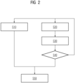
- a method for calibrating a motion detection method is presented, such as the PT method explained above.
- first motion data of the patient 15 are recorded according to the motion detection method to be calibrated.
- second motion data of the patient 15 are recorded according to at least one further motion detection method, such as by means of the Hall sensor 27 and/or the acceleration sensor 28.
- the second motion data describe in particular the position of the local coil 26 in relation to the main magnetic field 13 and its acceleration.
- the period from S10 to S20 can be considered a learning phase.
- the second movement data recorded in this learning phase are stored, for example, in a memory module, in particular a RAM, of the system control unit.
- the motion detection method to be calibrated is calibrated using the first and second motion data acquired in S10 and S20.
- at least one disturbance period that occurred during the acquisition of the first motion data and the second motion data is identified using the second motion data.
- the movement of the object under investigation exhibits a disturbance.
- the stored second movement data in S30 are analyzed to detect problematic movement patterns (e.g. sudden acceleration and position peaks due to coughing) that indicate a period of disturbance.
- problematic movement patterns e.g. sudden acceleration and position peaks due to coughing
- the second movement data can be used to check whether the movement of the patient 15 in the recording period corresponds to at least one predetermined criterion, in particular whether it is sufficiently regular. If this is the case, calibration can be carried out without further ado in S50. If this is not the case, S10, S20, S30 and S40 are carried out repeatedly.
- the motion detection method to be calibrated in particular the PT method, is then calibrated taking into account at least one disturbance period.
- the movement of the patient's 15 chest comprises two movement components, heart and breathing movement.
- the heart and breathing movement are linearly mixed by an initially unknown mixing matrix.
- a BSS algorithm in particular an ICA algorithm and/or a PCA algorithm, is preferably used, which can be calibrated using the second movement data.
- These algorithms usually require a training data set of initial movement data of approximately 10-20 seconds, during which the patient should breathe normally for 15 minutes in order to be able to determine a demixing solution that separates cardiac and respiratory movements.
- the patient 15 performs involuntary movements during this training phase, such as coughing, twisting, hiccupping, etc.
- Such disturbances in particular movement deviations, can be identified in S30 based on the second movement data and taken into account in S50.
- the quality of the first movement data can advantageously be deduced from the disturbances identified in S30. If the second movement data show a movement of the patient 15, it can be assumed that the first movement data recorded over time, in particular PT data, are not suitable for calibrating the movement detection method to be calibrated, in particular the PT method.
- the training phase should be repeated, in particular automatically. If the second movement data indicate that the first movement data is not contaminated by movement or only in a small part of the training phase, then these disturbance periods can be identified. The first movement data lying in these disturbance periods can be ignored when calibrating the motion detection method to be calibrated, so that the calibration is only carried out using the first movement data lying outside the disturbance periods (i.e. not contaminated by movement). In particular, the first movement data are modified by removing the first movement data within the disturbance periods, and the calibration in S50 is then carried out with the modified first movement data.
- the training phase does not need to be repeated, so time can be saved.
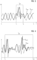
- second movement data are shown as a function of time t as an example.
- movement data D Hall recorded by the Hall sensor 27 is shown as a first part of the second movement data and movement data D accel recorded by the acceleration sensor 28 is shown as a second part of the second movement data. Based on this second movement data, it can be checked in S40 whether the training phase should be repeated.
- the second movement data shown are only in a small interval t dis of the training phase lasting from t i to t f is disturbed by unwanted movement of the patient 15, so that the first movement data lying outside of t dis (i.e. from t i to t 1 and from t 2 to t f ) are sufficient to calculate a demixing solution.
- the training phase does not need to be repeated in this case.
- the training phase should be repeated. The repetition is preferably carried out automatically so that no interaction by the operating personnel is required.
Landscapes
- Physics & Mathematics (AREA)
- Condensed Matter Physics & Semiconductors (AREA)
- General Physics & Mathematics (AREA)
- High Energy & Nuclear Physics (AREA)
- Health & Medical Sciences (AREA)
- Nuclear Medicine, Radiotherapy & Molecular Imaging (AREA)
- General Health & Medical Sciences (AREA)
- Radiology & Medical Imaging (AREA)
- Engineering & Computer Science (AREA)
- Signal Processing (AREA)
- Vascular Medicine (AREA)
- Magnetic Resonance Imaging Apparatus (AREA)
Priority Applications (3)
| Application Number | Priority Date | Filing Date | Title |
|---|---|---|---|
| EP23162376.0A EP4431969A1 (fr) | 2023-03-16 | 2023-03-16 | Procédé d'étalonnage d'une méthode de détection de mouvement, bobine locale, appareil de résonance magnétique et produit de programme informatique |
| CN202410291294.1A CN118671678A (zh) | 2023-03-16 | 2024-03-14 | 校准方法、局部线圈、磁共振装置和计算机程序产品 |
| US18/606,507 US20240310466A1 (en) | 2023-03-16 | 2024-03-15 | Method for calibrating a motion detection method, local coil, magnetic resonance apparatus and computer program product |
Applications Claiming Priority (1)
| Application Number | Priority Date | Filing Date | Title |
|---|---|---|---|
| EP23162376.0A EP4431969A1 (fr) | 2023-03-16 | 2023-03-16 | Procédé d'étalonnage d'une méthode de détection de mouvement, bobine locale, appareil de résonance magnétique et produit de programme informatique |
Publications (1)
| Publication Number | Publication Date |
|---|---|
| EP4431969A1 true EP4431969A1 (fr) | 2024-09-18 |
Family
ID=85703637
Family Applications (1)
| Application Number | Title | Priority Date | Filing Date |
|---|---|---|---|
| EP23162376.0A Pending EP4431969A1 (fr) | 2023-03-16 | 2023-03-16 | Procédé d'étalonnage d'une méthode de détection de mouvement, bobine locale, appareil de résonance magnétique et produit de programme informatique |
Country Status (3)
| Country | Link |
|---|---|
| US (1) | US20240310466A1 (fr) |
| EP (1) | EP4431969A1 (fr) |
| CN (1) | CN118671678A (fr) |
Citations (5)
| Publication number | Priority date | Publication date | Assignee | Title |
|---|---|---|---|---|
| US20100176809A1 (en) | 2009-01-09 | 2010-07-15 | Stephan Biber | Magnetic resonance tomography device with localization system and method to localize a local coil |
| US20160245888A1 (en) | 2015-02-25 | 2016-08-25 | Jan Bollenbeck | Generating motion information for an at least partially moving examination region |
| US20170160364A1 (en) | 2015-12-03 | 2017-06-08 | Matthias Fenchel | Ascertaining an item of movement information describing a movement in an at least partially moved examination region |
| EP3413076A1 (fr) | 2017-06-08 | 2018-12-12 | Siemens Healthcare GmbH | Irm impliquant la génération d'un signal de mouvement physiologique utilisant un navigateur de tonalité pilote |
| US20180353139A1 (en) | 2017-06-08 | 2018-12-13 | Siemens Healthcare Gmbh | Method for generating a medical data set of a moving body part |
-
2023
- 2023-03-16 EP EP23162376.0A patent/EP4431969A1/fr active Pending
-
2024
- 2024-03-14 CN CN202410291294.1A patent/CN118671678A/zh active Pending
- 2024-03-15 US US18/606,507 patent/US20240310466A1/en active Pending
Patent Citations (5)
| Publication number | Priority date | Publication date | Assignee | Title |
|---|---|---|---|---|
| US20100176809A1 (en) | 2009-01-09 | 2010-07-15 | Stephan Biber | Magnetic resonance tomography device with localization system and method to localize a local coil |
| US20160245888A1 (en) | 2015-02-25 | 2016-08-25 | Jan Bollenbeck | Generating motion information for an at least partially moving examination region |
| US20170160364A1 (en) | 2015-12-03 | 2017-06-08 | Matthias Fenchel | Ascertaining an item of movement information describing a movement in an at least partially moved examination region |
| EP3413076A1 (fr) | 2017-06-08 | 2018-12-12 | Siemens Healthcare GmbH | Irm impliquant la génération d'un signal de mouvement physiologique utilisant un navigateur de tonalité pilote |
| US20180353139A1 (en) | 2017-06-08 | 2018-12-13 | Siemens Healthcare Gmbh | Method for generating a medical data set of a moving body part |
Non-Patent Citations (2)
| Title |
|---|
| LUDWIG JULIANE ET AL: "Pilot tone-based motion correction for prospective respiratory compensated cardiac cine MRI", MAGNETIC RESONANCE IN MEDICINE, vol. 85, no. 5, 23 November 2020 (2020-11-23), US, pages 2403 - 2416, XP093001018, ISSN: 0740-3194, Retrieved from the Internet <URL:https://onlinelibrary.wiley.com/doi/full-xml/10.1002/mrm.28580> DOI: 10.1002/mrm.28580 * |
| MACLAREN JULIAN ET AL: "Prospective motion correction using coil-mounted cameras: Cross-calibration considerations", MAGNETIC RESONANCE IN MEDICINE, vol. 79, no. 4, 19 July 2017 (2017-07-19), US, pages 1911 - 1921, XP093071911, ISSN: 0740-3194, Retrieved from the Internet <URL:https://onlinelibrary.wiley.com/doi/full-xml/10.1002/mrm.26838> DOI: 10.1002/mrm.26838 * |
Also Published As
| Publication number | Publication date |
|---|---|
| CN118671678A (zh) | 2024-09-20 |
| US20240310466A1 (en) | 2024-09-19 |
Similar Documents
| Publication | Publication Date | Title |
|---|---|---|
| DE102013205830B4 (de) | Verfahren und Bilddatenerzeugungseinrichtung zur Erzeugung von Bilddaten eines sich bewegenden Objekts, Magnetresonanzanlage und Computerprogrammprodukt | |
| DE102007035176B4 (de) | Verfahren zur Aufzeichnung und Verarbeitung einer Folge von zeitlich aufeinander folgenden Bilddatensätzen sowie Magnet-Resonanz-Gerät | |
| DE102011007850B4 (de) | Verfahren zur getriggerten Akquisition von Messdaten mittels eines Magnetresonanzgeräts unter Unterdrückung von unerwünschten Signalen, Magnetresonanzgerät, Computerprogramm und elektronisch lesbarer Datenträger | |
| DE102013205832B4 (de) | Verfahren und Bilddatenerzeugungseinrichtung zur Erzeugung von Bilddaten eines sich bewegenden Objekts, Magnetresonanzanlage und Computerprogrammprodukt | |
| DE102010026376B4 (de) | Erstellung von hinsichtlich ihrer Erzeugungsdauer und ihrer Qualität optimierten MR-Bildern | |
| DE102012215718B4 (de) | Verfahren und Magnetresonanzanlage zur MR-Bildgebung eines vorbestimmten Volumenabschnitts eines lebenden Untersuchungsobjekts mittels Stimulieren des Untersuchungsobjekts | |
| DE102010032080B4 (de) | Getriggerte Magnetresonanzbildgebung auf der Grundlage einer partiellen parallelen Akquisition (PPA) | |
| DE102018212091A1 (de) | Ermittlung einer belastungsoptimierten MR-Sequenz | |
| DE4432570A1 (de) | Verfahren und Vorrichtung für die Kernresonanzabbildung physiologischer Funktionsinformation | |
| DE102008049709A1 (de) | Verfahren zur selektiven Darstellung einer Bewegung der Lunge, Computerprogramm, Bildverarbeitungseinheit und Magnetresonanzgerät | |
| DE102016200611A1 (de) | Lagerungsbewertung eines Untersuchungsobjekts | |
| DE102015207590A1 (de) | Verfahren zu einer Bewegungskompensation während einer Magnetresonanz-Bildgebung | |
| DE102015207591B4 (de) | Verfahren zu einer Bewegungskorrektur von Magnetresonanz-Messdaten | |
| DE102018209359A1 (de) | Bestimmung eines Merkmals charakterisierend ein beabsichtigtes Anhalten einer Atmung | |
| DE102015203932A1 (de) | Schwächungskorrektur von Emissionstomographie-Messdaten in Anwesenheit eines magnetischen Störfeldes | |
| DE102008039340B4 (de) | Verfahren zur Aufzeichnung und Darstellung von Kalibrierungsbildern sowie Magnet-Resonanz-Gerät | |
| EP3757940B1 (fr) | Détermination d'un mouvement de patient lors d'une mesure d'imagerie médicale | |
| DE102016200629A1 (de) | Verfahren zur Magnetresonanz-Bildgebung | |
| EP4431969A1 (fr) | Procédé d'étalonnage d'une méthode de détection de mouvement, bobine locale, appareil de résonance magnétique et produit de programme informatique | |
| DE102014220776B4 (de) | Verfahren zur Magnetresonanz-Bildgebung | |
| EP3553548B1 (fr) | Réglage de la séquence d'impulsions à résonance magnétique en fonction d'une prédiction du mouvement | |
| DE102017211677A1 (de) | Bewegungsabhängige Rekonstruktion von Magnetresonanzabbildungen | |
| DE102016223809B4 (de) | Verarbeitung von Bewegungssignalen während einer Magnetresonanzmessung | |
| DE102021202670A1 (de) | Verfahren zur Durchführung einer Magnetresonanzmessung eines Patienten, Magnetresonanzvorrichtung und Computerprogrammprodukt | |
| DE102014218560A1 (de) | Planung einer verzeichnungskorrigierten Magnetresonanz-Spektroskopiemessung |
Legal Events
| Date | Code | Title | Description |
|---|---|---|---|
| PUAI | Public reference made under article 153(3) epc to a published international application that has entered the european phase |
Free format text: ORIGINAL CODE: 0009012 |
|
| STAA | Information on the status of an ep patent application or granted ep patent |
Free format text: STATUS: THE APPLICATION HAS BEEN PUBLISHED |
|
| AK | Designated contracting states |
Kind code of ref document: A1 Designated state(s): AL AT BE BG CH CY CZ DE DK EE ES FI FR GB GR HR HU IE IS IT LI LT LU LV MC ME MK MT NL NO PL PT RO RS SE SI SK SM TR |
|
| STAA | Information on the status of an ep patent application or granted ep patent |
Free format text: STATUS: REQUEST FOR EXAMINATION WAS MADE |
|
| 17P | Request for examination filed |
Effective date: 20250304 |