EP4431990A2 - Élément de sortie en fibres - Google Patents
Élément de sortie en fibres Download PDFInfo
- Publication number
- EP4431990A2 EP4431990A2 EP24183678.2A EP24183678A EP4431990A2 EP 4431990 A2 EP4431990 A2 EP 4431990A2 EP 24183678 A EP24183678 A EP 24183678A EP 4431990 A2 EP4431990 A2 EP 4431990A2
- Authority
- EP
- European Patent Office
- Prior art keywords
- glass fibers
- optical element
- fiber
- cores
- optical
- Prior art date
- Legal status (The legal status is an assumption and is not a legal conclusion. Google has not performed a legal analysis and makes no representation as to the accuracy of the status listed.)
- Pending
Links
Images



Classifications
-
- G—PHYSICS
- G02—OPTICS
- G02B—OPTICAL ELEMENTS, SYSTEMS OR APPARATUS
- G02B6/00—Light guides; Structural details of arrangements comprising light guides and other optical elements, e.g. couplings
- G02B6/24—Coupling light guides
- G02B6/26—Optical coupling means
- G02B6/262—Optical details of coupling light into, or out of, or between fibre ends, e.g. special fibre end shapes or associated optical elements
-
- G—PHYSICS
- G02—OPTICS
- G02B—OPTICAL ELEMENTS, SYSTEMS OR APPARATUS
- G02B6/00—Light guides; Structural details of arrangements comprising light guides and other optical elements, e.g. couplings
- G02B6/24—Coupling light guides
- G02B6/255—Splicing of light guides, e.g. by fusion or bonding
- G02B6/2551—Splicing of light guides, e.g. by fusion or bonding using thermal methods, e.g. fusion welding by arc discharge, laser beam, plasma torch
-
- G—PHYSICS
- G02—OPTICS
- G02B—OPTICAL ELEMENTS, SYSTEMS OR APPARATUS
- G02B6/00—Light guides; Structural details of arrangements comprising light guides and other optical elements, e.g. couplings
- G02B6/24—Coupling light guides
- G02B6/255—Splicing of light guides, e.g. by fusion or bonding
- G02B6/2552—Splicing of light guides, e.g. by fusion or bonding reshaping or reforming of light guides for coupling using thermal heating, e.g. tapering, forming of a lens on light guide ends
-
- G—PHYSICS
- G02—OPTICS
- G02B—OPTICAL ELEMENTS, SYSTEMS OR APPARATUS
- G02B6/00—Light guides; Structural details of arrangements comprising light guides and other optical elements, e.g. couplings
- G02B6/24—Coupling light guides
- G02B6/26—Optical coupling means
- G02B6/32—Optical coupling means having lens focusing means positioned between opposed fibre ends
-
- G—PHYSICS
- G02—OPTICS
- G02B—OPTICAL ELEMENTS, SYSTEMS OR APPARATUS
- G02B6/00—Light guides; Structural details of arrangements comprising light guides and other optical elements, e.g. couplings
- G02B6/24—Coupling light guides
- G02B6/26—Optical coupling means
- G02B6/34—Optical coupling means utilising prism or grating
Definitions
- the present invention relates to a fiber exit element according to the preamble of patent claim 1.
- glass fibers are used in many different technical fields.
- One of the technical and particularly high-tech applications is the use of glass fibers for light transmission.
- Glass fibers are used to transmit data using light; in this case, the glass fibers can also be referred to as optical waveguides or passive glass fibers.
- Glass fibers are also used in medicine, for example for lighting and for generating images, for example in microscopes, inspection cameras and endoscopes.
- Glass fibers are also used in sensors, which can then be referred to as fiber optic sensors.
- the laser radiation can be guided as signal light radiation by means of a passive glass fiber from a laser radiation source as a signal light source or as a signal light radiation source to a processing point in order to carry out cutting or welding there, for example in material processing or in medicine.
- the laser beam can also be fed as laser radiation in this way, for example in measurement technology, microscopy or spectroscopy, for example to a sample.
- Passive glass fibers can be used to guide a laser beam, for example, in applications in mechanical engineering, telecommunications, medical technology and sensor technology.
- Fibers can also be used to generate or amplify laser light and are referred to as active glass fibers.
- Fiber lasers for generating laser light or fiber amplifiers for amplifying laser light have a doped fiber core (see below) in sections, which forms the active medium of the fiber laser or fiber amplifier, i.e. its active glass fiber.
- Common doping elements of the laser-active fiber core are neodymium, ytterbium, erbium, thulium and holmium.
- Fiber lasers or fiber amplifiers are used in industry for ultrashort pulse laser systems (for example at a wavelength of approx. 1 ⁇ m), in which Measurement technology (for example in LIDAR measurements - laser detection and ranging), in medical applications (for example at a wavelength of approx. 2 ⁇ m) or in space applications (for example at a wavelength of approx. 1.5 ⁇ m).
- Glass fibers used to amplify signal light, such as laser radiation in fiber amplifiers, or to generate laser radiation in fiber lasers usually have a fiber core made of pure glass, such as pure quartz glass, and in the case of passive glass fibers, is often doped with germanium; in the case of active glass fibers, doping is usually used as described above.
- the fiber cladding can also be doped; this applies to passive and active glass fibers.
- the fiber core can have polarization-maintaining properties for the light and can therefore be referred to as polarization-maintaining glass fibers (PM).
- They can also be photonic crystal glass fibers or hollow-core glass fibers.
- the main application area relates to glass fibers, polymer fibers or fibers made of other materials, for example so-called soft glass fibers for the mid-IR range, can also be used for such application(s).
- the fiber core is usually surrounded radially from the outside by at least one fiber cladding, which is usually closed in the circumferential direction and thus completely surrounds the fiber core, apart from the two open ends of the glass fiber.
- both passive glass fibers and active glass fibers are surrounded by a fiber coating made of polymer, for example, similar to the fiber cladding, which can then be assigned to the glass fiber.
- the fiber coating can serve to mechanically protect the glass interior of the glass fiber and influence its optical properties.
- the fiber coating primarily serves to provide mechanical protection. Glass fibers that guide light in the fiber core and in the fiber cladding (double-clad glass fibers) are usually designed with a fiber coating to fulfill mechanical and optical properties.
- Two cross-sectional shapes for the fiber cladding that are frequently used in practice are cylindrical and octagonal.
- the octagonal shape for the fiber cladding is used in particular for active glass fibers.
- Such glass fibers can be produced in long lengths and are usually available as rolls.
- the diameter of the fiber cladding usually varies between approx. 80 ⁇ m and approx. 1 mm.
- rod-type fiber is often used in practice.
- a signal light radiation input as an interface for feeding in or coupling in the signal light radiation to be amplified as input radiation from outside the fiber amplifier
- a pump light coupler which transports the pump light radiation with almost no loss from the pump light source into the cladding of the active fiber optic
- a pump light trap which absorbs non-absorbed pump light from the active fiber optic or removes it from the cladding of the fiber optic
- a signal light radiation output which shapes and/or guides the output radiation and thereby couples it out and makes it available outside the fiber amplifier.
- the signal light radiation output can also be referred to as a fiber exit element or fiber exit optics.
- a fiber laser also usually uses a pump light coupler, an active fiber optic, a pump light trap and a signal light radiation output. Since no signal light radiation is supplied from outside, but the laser radiation is generated within the fiber resonator between two reflectors or mirror elements, the signal light radiation input is omitted.
- an optical window with a one-sided anti-reflection coating for the corresponding wavelengths or a lens for collimating the output radiation can serve as a signal light radiation output or as a fiber exit element.
- the fiber exit optics can also be another glass fiber that guides the output radiation to a destination.
- Such fiber exit optics are usually connected to the open end of the glass fiber in a material-locking manner, for example by welding, also known as splicing. This allows the signal light or laser light to pass directly into the fiber exit optics, for example as an optical window or as a lens, and from there to exit to the outside, for example of the fiber amplifier or fiber laser.
- the beam of the signal light or laser light can be widened using the optical window or the lens, i.e. its cross-section can be increased and its power density can be reduced, which can be advantageous or necessary for certain applications.
- the US6,819,858 B2 describes a molded holder of non-crystalline polymer material configured to have a channel for holding a silicon chip with a plurality of adjacent V-grooves formed in an upper surface between right and left side portions thereof, a recessed area in the channel behind the chip for receiving a fiber buffer coating, and a notch formed in an upper portion of the holder between the channel and a side portion thereof for holding gain fibers of an optical fiber cable, the V-groove configured to receive individual optical fibers therein, respectively.
- Two such molded holders with silicon chips are securely stacked together with the V-grooves of the chips facing each other to hold the optical fibers therebetween.
- the disadvantage of the two previously described publications is their mechanically form-fitting and/or force-fitting hold of the individual glass fibers, which can be considered less stable, defined and/or durable than the previously described material-fitting welding or splicing.
- the mechanical forces of these connections can also generate mechanical stresses within the held glass fibers, which can affect the optical transmission behavior of the glass fibers. This can occur in an undefined manner and have a disruptive effect on the signal light transmission.
- Another disadvantage of this approach is that the free ends of the glass fibers, which form the interface between the material of the glass fiber, such as glass, and the environment, such as air, can easily be damaged or destroyed during the transmission of medium and high optical powers of several watts to several kilowatts.
- the US 2012/045169 A1 describes a method and apparatus for forming an optical fiber array assembly comprising: providing a plurality of optical fibers including a first optical fiber and a second optical fiber, providing a fiber array plate comprising a first surface and a second surface, connecting the plurality of optical fibers to the first surface of the fiber array plate, transmitting a plurality of optical signals through the optical fibers into the fiber array plate at the first surface of the fiber array plate, and emitting a composite output beam comprising light from the plurality of optical signals from the second surface of the fiber array plate.
- the plurality of optical fibers are butt welded to the first surface of the fiber array plate.
- a disadvantage of connecting the open end of at least one glass fiber to an optical element of a fiber exit optic is that both when bonding using an additional adhesive and when melting or welding the materials of the glass fiber and the optical element, material can get between the open end of the glass fiber and the entry surface of the optical element. This can lead to interference with the coupling or transmission of the signal light radiation from the core of the glass fiber into the optical element at its entry surface.
- the open end is placed bluntly on the entry surface of the optical element and is bonded together at the edges by means of an additional adhesive or by fusing or welding the materials of the glass fiber and the optical element, only a comparatively mechanically weak connection can be achieved between the open end of the glass fiber and the optical element at its entry surface.
- the alignment of the open end of the glass fiber relative to the entrance surface of the optical element can also change if the bonding or welding is uneven or if the end is placed bluntly, i.e. vertically, which can have a corresponding effect on the propagation of the signal light of the glass fiber through the optical element and can even render the manufactured component unusable.
- the entrance surface and other surfaces of the optical element outside its exit surface can be optically roughened.
- This can serve to reduce stray light radiation in the optical element, for example from the cladding of the glass fibers or reflected signal light radiation from the exit surface of the optical element, to extract it from the optical element or to reflect it diffusely.
- the reduction of such stray light radiation can be absolutely necessary, especially at higher optical powers, for the implementation of the respective application or to reduce the susceptibility of the laser system to interference. If the open end of the glass fiber is placed on an optically roughened entry surface in this way and bonded there at the edge, the transition of the signal light radiation from the core of the glass fiber into the optical element can also be impaired by the roughened surface.
- the impairments can have a significant effect, for example, on the signal transmission at the connection point, the beam quality or the polarization of the signal light radiation.
- the entire optical element as a fiber arrangement (fiber array plate) and the connected laser systems can even be destroyed. If the roughened entrance surface is omitted, the advantages of a roughened surface cannot be utilized, at least not on the entrance surface of the optical element.
- One object of the present invention is to provide a fiber exit element of the type described above which can utilize the advantages of fiber optic technology and at the same time overcome or at least reduce the disadvantages described above.
- the aim is to enable a spatially as compact arrangement of several glass fibers in the area of the fiber exit element.
- the mechanical stability of the connection between the glass fiber or glass fibers and the optical element of the fiber exit element is to be as high as possible.
- the transition of the signal light from the glass fiber to the optical element of the fiber exit element is to be as undisturbed as possible.
- the design options for several glass fibers in the area of the fiber exit element are to be increased. At least an alternative to known fiber exit elements is to be created.
- the present invention thus relates to a fiber exit element with a plurality of glass fibers, each with at least one core, which is each designed to guide a signal light radiation, which can in particular be a laser radiation.
- the fiber exit element can also be referred to as a signal light radiation output, as a fiber exit optic or as a fiber array.
- the fiber exit element further comprises at least one optical element, preferably an optical window, an optical lens, an optical beam splitter or an optical prism, which is connected to an open end of the cores of the glass fibers and is designed to To receive signal light radiation from the open ends of the cores of the glass fibers and to emit it as exit radiation to the outside via at least one exit surface.
- each of the glass fibers has at least two ends, one end of which is connected to the same optical element together with the corresponding ends of the other glass fibers, as described above.
- the open ends of the cores of the glass fibers are each arranged with a penetration depth, preferably opposite an entrance surface of the optical element, within the material of the optical element, wherein at least the material of the open ends of the cores of the glass fibers, preferably also the material of the open ends of the sheaths of the glass fibers, is fused to the material of the optical element.
- the fiber exit element is characterized in that the open ends of the cores of the glass fibers are arranged in a plane perpendicular to the longitudinal extension direction of the glass fiber.
- the open ends of at least the cores of the glass fibers and preferably also their sheaths are arranged within the material of the optical element and are bonded and held there with the material of the optical element by fusing the materials.
- the mechanical stability of the connection of the open ends of the glass fibers or their cores or their sheaths relative to the optical element can also be improved.
- the optical element also serves to shape the beam of the exit radiation or the exit beam combined from this through its shape and/or its material properties.
- the material of the optical element can be melted at least in this area by heating, so that the open ends of the glass fibers are immersed in the melted material of the optical element and the melted material of the optical element can then cool or solidify again.
- the penetration depth of the glass fibers into the material of the optical element can be selected depending on the application in such a way that the properties and advantages described above can be achieved depending on the materials and shapes of the glass fibers and the optical element.
- the penetration depth of the glass fibers into the material of the optical element can preferably be understood relative to an entry surface of the optical element, wherein the entry surface of the optical element is the outer surface of the optical element over which the glass fibers reach the optical element and penetrate its material.
- the penetration depth can also be used to influence the optical properties of the exit radiation, which can also be viewed as a combined exit beam.
- the penetration depth is dimensioned such that the open end is arranged within the material of the optical element and is laterally enclosed perpendicular to the longitudinal extension direction of the glass fibers.
- the penetration depth is preferably at least as large as the diameter of the core, preferably the cladding, of the open end of the glass fibers and/or deeper than the maximum structural depth of an optically rough or optically roughened surface.
- the optical element is connected in the region of an entry surface to at least some, preferably all, open ends of the cores of the glass fibers, preferably also to the open ends of the sheaths of the glass fibers that essentially enclose the cores, wherein the optical element is designed to widen increasingly at least in sections, preferably completely, preferably step-like or continuously, from the entry surface to the exit surface.
- the entry surface of the optical element is smaller than its exit surface, or the cross-section of the optical element increases from the entry surface to the exit surface.
- the transition from the entry surface to the exit surface can be consistently straight or step-like, for example in the form of rectangular steps or as a wave shape.
- the advantage here is that interference radiation within the optical element comes into contact more frequently with the side surface or lateral surface or with the side surfaces or lateral surfaces of the optical element, which can improve the extraction of interference radiation from the optical element.
- the entrance surface of the optical element can be made smaller and thus matched to the surface of the previously melting glass fibers, which can reduce the volume that has to be heated on the part of the optical element for melting. This can simplify the melting process, accelerate it and/or reduce the energy required for this.
- This also makes it possible to save material for the optical element and/or to keep the required installation space for the optical element to a minimum. Furthermore, this can provide options for influencing the propagation of the signal radiation within the optical element as well as the exit radiation.
- the entrance surface and the exit surface of the optical element are aligned parallel or at an angle to each other. This can influence the propagation of the signal radiation within the optical element as well as the exit radiation.
- a parallel alignment of the entrance surface and the exit surface of the optical element simplify the manufacture of the optical element and thereby reduce its costs.
- reflections of the signal light radiation from the optical element back into the glass fibers can be reduced.
- the exit radiation at the exit surface of the optical element can also be specifically deflected in this way and the length of the respective beam path can be influenced.
- At least the entrance surface of the optical element preferably all outer surfaces of the optical element except the exit surface of the optical element, are optically roughened and at least the exit surface of the optical element, preferably exactly the exit surface of the optical element, is designed with an optically smooth surface quality.
- An optically roughened surface can be achieved, for example, by processing with a mechanical tool such as grinding, but also using a laser beam as a tool.
- An optically smooth surface can also be achieved by processing with a mechanical tool such as polishing, but also using a laser beam as a tool.
- An optically smooth surface quality is given when, at the corresponding wavelength or in the corresponding wavelength range of the signal light radiation, the necessary optical properties can largely be retained when exiting via the exit surface for the respective application or a corresponding optical coating can be applied professionally.
- the scratch dig specification of the MIL-PRF-13830B standard is often used to evaluate the surface quality.
- An optically roughened surface of the optical element can be advantageous for its outer surfaces apart from the exit surface in order to allow interference radiation to exit the optical element and thereby reduce the volume of the optical element.
- Such interference light can be cladding light from the cladding of the glass fibers.
- the signal radiation can also be reflected on the side surfaces of the optical element.
- signal light radiation in the optical element can be partially reflected at the exit surface in the form of interference light.
- signal light radiation can enter the optical element again by reflection from outside, for example from the processing or application location of the signal light radiation.
- an optically roughened surface can be advantageous for reducing the aforementioned interference light radiation in the optical element and thus ensuring a safe operating state.
- the optical element preferably an entrance surface of the optical element, has at least one recess with a depth, wherein at least some, preferably all, of the open ends of the cores of the glass fibers, preferably furthermore the material of the sheaths of the glass fibers substantially enclosing the cores, are provided with the Penetration depth opposite the recess within the material of the optical element.
- the open ends of the glass fibers can be inserted deeper into the material of the optical element in this way without increasing the penetration depth.
- the depth of the recess in the entry surface of the optical element is provided so deep, for example by prior laser processing or milling, that the open ends of the glass fibers can be inserted into the material of the optical element by an additional depth of penetration, for example by melting.
- the total distance between the open ends of the glass fibers and the entry surface of the optical element is thus calculated by adding the depth of the recess and the penetration depth and can be increased accordingly easily.
- At least one exit surface of the optical element has an optical coating, preferably an optical anti-reflection coating, at least in sections, preferably over the entire surface.
- an optical anti-reflection coating can prevent or at least reduce the penetration of interfering radiation from outside the optical element.
- Such a coating can be selected accordingly in order to reflect the relevant wavelengths or wavelength ranges. This can reduce the amount of interfering radiation within the optical element.
- At least one, preferably some, particularly preferably all, of the glass fibers have at least one cladding which essentially encloses the core, wherein in the region of the fiber exit element at least one pump light trap, preferably as depressions, is formed in the material of the cladding of the glass fiber in order to conduct cladding light from the cladding of the glass fiber to the outside of the glass fiber.
- a pump light trap can also be referred to as a cladding light remover or cladding light stripper. This allows interfering cladding light to be removed from the cladding of the glass fibers immediately in front of the optical element and/or returning cladding light from the optical element to be reduced. This can reduce the entry of interfering radiation into the optical element.
- the fiber exit element has at least one tension element in the region of the fiber exit element, which is designed to exert a mechanical tension, preferably in the form of tensile forces, compressive forces, bending forces and/or shear forces, on at least the core of one, preferably some, particularly preferably all, of the glass fibers, preferably and on a jacket of the glass fiber substantially enclosing the core, over a predetermined section of the elongated extension of the glass fibers.
- a mechanical tension preferably in the form of tensile forces, compressive forces, bending forces and/or shear forces
- the area of the fiber exit element comprises at least the area, for example, within a housing of the fiber exit element as well as an area outside the housing of the fiber exit element in direct connection thereto.
- the open end of the core of at least one, preferably some, particularly preferably all, of the glass fibers is arranged at least at a first angle with respect to an entry surface of the optical element, the first angle being 90° or different from 90°, the open ends of the cores of some, preferably all, of the glass fibers preferably having the same first angle or different first angles.
- the directions of propagation of the signal radiation within the optical element can be influenced by the orientation of the open ends of the glass fibers with respect to the entry surface of the optical element.
- a vertical arrangement of the glass fibers with respect to the entry surface can simplify production.
- the propagation of the signal light radiation can be designed accordingly by angularly aligning the glass fibers with respect to the entry surface.
- the optical path that the signal radiation travels within the optical element can be increased without having to enlarge the optical element for this purpose.
- the open end of the core of at least one, preferably some, particularly preferably all, of the glass fibers is further arranged at a second angle relative to an entrance surface of the optical element, wherein the second angle is 90° or different from 90°, wherein preferably the open ends of the cores of some, preferably all, of the glass fibers have the same second angle or different second angles and/or wherein preferably the first angle and the second angle are the same or different.
- the two angles are preferably oriented perpendicular to one another. This can further increase the design options.
- At least some, preferably all, of the open ends of the cores of the glass fibers are arranged with the same penetration depth or with a different penetration depth within the material of the optical element.
- the use of the same penetration depth can simplify production.
- the exit radiation or an exit beam combined from this can be influenced in its optical properties.
- the signal light radiation of the individual glass fibers can travel optical paths of different lengths due to their different penetration depths into the optical element and thus have different optical properties at the exit surface of the optical element, such as different beam diameters.
- At least one, preferably some, particularly preferably all, of the glass fibers can be aligned around the axis of their elongated extension and are arranged in a preferred orientation.
- at least one of the glass fibers is not rotationally symmetrical but has the option, for example due to its cross section, for example as a square cross section, of being aligned differently with respect to the optical element by rotation or alignment around the axis of its elongated extension.
- This can additionally or alternatively also be the case with polarization-maintaining glass fibers and/or with glass fibers with stress cores.
- At least some, preferably all, of the open ends of the cores of the glass fibers are arranged in a linear, V-shaped, circular, semi-circular, arcuate, bundle-shaped, hollow-cylindrical or rectangular manner. This can increase the design options for the exit radiation.
- At least the open end of the core of one of the glass fibers is arranged to form a center of a circle, wherein at least some, preferably all, of the open ends of the cores of the glass fibers are arranged in a circle around the center of the circle, wherein preferably at least one radially inner circle and one radially outer circle are formed and/or wherein preferably all of the open ends of the cores of the glass fibers, preferably all of the sheaths of the glass fibers substantially enclosing the cores, are arranged at the same or different distances from one another or are arranged in contact with one another.
- the glass fiber types, shapes and diameters can vary within the fiber exit element.
- At least some, preferably all, of the open ends of the cores of the glass fibers, preferably all of the sheaths of the glass fibers that essentially enclose the cores, are arranged at the same or different distances from one another or in contact with one another. This can increase the design options for the exit radiation.
- the diameters of the glass fibers or their cladding can be reduced in a targeted manner by etching before the welding process, so that, for example, the cores of the glass fibers in the optical element can be brought closer together.
- the diameters of the individual glass fibers can also be reduced by taper, which can also lead to the geometric advantages described above.
- the mode field diameter of the signal can be modified before the welding process during taper in order to achieve the desired properties of the combined exit beam.
- a corresponding fiber exit element preferably as described above, can be manufactured to implement the corresponding and preferably the previously described properties and advantages.
- the present invention also relates to a processing device for producing a fiber exit element, preferably as described above, preferably by means of a method as described above, with at least one receiving unit for receiving a plurality of glass fibers, each with at least one core, which is designed to guide a signal light radiation, at least one receiving unit for receiving at least one optical element, which is designed to receive the signal light radiation from the open ends of the cores of the glass fibers and to emit it as exit radiation via an exit surface to the outside, and at least one first processing beam source, preferably a first laser beam source, particularly preferably a first CO2 laser beam source, which is designed to generate a first processing beam and to direct it directly or indirectly by means of a first movable alignment element, preferably by means of a first pivotable mirror, onto a processing zone of the optical element, to move it in the processing zone and to heat the processing zone of the optical element in such a way that the material of the optical element has sufficient flowability at least in the processing zone to contact the open ends of the cores of the Glass
- a processing device can be created to be able to produce fiber exit elements, preferably as described above, with the highest possible degree of machine support or automation. This can increase the quality of the manufactured products and/or reduce their costs.
- Heating or melting the processing zone of the optical element at least substantially and preferably exclusively by means of the first processing beam and accordingly heating the glass fibers or their open ends hardly or not at all by means of the first processing beam can be advantageous in that the comparatively delicate glass fibers can thereby be protected and kept as unchanged as possible in the optical element.
- the processing device has at least one second processing beam source, preferably a second laser beam source, particularly preferably a second CO2 laser beam source, which is designed to generate a second processing beam and to direct it directly or indirectly by means of a second movable alignment element, preferably by means of a second pivotable mirror, onto a processing zone of the optical element and to move it in the processing zone, so that the heating of the processing zone of the optical element can take place jointly by the first processing beam and by the second processing beam.
- a second laser beam source particularly preferably a second CO2 laser beam source
- the first processing beam source preferably and the second processing beam source
- the formation of a pump light trap can also be implemented by means of the processing device according to the invention, which can keep the manufacturing effort of the fiber exit element with pump light trap low.
- cladding light or remaining cladding light can be removed from the cladding immediately in front of the fiber exit element and thus the penetration of cladding light into the fiber exit element can be avoided, which would otherwise lead to the formation of Stray light signals within the fiber exit element. Returning cladding light coming from the optical element can also be reduced.
- the receiving unit for receiving at least the glass fibers and/or the receiving unit for receiving at least the optical element is/are arranged and/or pivotally movable in such a way that the open ends of the cores of the glass fibers can be aligned with respect to an entry surface of the optical element at least at a first angle, preferably also at a second angle, wherein the first angle, preferably and/or the second angle, is 90° or different from 90°, wherein preferably the first angle and the second angle are the same or different.
- This also allows a corresponding alignment to be carried out by the processing device.
- the processing device has at least a first image capture unit, preferably a first area camera, which is designed to optically capture the optical element received in the receiving unit from the side of the receiving unit for receiving at least the glass fibers or from the side facing away from the receiving unit for receiving at least the glass fibers, at least in the area of the processing zone.
- the processing device preferably also has a second image capture unit, preferably a second area camera, which is designed to optically capture the optical element received in the receiving unit from the side opposite the first image capture unit, at least in the area of the processing zone. This can, for example, enable a person to at least check the arrangement or alignment of the glass fibers relative to the optical element.
- the receiving unit for receiving at least the glass fibers is/are movable perpendicularly and/or rotationally to its direction of movement and/or the receiving unit for receiving at least the optical element is/are movable perpendicularly and/or rotationally to its direction of movement in such a way that the open ends of the cores of the glass fibers and the processing zone of the optical element can be aligned with one another. This also allows a corresponding alignment to be carried out by the processing device.
- the processing device preferably a control unit of the processing device, is designed to automatically align the open ends of the cores of the glass fibers and the processing zone of the optical element with each other depending on at least one optical image captured by the first image capture unit, preferably also the second image capture unit. This can enable automation of the corresponding process.
- the processing device has at least one alignment unit, preferably a gripper that can be moved in translation and rotation, which is designed to align at least one, preferably some, particularly preferably all, of the glass fibers together or independently of one another around the axis of their elongated extension relative to the optical element.
- the processing device is able to grip at least one glass fiber, for example in the area of its coating, and rotate it around its longitudinal axis by means of at least one alignment unit, so that a predetermined alignment of the glass fiber can take place.
- the alignment unit can reach individual or multiple glass fibers one after the other and align them in this way.
- the alignment unit can be moved and positioned in translation in a spatial direction and preferably in a plane perpendicular to the elongated extension direction of the glass fiber. This can be implemented, for example, by means of a corresponding gripper.
- glass fibers that are not rotationally symmetrical can be aligned differently with respect to the optical element by rotation or alignment around the axis of their elongated extension, which can allow, for example, in the case of polarization-maintaining glass fibers and/or glass fibers with stress cores, to influence the optical properties of the signal output radiation, as described above.
- the processing device has at least one temperature detection unit, preferably an infrared area camera, which is designed to detect a temperature of the optical element accommodated in the receiving unit from the side of the receiving unit for receiving at least the glass fibers at least in the region of the processing zone. This can at least enable the monitoring of the process of heating the processing zone.
- at least one temperature detection unit preferably an infrared area camera, which is designed to detect a temperature of the optical element accommodated in the receiving unit from the side of the receiving unit for receiving at least the glass fibers at least in the region of the processing zone. This can at least enable the monitoring of the process of heating the processing zone.
- the processing device preferably a control unit of the processing device, is designed to control and/or regulate the generation, preferably at least the power, and/or the positioning of at least the first processing beam, preferably also the second processing beam, depending on the temperature detected by the temperature detection unit.
- This allows the heating or melting of the processing zone to be carried out in a temperature-controlled or temperature-regulated manner. On the one hand, this can prevent unnecessary heating of the processing zone. On the other hand, this can ensure that the processing zone is sufficiently heated before the open ends of the glass fibers are moved into the processing zone. This can improve the quality of the fiber exit elements produced and/or reduce the rejection of defective fiber exit elements.
- the processing device has at least one cooling unit which is designed to cool the optical element received in the receiving unit at least substantially outside the area of the processing zone, wherein the cooling unit preferably has an air blower which is designed to direct an air flow onto the side of the optical element facing away from the receiving unit for receiving at least the glass fibers. This makes it possible to reduce the heating of the optical element outside the processing zone.
- optical glass fibers are typically used today to generate laser radiation or to transport laser radiation (beam delivery) from the laser to the site of use.
- These can be, for example, single or multi-mode glass fibers, polarization-maintaining glass fibers (PM) or photonic crystal glass fibers as well as hollow-core glass fibers - to name just a few examples of the types of glass fibers available on the market.
- the optical components according to the invention and methods for producing these components therefore relate to the full range of glass fiber types available on the market. Even if the main area of application relates to glass fibers, polymer fibers or fibers made of other materials, for example so-called soft glass fibers for the mid-IR range, can also be used for this application(s).
- glass fibers can be welded (fusion spliced) to an optical element in any arrangement (see for example Figure 1 ).
- Welding splicing
- energy radiation preferably laser radiation
- other joining techniques could also be used.
- the penetration depth of the optical glass fibers into the optical element can be adjusted depending on the application. It is also possible that the glass fibers can be connected to the optical element at different depths (z-direction of the Figure 1 ) in penetrate the optical element or individual or all glass fibers can be inserted extra deeply into the optical element through drilling or other means. In addition, individual glass fibers or all glass fibers can be inserted at a certain angle ⁇ (see for example Figure 1 ) to the optical element. This also applies to the Figure 1 not shown angle in the zy-plane.
- Laser beam sources or other beam sources can be connected to the glass fibers 1 to n. In this way, the electromagnetic radiation from several laser beam sources or other beam sources can be transported to the site of use.
- the beam sources or the power components in the optical glass fibers can be operated simultaneously, at different times, or with a temporal modulation of the individual power components in the optical glass fibers that makes sense for the process.
- the beam sources can be identical or differ, for example, in terms of polarization, wavelength, or optical pulse length. It is also possible to transfer the power or individual spectral power components of a beam source or, if applicable, laser beam source to glass fibers 1 to n in any division ratio.
- the laser or any other light source can operate continuously or in pulsed mode. Glass fibers 1 to n can also be used for a coherent or incoherent combination of laser beam sources. Depending on the application, there are numerous possible variations based on the available properties of the laser systems or other available light sources.
- the optical element can be, for example, an optical window with or without optical coating or a lens as well as an optical beam splitter, to name just a few examples of optical elements.
- the optical element can also consist of a large number of individual optical elements, for example an array of microlenses or a flexible material (for example polymer) with suitable optical properties for the respective application.
- the optical element can also consist of different materials or its material properties can be divided into its dimensions (x, y and z direction, see for example Figure 1 ), for example by partially doping the optical element. If the optical element consists of different materials, these can be glued, welded or bonded.
- the arrangement of the glass fibers on the optical element can be carried out in any way, depending on what the specific application requires. Some embodiments of arrangements of the glass fibers on the optical element are shown in the Figures 2 to 6 shown.
- the Figures 2 to 6 show, for example, that the targeted arrangement of the glass fibers on or at the optical element creates 1- or 2-dimensional fiber arrays.
- the third dimension can be used by varying the depth of the glass fibers (z-direction).
- the glass fibers can be in direct glass-to-glass contact (without spacing) or have a defined spacing.
- the spacing of the glass fibers on or at the optical element can vary from glass fiber to glass fiber - in both dimensions (x-direction and y-direction, see for example Figure 1 ).
- the diameter of the individual glass fibers can be reduced by etching the glass fibers and thus the distance between the glass fibers can be reduced.
- the glass fibers or individual glass fibers can be tapered in diameter before the welding process to/on the optical element (tapering).
- the glass fibers or individual glass fibers can be welded laterally in any arrangement (for example a fiber bundle) before the welding process to/on the optical element (fiber fusion). Manufacturing steps of tapering and welding the glass fibers as a preliminary process before the actual connection of the glass fibers with the optical element can be combined as desired.
- the glass fibers can have different diameters (typically approx. 80 ⁇ m to approx. 1.5 mm) and cross-sections, for example round, rectangular and octagonal.
- the spatial arrangement of the individual glass fibers 1 to n (see for example Figure 1 ) on/on the optical element, a defined beam shape can be achieved after the optical element (at the location of use) for a specific application, for example a line, a circle, a semicircle, a hollow cylinder or a V-shape.
- the beam shape and other properties of the radiation source can also be varied depending on various process parameters. This allows the radiation to be controlled or regulated at the place of use.
- the beam diameter of the energy beam preferably the laser beam
- the beam diameter at the place of use is very small. If radiation is emitted from the glass fibers of the first ring, the beam diameter increases. The maximum beam diameter is achieved as soon as the glass fibers from the second ring of the optical element emit radiation. This can now be used as desired in the manufacturing process, for example in laser welding or laser cutting, by means of a control or regulation.
- the temporal beam shaping or laser beam shaping could thus take place in the micro- or millisecond range.
- optical component in Figure 1 is characterized in particular by the fact that its design allows the compact combination and shaping of optical radiation with optical glass fibers for medium and higher optical powers (typically greater than approx. 1 W up to several 10 kW).
- the optical component is further characterized in particular by the fact that many glass fibers can be converted into a highly stable monolithic component in a very compact space in any shape or arrangement with the help of an optical element, for example by welding the glass fibers to the optical element, which can transport, combine and shape optical radiation with high power (up to several 10 kW) in a very small space, usually approx. 100 ⁇ m to approx. 10 mm.
- the optical component enables, as exemplified in the Figure 1 shown, a targeted radiation shaping required for the application site and/or the control or regulation of other optical properties in a very small installation space. Due to the monolithic and thus highly stable If the optical component is designed with fiber-based radiation delivery, the component can be used excellently on a robot arm for laser production. The robot arm can move at high speeds and accelerations without affecting the light guidance and beam shaping.
- the processing device has at least one radiation source, for example in the form of a laser beam source, which can emit an energy beam in the form of a laser beam.
- the laser beam can be focused or defocused by a lens (not shown) and by a pivotable deflection element in the form of a pivotable mirror (see Figure 13 ) can be deflected around two axes.
- the energy beam or beams can hit the optical element at any technically reasonable angle.
- the diameter of the laser beam on the optical element can vary depending on the application and is usually between approx. 100 ⁇ m and a few millimeters in diameter (Gaussian beam 1/e2). In some applications, the laser beam diameter can be made significantly larger.
- the energy radiation is partially or completely absorbed by the glass fibers and/or the optical element. This results in the heating required for the welding process.
- a targeted temporal and spatial shaping of the welding zone for welding (splicing) of individual glass fibers or any fiber arrangements can be achieved, as in the Figures 2 to 6 shown as an example.
- the welding zone can thus be realized in a round, square, V-shaped or ring-shaped manner.
- the welding zone can thus be adapted to the Figures 2 to 6
- the fiber optic arrangements shown can be adapted for the welding process.
- the deflection element can be controlled electrically or electromagnetically (for example via a galvanometer scanner).
- the heat radiation emitted from the welding zone can be recorded with a sensor and used to regulate or control the laser power as well as the deflection unit or other process variables.
- the process temperatures can be recorded using a pyrometer or a thermal imaging camera, for example.
- the optical element can also be moved in a translational and rotational manner.
- the glass fibers are individually, in specific packages or all together inserted into the optical element along the direction of movement (see Figure 13 ).
- the glass fibers can be in direct lateral contact or have a certain distance between them. The distance from glass fiber to glass fiber can also vary.
- Individual glass fibers or all glass fibers can be welded to the optical element at a specific angle.
- the energy beam or laser beam is usually switched off.
- the immersion depth of the glass fibers in the optical element is usually a few ⁇ m to a few 10 ⁇ m, but can also be significantly greater than 100 ⁇ m for special applications.
- the optical element is heated by energy radiation.
- the glass fibers are therefore not directly irradiated with energy rays.
- the large optical element serves as a heat reservoir and heats the glass fibers sufficiently before they are immersed in the optical element.
- process temperatures, immersion speeds of the glass fibers and other process parameters must be controlled very precisely. If the temperature of the optical element cools too much in the area of the welding zone during the immersion process of the glass fibers, the optical element can also be heated with energy radiation during the immersion process of the glass fibers.
- the energy radiation is directed onto the optical element in such a way that the optical element is further heated or reheated without directing the energy radiation onto the glass fibers.
- the glass fiber arrangements that allow the glass fibers and the optical element to be irradiated with energy at the same time during the welding process.
- Heating the optical element exclusively with energy radiation, i.e. the glass fiber is not irradiated with energy and thus heated, is also technologically highly relevant when welding temperature-sensitive individual glass fibers (e.g. hollow core glass fibers, photonic crystal glass fibers).
- this approach can also be relevant when welding glass fibers with a low melting point (soft glass fibers) or when welding different materials. This makes it possible to achieve welded joints that can hardly or not at all be achieved with previous energy irradiation methods described in the literature, i.e. the simultaneous irradiation of the glass fiber and the optical element.
- the processing device shown has proven to be particularly advantageous in practice due to the good absorption of the laser radiation (approximately 10 ⁇ m wavelength) in quartz glass and the comparatively inexpensive purchase.
- the laser radiation used for the processing device can be optimized for the respective application in terms of wavelength, polarization, pulse length and other optical properties.
- the optical element in Figure 13 could also be achieved by energy radiation, preferably laser radiation, from the side or from below (potentially from all spatial directions) using a combination of the variants described.
- Several laser beam sources with different optical properties can also be used to heat the optical element and, if necessary, the glass fibers.
- the first and second cameras can be used to position the glass fibers and the optical element(s), to check the quality of the weld during and after the process, and to control or regulate the welding process (see Figure 13 ).
- the cameras can operate in the visible wavelength range (VIS) and/or in the infrared wavelength range.
- VIS visible wavelength range
- the Figure 13 shows a typical but not mandatory arrangement of the camera systems. More than two cameras can also be used in other positions to position the glass fibers and the optical element(s), to check the quality of the welded joint during and after the process and to control or regulate the welding process.
- the cameras can of course be equipped with appropriate lenses or objectives depending on the optical image required.
- the above figures are viewed in Cartesian coordinates.
- a longitudinal direction X which can also be referred to as depth X or length X.
- a transverse direction Y Perpendicular to the longitudinal direction X there is a transverse direction Y, which can also be referred to as width Y.
- a vertical direction Z Perpendicular to both the longitudinal direction X and the transverse direction Y there is a vertical direction Z, which can also be referred to as height Z.
- the longitudinal direction X and the transverse direction Y together form the horizontal X, Y, which can also be referred to as the horizontal plane X, Y.
- Figure 1 shows a schematic representation of a fiber exit element 1 according to the invention from the side.
- the fiber exit element 1 can also be referred to as a signal light radiation output 1, as a fiber exit optic 1 or as a fiber array 1.
- the fiber exit element 1 has a plurality of glass fibers 10, each of which has a core 10a, which is cylindrically surrounded by a jacket 10b and the jacket 10b by a coating 10c.
- the cross sections or the contours of the cores 10a, the jackets 10b and the coatings 10c are each circular.
- the Glass fibers 10 in the vertical direction Z at a common, equal height, each with an open end 11.
- the cores 10a and the sheaths 10b of the glass fibers 10 extend the same distance and end together at the respective open end 11.
- the coatings 10c are each spaced apart in the vertical direction Z at the same height from the open ends 11 of the glass fibers 10.
- the fiber exit element 1 further comprises an optical element 14, which can also be referred to as an optical window 14, an optical lens 14, an optical beam splitter 14 or an optical prism 14.
- the optical element 14 is, for example, according to the Figure 1 cuboid-shaped and has an entrance surface 14a pointing upwards in the vertical direction Z and an exit surface 14b pointing downwards opposite. The four sides of the cuboid-shaped optical element 14 are formed by the side surfaces 14c.
- An optical coating 15 in the form of an anti-reflection coating 15 is applied over the entire underside of the optical element 14, which can be attributed to the optical element 14, so that the exit surface 14b of the optical element 14 coincides with the underside or outside of the anti-reflection coating 15.
- the open ends 11 of the cores 10a and the claddings 10b of the glass fibers 10 are arranged with a penetration depth W opposite the entrance surface 14a of the optical element 14 within the material of the optical element 14.
- the materials of the cores 10a and the claddings 10b of the glass fibers 10 have been fused with the material of the optical element 14, as will be described in more detail below.
- the signal light radiation A introduced into the optical element 14 can pass through it and emerge as exit radiation A' via the exit surface 14b of the optical element 14.
- the exit radiation A' can therefore also form a combined output beam. This can also improve the mechanical stability of the material connection between the glass fibers 10 and the optical element 14.
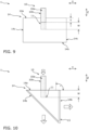
- the glass fibers 10 are aligned perpendicular to the entrance surface 14a of the optical element, so that both a first angle ⁇ and a second angle ⁇ , see Figure 10 , 90°.
- the sheaths 10b of the glass fibers 10 each have a pump light trap 12 in the area in which the coatings 10c are removed, which can also be referred to as a sheath light remover 12 or as a stripping element 12 and is designed in the form of annular depressions 12.
- a sheath light remover 12 or as a stripping element 12 and is designed in the form of annular depressions 12.
- a tension element 13 is arranged across all the glass fibers.
- a mechanical tension for example in the form of compressive forces, can be exerted on the glass fibers 10 or at least their cores 10a via the tension element 13.
- the transmission or the optical properties of the signal light radiation A can be influenced in a targeted manner by adjusting the mechanical tension.
- the side surfaces 14c and the entrance surface 14a of the optical element 14 are optically roughened in order to promote the exit of interference radiation from the optical element 14.
- the underside of the optical element 14, which is covered by the optical coating 15, is optically smooth in order to promote the exit of the exit radiation A'.
- Figure 2 shows a schematic representation of an arrangement of glass fibers 10 from above.
- the cylindrical glass fibers 10 are arranged linearly without spacing in the transverse direction Y, so that the sheaths 10b of the immediately adjacent glass fibers 10 touch each other.
- the optical element 14 is rectangular or cuboid-shaped.
- Figure 3 shows a schematic representation of an arrangement of glass fibers 10 from above.
- the optical element 14 is rectangular or cuboid-shaped.
- the cylindrical glass fibers 10 are arranged in a semicircle and spaced apart from one another in the circumferential direction.
- Figure 4 shows a schematic representation of an arrangement of glass fibers 10 from above.
- the optical element 14 is circular or cylindrical.
- the cylindrical glass fibers 10 are arranged in a V-shape without any gaps, so that the sheaths 10b of the immediately adjacent glass fibers 10 touch each other.
- Figure 5 shows a schematic representation of an arrangement of glass fibers 10 from above.
- the optical element 14 is square or cuboid-shaped.
- a cylindrical glass fiber 10 forms the center or the axis of symmetry of a point-symmetrical circular arrangement in which several further cylindrical glass fibers 10 extend in a first inner ring and in a second outer ring around the center.
- Figure 6 shows a schematic representation of an arrangement of glass fibers 10 from above.
- the optical element 14 is triangular.
- Several square glass fibers 10 with square cores 10a and square claddings 10b form a rectangular arrangement.
- Figure 7 shows a schematic representation of glass fibers 10 with an optical element 14 from the side.
- the glass fibers 10 are arranged in a line next to one another and at a distance from one another in the transverse direction Y.
- the optical element 14 widens in the vertical direction Z from the entry surface 14a to the exit surface 14c in a step-like manner along all four side surfaces 14c. This allows the weight and volume of the optical element 14 to be reduced.
- the area of the entry surface 14a of the optical element 14 can also be minimized, which can promote the process of melting the material of the optical element 14.
- Figure 8 shows a schematic representation of glass fibers 10 with an optical element 14 from the side.
- the optical element 14 widens in the vertical direction Z from the entrance surface 14a to the exit surface 14c in a continuously and consistently uniform manner.
- Figure 9 shows a schematic representation of glass fibers 10 with an optical element 14 from the side.
- a groove-shaped depression 17 has been made in the transverse direction Y in the entry surface 14a of the optical element 14, which has a depth V in the vertical direction Z.
- the penetration depth W of the open ends 11 of the cores 10a and the claddings 10b of the glass fibers 10 into the optical element 14 thus only begins at the bottom of the depression 17, so that the open ends 11 of the glass fibers 10 are spaced from the entry surface 14a of the optical element 14 by the sum of the depth V and the penetration depth W.
- This can increase the mechanical stability of the connection of the glass fibers 10 to the optical element 14 without having to melt the open ends 11 of the glass fibers 10 deeper into the material of the optical element 14.
- Figure 10 shows a schematic representation of glass fibers 10 with an optical element 14 from the side.
- the glass fibers 10 are arranged linearly in the transverse direction Y.
- the optical element 14 has a triangular cross-section in the plane of the longitudinal direction X of the vertical direction Z, so that the exit radiation A' can exit the optical element 14 both in the longitudinal direction X to the right and diagonally to the bottom left.
- Figure 11 shows a schematic representation of glass fibers 10 with an optical element 14 from the side.
- the glass fibers 10 are arranged linearly in the longitudinal direction X.
- FIG 12 shows the representation of the Figure 1 with housing 16.
- the housing 16 can also be referred to as a housing plate 16, a frame 16, a fiber connector 16, a heat sink 16 or a frame 16.
- the optical element 14 is held on the housing 16 by a bracket 16b in such a way that the exit radiation A' can exit undisturbed in the vertical direction Z downwards, compare Figure 1 .
- the glass fibers 10 are held by the housing 16 by means of the tension element 13, in that the tension element 13 is fixed to the housing 16 by means of adhesive. is glued on.
- the housing 16 has several fastening elements 16a in the form of through-openings 16a in order to be mounted and held on a substrate by means of screws or the like through the through-openings 16a.
- the housing 16 can be closed accordingly by means of a cover or the like (not shown).
- the radiation emitted via the pump light trap 12 can be absorbed in the housing 16 together with the cover as a heat sink 16.
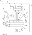
- Figure 13 shows a schematic representation of a processing device 2 according to the invention from the side.
- a processing device 2 according to the invention By means of such a processing device 2 according to the invention, the previously described fiber exit element 1 but also other fiber exit elements and comparable glass fiber components can be manufactured or processed.
- the processing device 2 has a housing 20 which holds the components or parts of the processing device 2 and encloses a work space (not designated) in which, for example, the previously described fiber exit element 1 can be processed or produced.
- the work space can be lockable and accessible to a person, for example by means of a door or flap.
- a movable receiving unit 21 is provided, by which a plurality of glass fibers 10 can be received and held, preferably in the region of their coatings 10c but optionally alternatively or additionally in the region of their sheaths 10b, for example by means of a mechanical holding element, for example as a gripper or the like, in order to be moved with the receiving unit 21 at least in one direction of movement B in the vertical direction Z.
- a movable receiving unit 22 is also provided, by which the optical element 14 can be received and held, for example by means of a mechanical holding element, for example as a gripper or the like, over its side surfaces 14c, in order to be moved with the receiving unit 22 at least in one direction of movement C in the vertical direction Z.
- the processing device 2 further comprises a first processing beam source 23 in the form of a first CO2 laser beam source 23, which can generate a first processing beam D in the form of a first CO2 laser beam D.
- the first processing beam D is directed by the first processing beam source 23 onto a first movable alignment element 23a in the form of a first pivotable mirror 23a.
- the first movable alignment element 23a is suspended accordingly on the housing 20 and adjustable by means of drives (not shown) so that the first processing beam D can be directed by the first movable alignment element 23a onto the entrance surface 14a of the optical element 14.
- the processing zone F of the entrance surface 14a of the optical element 14 can be directed by means of the first processing beam. heated and the material of the optical element 14 in this area is melted and made flowable.
- a second processing beam E in the form of a second CO2 laser beam E can also be used in the transverse direction Y from the opposite side of the optical element 14, which is preferably generated by a second processing beam source 24 in the form of a second CO2 laser beam source 24 and can be directed onto the processing zone F by means of a second movable alignment element 24a in the form of a second pivotable mirror 24a.
- the second processing beam E can also emanate from the first processing beam source 23, for example by means of a beam splitter.
- the processing zone F can also be referred to as a heating zone F or as a welding zone F.
- the processing device 2 makes it possible for the processing device 2 to independently carry out a process for connecting the open ends 11 of the glass fibers 10 to the optical element 14 in accordance with user-defined parameterization. If the glass fibers 10 have been arranged in the movable receiving unit 21 and the optical element 14 in the movable receiving unit 22 by a person, the processing or manufacturing process can be operated by the processing device 2 in such a way that the processing zone F is heated to a flowable state as described above.
- the glass fibers 10 can now be moved towards one another on one or both sides by their movable receiving unit 21 in the direction of movement B in the vertical direction Z downwards and/or the optical element 14 can be moved towards one another by its movable receiving unit 22 in the direction of movement C in the vertical direction Z upwards, so that the open ends 11 of the glass fibers 10 in the area of the processing zone F can penetrate into the flowable material of the entry surface 14a of the optical element 14 at the predetermined penetration depth W.
- the heating of the processing zone F by means of the two processing beams D, E can have been completed beforehand or can still be ongoing.
- the heating of the processing zone F can be stopped. Alternatively, the heating of the processing zone F can also be stopped before the penetration depth W is reached. In any case, the flowable material of the entry surface 14a of the optical element 14 can now melt the materials of the cores 10a and the jackets 10b of the glass fibers 10 in the area of the open ends 11 and thereby form a material bond upon cooling.
- the processing device 2 further comprises a first image capture unit 25 in the form of a first area camera 25, which is arranged centrally below the optical element 14 in the vertical direction Z and is aligned with the exit surface 14b of the optical element 14.
- the processing device 2 further comprises a second image capture unit 26 in the form of a second area camera 26, which is aligned at a height Z from above at an angle to the processing zone F of the entry surface 14a of the optical element 14.
- the open ends 11 of the glass fibers 10 relative to the optical element 14 can be aligned by the user by means of the two image capture units 25, 26, or can also be done automatically by the processing device 2.
- the processing device 2 further comprises an alignment unit 29 in the form of a gripper 29 that can be moved in translation and rotation, which can grip exactly one of the glass fibers 10 independently of the other glass fibers 10 in the area of its coating 10c and align it around the axis of its elongated extension relative to the optical element 14.
- the gripper 29 can be moved between the individual glass fibers 10 in the transverse direction Y and in the longitudinal direction X in order to reach and align each glass fiber 10. This enables a predetermined alignment relative to the optical element 14 for each glass fiber 10, whereby, for example, in the case of polarization-maintaining glass fibers 10 and/or glass fibers 10 with stress cores, the optical properties of the signal output radiation can be influenced.
- the processing device 2 further comprises a temperature detection unit 27 in the form of an infrared area camera 27, which is also aligned at a height Z from above at an angle to the processing zone F of the entry surface 14a of the optical element 14.
- the temperature detection unit 27 can be used to at least monitor the heating of the processing zone F, for example by the person. However, the temperature detection unit 27 can also be used by the processing device 2 to monitor the previously described process of heating the processing zone F and/or the previously described process of dipping the open ends 11 of the glass fibers 10 into the flowable material of the processing zone F of the entry surface 14a of the optical element 14 and/or to carry them out in an independently controlled manner depending on the detected temperature of the processing zone F.
- the processing device 2 further comprises a cooling unit 28 in the form of an air blower 28, which is directed towards the exit surface 14b of the optical element 14.
- a cooling unit 28 in the form of an air blower 28, which is directed towards the exit surface 14b of the optical element 14.
- an air flow of ambient air can be generated and directed towards the exit surface 14b of the optical element 14, so that heat can be actively removed from the optical element 14 outside the processing zone. F can be dissipated. In this way, the heating of the optical element 14 outside the processing zone F can be deliberately kept low.
- the previously described pump light traps 12 can also be introduced into the claddings 10b of the glass fibers 10 in a subsequent production step.
- the fiber exit element 1 can be removed by the user from the working space of the processing device 2 and provided with the tension element 13 in an additional manufacturing step.
Landscapes
- Physics & Mathematics (AREA)
- General Physics & Mathematics (AREA)
- Optics & Photonics (AREA)
- Engineering & Computer Science (AREA)
- Plasma & Fusion (AREA)
- Optical Couplings Of Light Guides (AREA)
- Paper (AREA)
Applications Claiming Priority (3)
| Application Number | Priority Date | Filing Date | Title |
|---|---|---|---|
| DE102019116839 | 2019-06-21 | ||
| EP20735288.1A EP3987331A1 (fr) | 2019-06-21 | 2020-06-19 | Élément de sortie en fibres |
| PCT/EP2020/067248 WO2020254661A1 (fr) | 2019-06-21 | 2020-06-19 | Élément de sortie en fibres |
Related Parent Applications (1)
| Application Number | Title | Priority Date | Filing Date |
|---|---|---|---|
| EP20735288.1A Division EP3987331A1 (fr) | 2019-06-21 | 2020-06-19 | Élément de sortie en fibres |
Publications (2)
| Publication Number | Publication Date |
|---|---|
| EP4431990A2 true EP4431990A2 (fr) | 2024-09-18 |
| EP4431990A3 EP4431990A3 (fr) | 2024-11-27 |
Family
ID=71401718
Family Applications (3)
| Application Number | Title | Priority Date | Filing Date |
|---|---|---|---|
| EP20735288.1A Pending EP3987331A1 (fr) | 2019-06-21 | 2020-06-19 | Élément de sortie en fibres |
| EP24183678.2A Pending EP4431990A3 (fr) | 2019-06-21 | 2020-06-19 | Élément de sortie en fibres |
| EP24178966.8A Pending EP4414759A3 (fr) | 2019-06-21 | 2020-06-19 | Élément de sortie en fibres |
Family Applications Before (1)
| Application Number | Title | Priority Date | Filing Date |
|---|---|---|---|
| EP20735288.1A Pending EP3987331A1 (fr) | 2019-06-21 | 2020-06-19 | Élément de sortie en fibres |
Family Applications After (1)
| Application Number | Title | Priority Date | Filing Date |
|---|---|---|---|
| EP24178966.8A Pending EP4414759A3 (fr) | 2019-06-21 | 2020-06-19 | Élément de sortie en fibres |
Country Status (3)
| Country | Link |
|---|---|
| US (1) | US12498521B2 (fr) |
| EP (3) | EP3987331A1 (fr) |
| WO (1) | WO2020254661A1 (fr) |
Families Citing this family (6)
| Publication number | Priority date | Publication date | Assignee | Title |
|---|---|---|---|---|
| EP4264345A2 (fr) | 2020-12-16 | 2023-10-25 | Fiberbridge Photonics Gmbh | Élément de sortie en fibres |
| DE102022101915B3 (de) | 2022-01-27 | 2023-03-16 | FiberBridge Photonics GmbH | Faseraustrittselement |
| CN114755738B (zh) * | 2022-04-18 | 2025-06-06 | 山东大学 | 一种碳纤维布自动检偏矫正装置及其控制方法 |
| DE102022129645A1 (de) | 2022-11-09 | 2024-05-16 | FiberBridge Photonics GmbH | Glasfaseroptisches Bauteil |
| US20240219657A1 (en) * | 2023-01-04 | 2024-07-04 | Mo-Link Technology Limited | Optical fiber coupler and alignment method |
| DE102023133492A1 (de) * | 2023-11-30 | 2025-06-05 | FiberBridge Photonics GmbH | Strahlführungsvorrichtung zur Führung von Signallichtstrahlung |
Citations (3)
| Publication number | Priority date | Publication date | Assignee | Title |
|---|---|---|---|---|
| US6819858B2 (en) | 2000-10-26 | 2004-11-16 | Shipley Company, L.L.C. | Fiber array with V-groove chip and mount |
| US6978073B2 (en) | 2001-12-19 | 2005-12-20 | Nippon Telegraph & Telephone Corporation | Optical fiber array |
| US20120045169A1 (en) | 2010-08-23 | 2012-02-23 | Lockheed Martin Corporation | Optical-fiber array method and apparatus |
Family Cites Families (6)
| Publication number | Priority date | Publication date | Assignee | Title |
|---|---|---|---|---|
| JP2007065437A (ja) * | 2005-09-01 | 2007-03-15 | Juki Corp | ファイバーコリメータ |
| JP2007178603A (ja) * | 2005-12-27 | 2007-07-12 | Topcon Corp | 光部品およびその製造方法 |
| JP2008151897A (ja) * | 2006-12-15 | 2008-07-03 | Topcon Corp | 光分波装置 |
| US8582934B2 (en) * | 2007-11-12 | 2013-11-12 | Lightlab Imaging, Inc. | Miniature optical elements for fiber-optic beam shaping |
| JP2014191277A (ja) | 2013-03-28 | 2014-10-06 | Sumitomo Electric Ind Ltd | レーザ伝送用ファイバ及びレーザ伝送用ファイバの製造方法 |
| US10261329B2 (en) * | 2016-08-26 | 2019-04-16 | Nlight, Inc. | Fiber combiner with input port dump |
-
2020
- 2020-06-19 US US17/620,227 patent/US12498521B2/en active Active
- 2020-06-19 EP EP20735288.1A patent/EP3987331A1/fr active Pending
- 2020-06-19 WO PCT/EP2020/067248 patent/WO2020254661A1/fr not_active Ceased
- 2020-06-19 EP EP24183678.2A patent/EP4431990A3/fr active Pending
- 2020-06-19 EP EP24178966.8A patent/EP4414759A3/fr active Pending
Patent Citations (3)
| Publication number | Priority date | Publication date | Assignee | Title |
|---|---|---|---|---|
| US6819858B2 (en) | 2000-10-26 | 2004-11-16 | Shipley Company, L.L.C. | Fiber array with V-groove chip and mount |
| US6978073B2 (en) | 2001-12-19 | 2005-12-20 | Nippon Telegraph & Telephone Corporation | Optical fiber array |
| US20120045169A1 (en) | 2010-08-23 | 2012-02-23 | Lockheed Martin Corporation | Optical-fiber array method and apparatus |
Also Published As
| Publication number | Publication date |
|---|---|
| EP3987331A1 (fr) | 2022-04-27 |
| US12498521B2 (en) | 2025-12-16 |
| EP4414759A3 (fr) | 2024-11-13 |
| EP4431990A3 (fr) | 2024-11-27 |
| EP4414759A2 (fr) | 2024-08-14 |
| WO2020254661A1 (fr) | 2020-12-24 |
| US20220244461A1 (en) | 2022-08-04 |
Similar Documents
| Publication | Publication Date | Title |
|---|---|---|
| EP4414759A2 (fr) | Élément de sortie en fibres | |
| DE69015927T2 (de) | Vorrichtung und Verfahren für die Herstellung von permanenten faseroptischen Spleissen niedriger Dämpfung. | |
| DE112011102811B4 (de) | Faseroptikarrayverfahren und -vorrichtung | |
| EP2596901B1 (fr) | Dispositif de rayonnement optique pour une installation destinée à la fabrication de pièces à usiner tridimensionnelles par rayonnement de couches de pulvérisation d'une poudre de matière brute avec un rayonnement laser | |
| DE60313491T2 (de) | Linse auf optischer faser oder auf wellenleiter | |
| DE60011995T2 (de) | Herstellung von kollimatoren mit optischen fasern, angespleisst an optische elemente mit grösserem querschnitt | |
| DE102019122047B4 (de) | Ausrichteinheit, Sensormodul umfassend dieselbe und Laserbearbeitungssystem umfassend das Sensormodul | |
| DE10352590A1 (de) | Verfahren zum Herstellen einer optischen Faser mit einer Auskoppelstelle für Streulicht, Verwendung einer optischen Faser und Vorrichtung zum Überwachen von in einer optischen Faser geführter Lichtleistung | |
| DE102010015023B4 (de) | Verfahren und Vorrichtung zur Qualitätssicherung und Prozesskontrolle bei der Laserbearbeitung von Werkstücken | |
| EP2184139B1 (fr) | Dispositif de traitement en 3D hautement dynamique d'une pièce usinée à l'aide d'un rayon laser | |
| DE2640422A1 (de) | Verfahren und vorrichtung zum verbinden von lichtleitfasern | |
| DE3932458A1 (de) | Verfahren zum gegenseitigen ausrichten einer optischen energiequelle und eines lichtleiters sowie vorrichtung zur durchfuehrung des verfahrens | |
| DE69924544T2 (de) | Faserlaser | |
| WO2021047732A1 (fr) | Dispositif et procédé pour détecter une température d'un outil de connexion lors d'un soudage par électrons au laser | |
| DE69626559T2 (de) | Laserlichtquelle und Herstellungsverfahren | |
| EP4264345A2 (fr) | Élément de sortie en fibres | |
| DE10127331A1 (de) | Verfahren zum Verbinden einer optischen Faser mit einer GRIN-Linse sowie Verfahren zur Herstellung optischer Filtermodule und verfahrensgem. hergestellte Filtermodule | |
| EP4492104A1 (fr) | Connecteur pour guide d'ondes optique multiple et connecteur pour guide d'ondes optique utilisant un tel connecteur | |
| DE102019116812A1 (de) | Bearbeitungsvorrichtung für Glasfasern | |
| DE19927167A1 (de) | Koppelelement zur Kopplung hochintensiver Lichtstrahlung und Verfahren zu dessen Herstellung sowie Anordnung aus Koppelelementen zur Kopplung hochintensiver Lichtstrahlung | |
| EP3811134B1 (fr) | Câble à fibres optiques doté d'un capteur de lumière de gainage et dispositifs de réglage, d'essai et de surveillance associés | |
| EP4469845A1 (fr) | Élément de sortie en fibres | |
| DE3733987A1 (de) | Verfahren und vorrichtung zur herstellung von verbindungsstellen fuer lichtleitfasern an verbindungssteckern | |
| DE102022110078A1 (de) | Vorrichtung und Verfahren zur Modifikation des Strahlprofils eines Laserstrahls | |
| DE102022129645A1 (de) | Glasfaseroptisches Bauteil |
Legal Events
| Date | Code | Title | Description |
|---|---|---|---|
| PUAI | Public reference made under article 153(3) epc to a published international application that has entered the european phase |
Free format text: ORIGINAL CODE: 0009012 |
|
| STAA | Information on the status of an ep patent application or granted ep patent |
Free format text: STATUS: THE APPLICATION HAS BEEN PUBLISHED |
|
| AC | Divisional application: reference to earlier application |
Ref document number: 3987331 Country of ref document: EP Kind code of ref document: P |
|
| AK | Designated contracting states |
Kind code of ref document: A2 Designated state(s): AL AT BE BG CH CY CZ DE DK EE ES FI FR GB GR HR HU IE IS IT LI LT LU LV MC MK MT NL NO PL PT RO RS SE SI SK SM TR |
|
| PUAL | Search report despatched |
Free format text: ORIGINAL CODE: 0009013 |
|
| AK | Designated contracting states |
Kind code of ref document: A3 Designated state(s): AL AT BE BG CH CY CZ DE DK EE ES FI FR GB GR HR HU IE IS IT LI LT LU LV MC MK MT NL NO PL PT RO RS SE SI SK SM TR |
|
| RIC1 | Information provided on ipc code assigned before grant |
Ipc: G02B 6/32 20060101ALI20241022BHEP Ipc: G02B 6/26 20060101ALI20241022BHEP Ipc: G02B 6/255 20060101ALI20241022BHEP Ipc: G02B 6/34 20060101AFI20241022BHEP |
|
| STAA | Information on the status of an ep patent application or granted ep patent |
Free format text: STATUS: REQUEST FOR EXAMINATION WAS MADE |
|
| 17P | Request for examination filed |
Effective date: 20250527 |
|
| STAA | Information on the status of an ep patent application or granted ep patent |
Free format text: STATUS: EXAMINATION IS IN PROGRESS |