EP4431991A1 - Optisches modul, ferrule und faseroptischer stecker - Google Patents
Optisches modul, ferrule und faseroptischer stecker Download PDFInfo
- Publication number
- EP4431991A1 EP4431991A1 EP22903014.3A EP22903014A EP4431991A1 EP 4431991 A1 EP4431991 A1 EP 4431991A1 EP 22903014 A EP22903014 A EP 22903014A EP 4431991 A1 EP4431991 A1 EP 4431991A1
- Authority
- EP
- European Patent Office
- Prior art keywords
- optical
- optical fiber
- unit
- fiber
- module
- Prior art date
- Legal status (The legal status is an assumption and is not a legal conclusion. Google has not performed a legal analysis and makes no representation as to the accuracy of the status listed.)
- Pending
Links
Images



Classifications
-
- G—PHYSICS
- G02—OPTICS
- G02B—OPTICAL ELEMENTS, SYSTEMS OR APPARATUS
- G02B6/00—Light guides; Structural details of arrangements comprising light guides and other optical elements, e.g. couplings
- G02B6/24—Coupling light guides
- G02B6/42—Coupling light guides with opto-electronic elements
- G02B6/4292—Coupling light guides with opto-electronic elements the light guide being disconnectable from the opto-electronic element, e.g. mutually self aligning arrangements
-
- G—PHYSICS
- G02—OPTICS
- G02B—OPTICAL ELEMENTS, SYSTEMS OR APPARATUS
- G02B6/00—Light guides; Structural details of arrangements comprising light guides and other optical elements, e.g. couplings
- G02B6/24—Coupling light guides
- G02B6/42—Coupling light guides with opto-electronic elements
- G02B6/4201—Packages, e.g. shape, construction, internal or external details
- G02B6/4246—Bidirectionally operating package structures
-
- G—PHYSICS
- G02—OPTICS
- G02B—OPTICAL ELEMENTS, SYSTEMS OR APPARATUS
- G02B6/00—Light guides; Structural details of arrangements comprising light guides and other optical elements, e.g. couplings
- G02B6/24—Coupling light guides
- G02B6/36—Mechanical coupling means
- G02B6/38—Mechanical coupling means having fibre to fibre mating means
- G02B6/3807—Dismountable connectors, i.e. comprising plugs
-
- G—PHYSICS
- G02—OPTICS
- G02B—OPTICAL ELEMENTS, SYSTEMS OR APPARATUS
- G02B6/00—Light guides; Structural details of arrangements comprising light guides and other optical elements, e.g. couplings
- G02B6/24—Coupling light guides
- G02B6/36—Mechanical coupling means
- G02B6/38—Mechanical coupling means having fibre to fibre mating means
- G02B6/3807—Dismountable connectors, i.e. comprising plugs
- G02B6/3833—Details of mounting fibres in ferrules; Assembly methods; Manufacture
-
- G—PHYSICS
- G02—OPTICS
- G02B—OPTICAL ELEMENTS, SYSTEMS OR APPARATUS
- G02B6/00—Light guides; Structural details of arrangements comprising light guides and other optical elements, e.g. couplings
- G02B6/24—Coupling light guides
- G02B6/42—Coupling light guides with opto-electronic elements
- G02B6/4201—Packages, e.g. shape, construction, internal or external details
- G02B6/4204—Packages, e.g. shape, construction, internal or external details the coupling comprising intermediate optical elements, e.g. lenses, holograms
- G02B6/4215—Packages, e.g. shape, construction, internal or external details the coupling comprising intermediate optical elements, e.g. lenses, holograms the intermediate optical elements being wavelength selective optical elements, e.g. variable wavelength optical modules or wavelength lockers
-
- G—PHYSICS
- G02—OPTICS
- G02B—OPTICAL ELEMENTS, SYSTEMS OR APPARATUS
- G02B6/00—Light guides; Structural details of arrangements comprising light guides and other optical elements, e.g. couplings
- G02B6/24—Coupling light guides
- G02B6/42—Coupling light guides with opto-electronic elements
- G02B6/4201—Packages, e.g. shape, construction, internal or external details
- G02B6/4219—Mechanical fixtures for holding or positioning the elements relative to each other in the couplings; Alignment methods for the elements, e.g. measuring or observing methods especially used therefor
- G02B6/4236—Fixing or mounting methods of the aligned elements
- G02B6/424—Mounting of the optical light guide
-
- H—ELECTRICITY
- H04—ELECTRIC COMMUNICATION TECHNIQUE
- H04B—TRANSMISSION
- H04B10/00—Transmission systems employing electromagnetic waves other than radio-waves, e.g. infrared, visible or ultraviolet light, or employing corpuscular radiation, e.g. quantum communication
- H04B10/25—Arrangements specific to fibre transmission
-
- H—ELECTRICITY
- H04—ELECTRIC COMMUNICATION TECHNIQUE
- H04J—MULTIPLEX COMMUNICATION
- H04J14/00—Optical multiplex systems
- H04J14/02—Wavelength-division multiplex systems
-
- H—ELECTRICITY
- H04—ELECTRIC COMMUNICATION TECHNIQUE
- H04J—MULTIPLEX COMMUNICATION
- H04J14/00—Optical multiplex systems
- H04J14/05—Spatial multiplexing systems
- H04J14/052—Spatial multiplexing systems using multicore fibre
-
- G—PHYSICS
- G02—OPTICS
- G02B—OPTICAL ELEMENTS, SYSTEMS OR APPARATUS
- G02B6/00—Light guides; Structural details of arrangements comprising light guides and other optical elements, e.g. couplings
- G02B6/24—Coupling light guides
- G02B6/26—Optical coupling means
- G02B6/28—Optical coupling means having data bus means, i.e. plural waveguides interconnected and providing an inherently bidirectional system by mixing and splitting signals
- G02B6/293—Optical coupling means having data bus means, i.e. plural waveguides interconnected and providing an inherently bidirectional system by mixing and splitting signals with wavelength selective means
- G02B6/29346—Optical coupling means having data bus means, i.e. plural waveguides interconnected and providing an inherently bidirectional system by mixing and splitting signals with wavelength selective means operating by wave or beam interference
- G02B6/29361—Interference filters, e.g. multilayer coatings, thin film filters, dichroic splitters or mirrors based on multilayers, WDM filters
- G02B6/29362—Serial cascade of filters or filtering operations, e.g. for a large number of channels
-
- G—PHYSICS
- G02—OPTICS
- G02B—OPTICAL ELEMENTS, SYSTEMS OR APPARATUS
- G02B6/00—Light guides; Structural details of arrangements comprising light guides and other optical elements, e.g. couplings
- G02B6/24—Coupling light guides
- G02B6/26—Optical coupling means
- G02B6/28—Optical coupling means having data bus means, i.e. plural waveguides interconnected and providing an inherently bidirectional system by mixing and splitting signals
- G02B6/293—Optical coupling means having data bus means, i.e. plural waveguides interconnected and providing an inherently bidirectional system by mixing and splitting signals with wavelength selective means
- G02B6/29379—Optical coupling means having data bus means, i.e. plural waveguides interconnected and providing an inherently bidirectional system by mixing and splitting signals with wavelength selective means characterised by the function or use of the complete device
- G02B6/2938—Optical coupling means having data bus means, i.e. plural waveguides interconnected and providing an inherently bidirectional system by mixing and splitting signals with wavelength selective means characterised by the function or use of the complete device for multiplexing or demultiplexing, i.e. combining or separating wavelengths, e.g. 1xN, NxM
-
- G—PHYSICS
- G02—OPTICS
- G02B—OPTICAL ELEMENTS, SYSTEMS OR APPARATUS
- G02B6/00—Light guides; Structural details of arrangements comprising light guides and other optical elements, e.g. couplings
- G02B6/24—Coupling light guides
- G02B6/36—Mechanical coupling means
- G02B6/38—Mechanical coupling means having fibre to fibre mating means
- G02B6/3807—Dismountable connectors, i.e. comprising plugs
- G02B6/3873—Connectors using guide surfaces for aligning ferrule ends, e.g. tubes, sleeves, V-grooves, rods, pins, balls
- G02B6/3885—Multicore or multichannel optical connectors, i.e. one single ferrule containing more than one fibre, e.g. ribbon type
Definitions
- a single-fiber bidirectional optical module is widely used in a communication network because the single-fiber bidirectional optical module can be used to save an optical fiber resource and increase a communication system capacity.
- a baseband unit baseband unit, BBU
- an active antenna unit active antenna unit, AAU
- a multiplexer/demultiplexer may receive and send optical signals through an optical fiber #1 at the same time, and this causes a conflict.
- the single-fiber bidirectional optical module cannot be applicable to a scenario in which the single-fiber bidirectional optical module is directly connected to the multiplexer/demultiplexer.
- the single-fiber bidirectional optical module may fail to meet a requirement for capacity expansion.
- Embodiments of this application provide an optical module, a ferrule, and an optical fiber connector, so that a plurality of optical signals can be transmitted through one optical interface, and the optical module is enabled to meet a requirement for system capacity expansion.
- an optical module includes N optical units, a demultiplexing unit, and an optical fiber connector, where the optical fiber connector includes a ferrule and M optical fibers, the M optical fibers are disposed in the ferrule, each of the M optical fibers corresponds to at least one of the N optical units, and optical units corresponding to any two of the M optical fibers are different, where M is an integer greater than or equal to 2, and N is an integer greater than or equal to M.
- a first optical unit in the N optical units is configured to receive or send an optical signal, and the first optical unit is any one of the N optical units.
- a first optical fiber in the M optical fibers is configured to transmit an optical signal received by an optical unit corresponding to the first optical fiber, and/or the first optical fiber is configured to transmit an optical signal received from the optical unit corresponding to the first optical fiber, where the first optical fiber is any one of the M optical fibers.
- the demultiplexing unit is configured to send, to the first optical unit, an optical signal received from an optical fiber corresponding to the first optical unit, and/or configured to send, to the first optical fiber, the optical signal received from the optical unit corresponding to the first optical fiber.
- two or more optical fibers are built in the ferrule included in the optical fiber connector.
- more optical signals can be transmitted by using one optical module, to meet a requirement for system capacity expansion.
- the optical module includes three optical units, and two optical fibers are built in the ferrule, one of the optical fibers corresponds to one optical unit, to be specific, is configured to transmit an optical signal with one wavelength, and the other optical fiber corresponds to the other two optical units, to be specific, is configured to transmit optical signals with two wavelengths.
- the optical module is configured to transmit three optical signals in total.
- the optical module provided in this application can transmit more optical signals. If the optical module is deployed on a baseband module, and the three optical units included in the optical module respectively communicate with three radio frequency modules, the baseband module may communicate with the three radio frequency modules by using the optical module, while the baseband module can only communicate with a maximum of two radio frequency modules by using the single-fiber bidirectional optical module. Therefore, when the optical module is deployed on the baseband module, the baseband module may communicate with more radio frequency devices without increasing a quantity of optical modules, to meet the requirement for system capacity expansion. In addition, because the quantity of optical modules does not need to be increased, a panel size of the baseband module may also remain unchanged.
- the optical fiber connector is connected to another unit included in the optical module through spatial light instead of the optical fiber in the ferrule.
- wavelengths of optical signals corresponding to any two of the N optical units are different.
- a length of the first optical fiber is equal to a length of the ferrule.
- a length of the first optical fiber is greater than a length of the ferrule.
- the N optical units include a first optical receiving unit and a first optical sending unit
- the M optical fibers include a second optical fiber and a third optical fiber.
- the second optical fiber is configured to transmit a first optical signal received by the first optical receiving unit.
- the third optical fiber is configured to transmit a second optical signal received from the first optical sending unit.
- optical module because two optical fibers are in one ferrule, optical signals can be received and sent through different optical fibers without adding an optical interface.
- the optical module provided in this application may be directly connected to the existing multiplexer/demultiplexer.
- the demultiplexing unit includes a first filter and a second filter.
- the first filter is configured to: reflect the first optical signal and transmit the second optical signal.
- the second filter is configured to reflect the second optical signal.
- the N optical units further include a second optical receiving unit and a second optical sending unit
- the M optical fibers further include a fourth optical fiber and a fifth optical fiber.
- the fourth optical fiber is configured to transmit a third optical signal received by the second optical receiving unit.
- the fifth optical fiber is configured to transmit a fourth optical signal received from the second optical sending unit.
- the N optical units further include a second optical receiving unit and a second optical sending unit
- the M optical fibers further include a sixth optical fiber.
- the sixth optical fiber is configured to transmit a fourth optical signal received from the second optical sending unit.
- the sixth optical fiber is further configured to transmit a third optical signal received by the second optical receiving unit.
- the demultiplexing unit includes a first filter, a second filter, a third filter, and a fourth filter.
- the first filter is configured to: reflect the first optical signal and transmit another optical signal.
- the second filter is configured to: reflect the second optical signal and transmit another optical signal.
- the third filter is configured to: reflect the third optical signal and transmit another optical signal.
- the fourth filter is configured to: transmit the fourth optical signal and reflect another optical signal.
- the N optical fibers are arranged side by side in a same direction in the ferrule.
- the N optical fibers are arranged around a longitudinal axis of the ferrule.
- the N optical fibers include one or more multi-core optical fibers.
- each optical core in a single multi-core optical fiber is configured to transmit optical signals with different wavelengths.
- a ferrule is provided.
- M optical fibers are built in the ferrule, and each of the M optical fibers is configured to transmit an optical signal with at least one wavelength, where M is an integer greater than or equal to 2.
- the baseband module may communicate with a maximum of three radio frequency modules by using the three optical signals, while the baseband module can only communicate with a maximum of two radio frequency modules by using a single-fiber bidirectional optical module. Therefore, when the optical module in which the ferrule is used is deployed on the baseband module, the baseband module may communicate with more radio frequency devices without increasing a quantity of optical modules, to meet the requirement for system capacity expansion. In addition, because the quantity of optical modules does not need to be increased, a panel size of the baseband module may also remain unchanged.
- the RRU and the antenna may be implemented by an active antenna unit (active antenna unit, AAU).
- AAU active antenna unit
- the AAU is a radio frequency module. Transmission between the BBU and the AAU or transmission between the DU and the RRU may be referred to as fronthaul.
- One of core links of optical fiber communication is conversion between an optical signal and an electrical signal.
- an optical signal carrying information is transmitted in an optical fiber, and information transmission with low costs and a low loss can be implemented by using a passive transmission feature of light in the optical fiber.
- an information processing device like a computer uses an electrical signal, and this requires mutual conversion between the electrical signal and the optical signal in a signal transmission process.
- An optical module implements the foregoing optical-to-electrical conversion function in the field of optical fiber communication technologies, and mutual conversion between the optical signal and the electrical signal is a core function of the optical module.
- the optical module is a key component in an optical communication system.
- the optical module includes a transmitting end and a receiving end.
- the transmitting end mainly implements an optical transmission function through a laser
- the receiving end mainly implements an optical receiving function through a photodetector.
- Commonly used optical modules mainly include a two-fiber bidirectional optical module with a transmitting end and a receiving end that are separate, and a single-fiber bidirectional (Bidirectional, Bidi) optical module with a transmitting end and a receiving end that are combined.
- the optical module may be in a form of a pluggable optical interface.
- One optical interface has one ferrule, and one ferrule includes one optical fiber.
- the two-fiber bidirectional optical module has two optical interfaces.
- An optical fiber in a ferrule disposed in one of the optical interfaces is used by the transmitting end to output an optical signal
- an optical fiber in a ferrule disposed in the other optical interface is used by the receiving end to receive an optical signal.
- An optical fiber in a ferrule disposed in an optical interface of the single-fiber bidirectional optical module may be used by the transmitting end to output an optical signal, and may also be used by the receiving end to receive an optical signal.
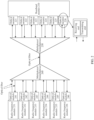
- FIG. 2 is a schematic diagram of an optical fiber transmission system.
- a baseband module 210 may be connected to a plurality of two-fiber bidirectional optical modules (221 to 226), a plurality of radio frequency modules (231 to 236) are respectively connected to two-fiber bidirectional optical modules (241 to 246).
- a multiplexer/demultiplexer 250 is disposed on a side of the baseband module 210, and a multiplexer/demultiplexer 260 may be disposed on a side of the radio frequency module.
- each optical module in FIG. 2 includes one transmitting end and one receiving end, and the transmitting end and the receiving end each are connected to one optical fiber.
- transmitting ends in the plurality of two-fiber bidirectional optical modules (221 to 226) connected to the baseband module 210 may transmit signals to the multiplexer/demultiplexer 250 through optical fibers, and the multiplexer/demultiplexer 250 may combine a plurality of optical signals, and then transmit the plurality of optical signals to the multiplexer/demultiplexer 260 through one optical fiber.
- the multiplexer/demultiplexer 260 then splits the received optical signals based on wavelengths, and sends the optical signals to the plurality of two-fiber bidirectional optical modules (241 to 246) respectively.
- the two-fiber bidirectional optical modules (241 to 246) connected to the radio frequency modules (231 to 236) may also send optical signals to the two-fiber bidirectional optical modules (221 to 216) connected to the baseband module 210.
- the two-fiber bidirectional optical module connected to the baseband module may be replaced with a single-fiber bidirectional optical module.
- the single-fiber bidirectional optical module receives and sends optical signals through one optical fiber. Therefore, when the baseband module communicates with a same quantity of radio frequency modules, a quantity of optical fibers can be decreased by using the single-fiber bidirectional optical module.
- one optical interface in the optical module has one ferrule, and one ferrule has one optical fiber. Therefore, a quantity of optical interfaces decreases as the quantity of optical fibers decreases.
- the single-fiber bidirectional optical module on the baseband module is an optical module with two optical interfaces (for example, a dual small form-factor pluggable (dual small form-factor pluggable, DSFP) optical module), when the quantity of optical interfaces decreases, a quantity of optical modules used by the baseband module decreases.
- the baseband module may communicate with more radio frequency modules by using the single-fiber bidirectional optical module, so that a requirement for capacity expansion can be met when the size of the baseband module remains unchanged.
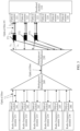
- an optical fiber transmission system shown in FIG. 3 may enable the baseband module 210 to communicate with more radio frequency devices when a panel size of the baseband module 210 remains unchanged.
- an optical fiber #1 of the optical module 321 is configured to receive an optical signal with a wavelength of ⁇ 1, and is also configured to send an optical signal with a wavelength of ⁇ 2. If an optical signal received by a multiplexer/demultiplexer 250 from a multiplexer/demultiplexer 260 includes the optical signal with a wavelength of ⁇ 1, and the optical module 321 sends the optical signal with a wavelength of ⁇ 2 through the optical fiber #1, the multiplexer/demultiplexer 250 cannot receive the optical signal with a wavelength of ⁇ 2 from the optical module 321 through the optical fiber #1, and cannot send the optical signal with a wavelength of ⁇ 1 to the optical module 321 through the optical fiber #1. Therefore, in the optical fiber transmission system shown in FIG.
- a multiplexer/demultiplexer 271 and a multiplexer/demultiplexer 272 need to be additionally added on a side of the baseband module.
- the multiplexer/demultiplexer 271 receives the optical signal with a wavelength of ⁇ 1 from the multiplexer/demultiplexer 250 through one optical fiber, and sends the optical signal with a wavelength of ⁇ 1 to the optical module 321 through the optical fiber #1.
- the multiplexer/demultiplexer 251 is further configured to: receive the optical signal with a wavelength of ⁇ 2 from the optical module 321 through the optical fiber #1, and send the optical signal with a wavelength of ⁇ 2 to the multiplexer/demultiplexer 250 through another optical fiber.
- the multiplexer/demultiplexer 272 and the multiplexer/demultiplexer 273 have similar functions.
- embodiments of this application provide a ferrule, an optical fiber connector, and an optical module, to expect to transmit a plurality of optical signals through one optical interface, so that the optical module meets the requirement for capacity expansion.
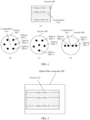
- FIG. 4 is a schematic diagram of a structure of a ferrule according to an embodiment of this application.
- M optical fibers are built in the ferrule 400.
- the M optical fibers are an optical fiber 1 to an optical fiber M.
- M is an integer greater than or equal to 2.
- the optical fiber 1 to the optical fiber M each are configured to transmit an optical signal with at least one wavelength, to be specific, a first optical fiber in the optical fiber 1 to the optical fiber M is configured to transmit an optical signal with one wavelength, or the first optical fiber is configured to transmit optical signals with a plurality of wavelengths, and the first optical fiber is any one of the optical fiber 1 to the optical fiber M.
- wavelengths of optical signals transmitted by any two of the optical fiber 1 to the optical fiber M are different.
- the optical fiber 1 is configured to transmit an optical signal 1
- the optical fiber 2 is configured to transmit an optical signal 2
- the optical fiber M is configured to transmit an optical signal M
- wavelengths of any two of the optical signal 1 to the optical signal M are different.
- the ferrule provided in this embodiment of this application because two or more optical fibers are built in the ferrule, and each optical fiber is configured to transmit the optical signal with at least one wavelength, at least two optical signals can be transmitted by using one ferrule. If the ferrule is used in an optical module, the at least two optical signals can be transmitted through one optical interface. This helps meet a requirement for system capacity expansion.
- the ferrule provided in this embodiment of this application may be used to transmit more optical signals with different wavelengths.
- three optical signals may be transmitted by using one ferrule.
- the baseband module may communicate with a maximum of three radio frequency modules by using the three optical signals, while the baseband module can only communicate with a maximum of two radio frequency modules by using a single-fiber bidirectional optical module. Therefore, when the optical module in which the ferrule is used is deployed on the baseband module, the baseband module may communicate with more radio frequency devices without increasing a quantity of optical modules, to meet the requirement for system capacity expansion.
- each of the three optical fibers built in the ferrule is configured to transmit a plurality of optical signals with different wavelengths
- the baseband module may communicate with more radio frequency modules.
- a panel size of the baseband module may also remain unchanged.
- optical signals with different wavelengths may be transmitted through different optical fibers by using one ferrule. If the ferrule is used in the optical module, because each optical fiber of the optical module is configured to transmit optical signals with different wavelengths, when the optical module is connected to a multiplexer/demultiplexer, a case in which the multiplexer/demultiplexer receives and sends optical signals through one optical fiber at the same time does not occur. Therefore, an additional multiplexer/demultiplexer does not need to be added between the optical module and the multiplexer/demultiplexer.
- the optical module in which the ferrule provided in this embodiment of this application is used is deployed on the baseband module 210 shown in FIG. 3
- the optical module may be directly connected to the multiplexer/demultiplexer 250, and does not need to be connected to the multiplexer/demultiplexer 250 by using the additional multiplexers/demultiplexers (271 to 273), to reduce complexity of the optical fiber transmission system.
- the M optical fibers are arranged around a longitudinal axis of the ferrule.
- a transverse cross-sectional view of the ferrule is shown in (b) in FIG. 4 .
- one of the M optical fibers is located at a longitudinal axis of the ferrule, and remaining optical fibers are arranged around the longitudinal axis of the ferrule.
- one of the M optical fibers is located at the longitudinal axis of the ferrule, and the remaining optical fibers are arranged around the longitudinal axis of the ferrule, a transverse cross-sectional view of the ferrule is shown in (c) in FIG. 4 .
- the M optical fibers are arranged side by side in a same direction in the ferrule.
- a transverse cross-sectional view of the ferrule is shown in (d) in FIG. 4 .
- distances between different optical fibers of the M optical fibers and the longitudinal axis of the ferrule may be equal or not equal.
- a distance between the optical fiber 1 and the longitudinal axis of the ferrule may be equal to a distance between the optical fiber 2 and the longitudinal axis of the ferrule; or a distance between the optical fiber 1 and the longitudinal axis of the ferrule may not be equal to a distance between the optical fiber 2 and the longitudinal axis of the ferrule.
- a distance between two adjacent optical fibers of the M optical fibers may be equal or not equal.
- a distance between the optical fiber 1 and the optical fiber 2 may be equal to a distance between the optical fiber 2 and the optical fiber 3; or a distance between the optical fiber 1 and the optical fiber 2 may not be equal to a distance between the optical fiber 2 and the optical fiber 3.
- the M optical fibers may include a single-core optical fiber, a multi-core optical fiber (multi-core optical fiber, MCF), a single-mode optical fiber, a few-mode optical fiber, a single-core few-mode optical fiber, and a multi-core few-mode optical fiber.
- types of all of the M optical fibers may be the same, or types of different optical fibers of the M optical fibers may be different. This is not limited in this embodiment of this application.
- the M optical fibers include one or more multi-core optical fibers, and each optical core in a single multi-core optical fiber may be configured to transmit optical signals with different wavelengths. It may be understood that, when each optical core in the single multi-core optical fiber can be configured to transmit the optical signals with different wavelengths, the single multi-core optical fiber may be configured to transmit optical signals with a plurality of wavelengths.
- a relationship between a length of the optical fiber and a length of the ferrule is not limited in this embodiment of this application.
- a length of each of the M optical fibers is equal to the length of the ferrule.
- a length of each of the M optical fibers is greater than the length of the ferrule.
- FIG. 5 is a longitudinal cross-sectional view of an optical fiber connector according to an embodiment of this application.
- the optical fiber connector 500 includes a ferrule 510, and M optical fibers are built in the ferrule 510.
- the M optical fibers are an optical fiber 1 to an optical fiber M.
- Each of the optical fiber 1 to the optical fiber M is configured to transmit an optical signal with at least one wavelength.
- wavelengths of optical signals transmitted by any two of the optical fiber 1 to the optical fiber M are different.
- the optical fiber 1 is configured to transmit an optical signal 1
- the optical fiber 2 is configured to transmit an optical signal 2
- the optical fiber M is configured to transmit an optical signal M
- wavelengths of any two of the optical signal 1 to the optical signal M are different.
- optical fiber connector 500 shown in FIG. 5 may further include another necessary module or unit. This is not limited in this embodiment of this application.
- optical fiber connector because at least two optical fibers are built in the ferrule of the optical fiber connector, and each optical fiber can be configured to transmit the optical signal with at least one wavelength, at least two optical signals can be transmitted by using one optical fiber connector. If the optical fiber connector is used in an optical module, the at least two optical signals can be transmitted through one optical interface. This helps meet a requirement for system capacity expansion.
- the optical fiber connector provided in this embodiment of this application may be used to transmit more optical signals with different wavelengths. For example, if three optical fibers are built in the ferrule, three optical signals may be transmitted through one optical interface.
- the baseband module may communicate with a maximum of three radio frequency modules by using the three optical signals, while the baseband module can only communicate with a maximum of two radio frequency modules by using a single-fiber bidirectional optical module. Therefore, when the optical module in which the optical fiber connector is used is deployed on the baseband module, the baseband module may communicate with more radio frequency devices without increasing a quantity of optical modules, to meet the requirement for system capacity expansion.
- each of the three optical fibers built in the ferrule of the optical fiber connector is configured to transmit a plurality of optical signals with different wavelengths
- the baseband module may communicate with more radio frequency modules.
- a panel size of the baseband module may also remain unchanged.
- each of the M optical fibers is configured to transmit an optical signal with one wavelength, and the wavelengths of the optical signals transmitted by any two optical fibers are different, optical signals with different wavelengths may be transmitted through different optical fibers by using one optical fiber connector.
- the optical fiber connector is used in the optical module, because each optical fiber of the optical module is configured to transmit optical signals with different wavelengths, when the optical module is connected to a multiplexer/demultiplexer, a case in which the multiplexer/demultiplexer receives and sends optical signals through one optical fiber at the same time does not occur. Therefore, an additional multiplexer/demultiplexer does not need to be added between the optical module and the multiplexer/demultiplexer.
- the optical module in which the optical fiber connector provided in this embodiment of this application is used is deployed on the baseband module 210 shown in FIG. 3
- the optical module may be directly connected to the multiplexer/demultiplexer 250, and does not need to be connected to the multiplexer/demultiplexer 250 by using the additional multiplexers/demultiplexers (271 to 273), to reduce complexity of the optical fiber transmission system.
- FIG. 6 is a schematic diagram of a structure of an optical module according to an embodiment of this application.
- the optical module 600 includes N optical units: an optical unit 611 (1) to an optical unit 611 (N).
- a first optical unit in the N optical units is configured to receive or send an optical signal, and the first optical unit is any one of the N optical units.
- the optical module 600 further includes a demultiplexing unit 612 and an optical fiber connector 620.
- the optical fiber connector 620 includes a ferrule 621, and M optical fibers are built in the ferrule 621.
- the M optical fibers are an optical fiber 1 to an optical fiber M.
- N is an integer greater than or equal to M.
- the M optical fibers include at least one optical fiber corresponding to a plurality of optical units. It may be understood that if the M optical fibers include the at least one optical fiber corresponding to the plurality of optical units, N>M.
- wavelengths of optical signals corresponding to any two of the N optical units are different.
- the optical signal corresponding to the optical unit is an optical signal that can be correctly processed by the optical unit.
- the optical signal corresponding to the optical unit is an optical signal that the optical unit supports to send, or an optical signal that the optical unit supports to receive.
- the optical unit 611 (1) is configured to send or receive an optical signal 1
- the optical unit 611 (2) is configured to send or receive an optical signal 2
- the optical unit 611 (N) is configured to send or receive an optical signal N.
- Wavelengths of any two of the optical signal 1 to the optical signal N are different.
- n 1, 2, ..., N. It may be understood that when the wavelengths of the optical signals corresponding to any two of the N optical units are different, because the optical units corresponding to any two of the M optical fibers are different, wavelengths of optical signals transmitted by any two of the M optical fibers are different.
- wavelengths of optical signals corresponding to different optical units in the N optical units may alternatively be the same.
- the first optical fiber in the M optical fibers is configured to transmit an optical signal received by the optical unit corresponding to the first optical fiber, and/or the first optical fiber is configured to transmit an optical signal received from the optical unit corresponding to the first optical fiber.
- the optical fiber 1 corresponds to the optical unit 611 (1). If the optical unit 611 (1) is a sending module, the optical fiber 1 is configured to transmit the optical signal 1 received from the optical unit 611 (1). If the optical unit 611 (1) is a receiving module, the optical fiber 1 is configured to transmit the optical signal 1 received by the optical unit 611 (1).
- the demultiplexing unit 612 is configured to send, to the first optical unit, an optical signal received from an optical fiber corresponding to the first optical unit, and/or configured to send, to the first optical fiber, the optical signal received from the optical unit corresponding to the first optical fiber.
- the optical fiber 2 corresponds to the optical unit 611 (2) and the optical unit 611 (3). If the optical unit 611 (2) is a receiving module, the demultiplexing unit 612 is further configured to send, to the optical unit 611 (2), the optical signal 2 received from the optical fiber 2. If the optical unit 611 (3) is a sending module, the demultiplexing unit 612 is further configured to send, to the optical fiber 2, the optical signal 3 sent by the optical unit 611 (3).
- the demultiplexing unit 612 sends, to the first optical unit, the optical signal received from the optical fiber corresponding to the first optical unit, and/or sends, to the first optical fiber, the optical signal received from the optical unit corresponding to the first optical fiber.
- the demultiplexing unit 612 selects, from the received optical signals, an optical signal with a wavelength corresponding to that of the first optical unit, and sends the optical signal to the first optical unit, and/or the demultiplexing unit 612 selects, from the received optical signals, an optical signal with a wavelength corresponding to that of the first optical unit, and sends the optical signal to the first optical fiber.
- the optical unit 611 (1) to the optical unit 611 (N) and the demultiplexing unit 612 are encapsulated in a transceiver component 610.
- the optical fiber connector 620 is connected to the optical module 600 including, for example, the demultiplexing unit 612 through spatial light instead of the optical fiber in the ferrule.
- optical module provided in this embodiment of this application, two or more optical fibers are built in the ferrule included in the optical fiber connector, and each optical fiber corresponds to a different optical unit.
- a ferrule in an optical fiber connector includes only one optical fiber
- more optical signals can be transmitted by using one optical module, to meet a requirement for system capacity expansion.
- the optical module provided in this embodiment of this application may be used to transmit more optical signals with different wavelengths. For example, if three optical fibers are built in the ferrule, and the three optical fibers respectively correspond to three optical units, three optical signals may be transmitted by using one optical module.
- the baseband module When the optical module is deployed on a baseband module, if the three optical units respectively correspond to three radio frequency modules, the baseband module may communicate with three radio frequency devices by using the optical module, while the baseband module can only communicate with a maximum of two radio frequency modules by using a single-fiber bidirectional optical module. Therefore, when the optical module is deployed on the baseband module, the baseband module may communicate with more radio frequency devices without increasing a quantity of optical modules, to meet the requirement for system capacity expansion. If each of the three optical fibers built in the ferrule is configured to transmit a plurality of optical signals with different wavelengths, the optical module may include at least three optical units, and when the optical module is deployed on the baseband module, the baseband module may communicate with more radio frequency modules. In addition, because the quantity of optical modules does not need to be increased, a panel size of the baseband module may also remain unchanged.
- each optical fiber built in the ferrule is configured to transmit an optical signal with one wavelength, and different optical fibers transmit optical signals with different wavelengths
- the optical module is connected to a multiplexer/demultiplexer, a case in which the multiplexer/demultiplexer receives and sends optical signals through one optical fiber at the same time does not occur. Therefore, an additional multiplexer/demultiplexer does not need to be added between the optical module and the multiplexer/demultiplexer.
- the optical module in which the ferrule provided in this embodiment of this application is used is deployed on the baseband module 210 shown in FIG.
- the optical module may be directly connected to the multiplexer/demultiplexer 250, and does not need to be connected to the multiplexer/demultiplexer 250 by using the additional multiplexers/demultiplexers (271 to 273), to reduce complexity of the optical fiber transmission system.
- the following uses the optical module shown in FIG. 6 as an example for description.
- an example in which both M and N are 2 is used to describe the optical module provided in this embodiment of this application.
- the optical module 700 includes an optical receiving unit 711 (namely, a first optical receiving unit), an optical sending unit 712 (namely, a first optical sending unit), a demultiplexing unit 713, and an optical fiber connector 720.
- the optical fiber connector 720 includes a ferrule 721, and an optical fiber 1 (namely, a second optical fiber) and an optical fiber 2 (namely, a third optical fiber) are built in the ferrule 721.
- the optical receiving unit 711 and the optical sending unit 712 respectively correspond to the optical unit 611 (1) and the optical unit 611 (2) in FIG. 6
- the demultiplexing unit 713 corresponds to the demultiplexing unit 612 in FIG. 6
- the optical fiber connector 720 corresponds to the optical fiber connector 620 in FIG. 6
- the ferrule 721 corresponds to the ferrule 621 in FIG. 6
- the optical fiber 1 and the optical fiber 2 respectively correspond to the optical fiber 1 and the optical fiber 2 in FIG. 6 .
- the optical receiving unit 711 is configured to receive an optical signal 1 (namely, a first optical signal), and the optical fiber 1 is configured to transmit the optical signal 1 received by the optical receiving unit 711.
- the optical sending unit 712 is configured to send an optical signal 2 (namely, a second optical signal), and the optical fiber 2 is configured to transmit the optical signal 2 received from the optical sending unit 712.
- a wavelength of the optical signal 1 is different from a wavelength of the optical signal 2.
- the optical receiving unit 711 may be any component or structure that can implement optical signal receiving.
- the optical receiving unit 711 may be an avalanche photon diode (avalanche photon diode, APD).
- the optical sending unit 712 may be any component or structure that can implement optical signal transmitting.
- the optical sending unit 712 may be a laser.
- the demultiplexing unit 713 is configured to: select the optical signal 2 and send the optical signal 2 to the optical fiber 2, and is configured to: select the optical signal 1 and send the optical signal 1 to the optical receiving unit 711.
- the demultiplexing unit 713 includes a filter (namely, a first filter) 7132 and a filter 7131 (namely, a second filter).
- the filter 7132 is configured to: reflect the optical signal 1 and transmit the optical signal 2, and the filter 7131 is configured to reflect the optical signal 2.
- the filter 7132 sends, to the optical fiber 2, the optical signal 2 received from the optical sending unit 712.
- the reflector 7132 reflects the optical signal 1 to the filter 7131.
- the filter 7131 reflects the optical signal 1 to the optical receiving unit 711.
- the optical receiving unit 711, the optical sending unit 712, and the demultiplexing unit 713 are encapsulated in a transceiver component 710.
- the demultiplexing unit 713 includes the filter 7132 and the filter 7131 is merely used in FIG. 7 .
- Embodiments of this application do not limit the demultiplexing unit 713 to necessarily include the filter 7132 and the filter 7131.
- the demultiplexing unit 713 includes only the filter 7132, and may also select the optical signal 2 and send the optical signal 2 to the optical fiber 2, and may select the optical signal 1 and send the optical signal 1 to the optical receiving unit 711.
- the filter 7132 may be replaced with any other component that can be configured to transmit the optical signal 2 and reflect the optical signal 1
- the filter 7131 may also be replaced with any other component that can be configured to reflect the optical signal 1.
- both the two optical units included in the optical module 700 are respectively configured to receive the optical signal 1 and send the optical signal 2
- the two optical units included in the optical module 700 may be respectively configured to receive the optical signal 1 and receive the optical signal 2, or may be respectively configured to send the optical signal 1 and send the optical signal 2.
- both the two optical fibers included in the optical module 700 are also configured to transmit the optical signals sent by the optical units
- the demultiplexing unit is configured to send, to an optical fiber corresponding to each optical unit, an optical signal sent by the optical unit.
- both the two optical fibers included in the optical module 700 are also configured to transmit the optical signals received by the optical units, and the demultiplexing unit is configured to send, to an optical unit corresponding to each optical fiber, an optical signal received by the optical fiber.
- the wavelength of the optical signal 1 is different from the wavelength of the optical signal 2 is used in FIG. 7 .
- the wavelength of the optical signal 1 may be the same as the wavelength of the optical signal 2.
- the following uses the optical module shown in FIG. 6 as an example for description.
- an example in which both M and N are 4 is used to describe the optical module provided in this embodiment of this application.
- the optical module 900 includes an optical receiving unit 911 (which is the same as the optical receiving unit 711 in FIG. 7 ), an optical sending unit 912 (which is the same as the optical sending unit 712 in FIG. 7 ), an optical receiving unit 913 (namely, a second optical receiving unit), an optical sending unit 914 (namely, a second optical sending unit), a demultiplexing unit 915, and an optical fiber connector 920.
- the optical fiber connector 920 includes a ferrule 921, and an optical fiber 1 (which is the same as the optical fiber 1 in FIG. 7 ), an optical fiber 2 (which is the same as the optical fiber 2 in FIG.
- an optical fiber 3 (namely, a fourth optical fiber), and an optical fiber 4 (namely, a fifth optical fiber) are built in the ferrule 921.
- the optical receiving unit 913 and the optical sending unit 914 respectively correspond to the optical unit 611 (3) and the optical unit 611 (4) in FIG. 6
- the demultiplexing unit 915 corresponds to the demultiplexing unit 612 in FIG. 6
- the optical fiber connector 920 corresponds to the optical fiber connector 920 in FIG. 6
- the ferrule 921 corresponds to the ferrule 621 in FIG. 6
- the optical fiber 3 and the optical fiber 4 respectively correspond to the optical fiber 3 and the optical fiber 4 in FIG. 6 .
- optical receiving unit 911 For functions of the optical receiving unit 911, the optical sending unit 912, the optical fiber 1, and the optical fiber 2, refer to the descriptions in FIG. 7 .
- the optical receiving unit 913 is configured to receive an optical signal 3 (namely, a third optical signal), and the optical fiber 3 is configured to transmit the optical signal 3 received by the optical receiving unit 913.
- the optical sending unit 914 is configured to send an optical signal 4 (namely, a fourth optical signal), and the optical fiber 4 is configured to transmit the optical signal 4 received from the optical sending unit 914. Wavelengths of any two of an optical signal 1 to the optical signal 4 are different.
- the optical receiving unit 913 may be any component or structure that can implement optical signal receiving.
- the optical receiving unit 913 may be an APD.
- the optical sending unit 914 may be any component or structure that can implement optical signal transmitting.
- the optical sending unit 914 may be a laser.
- the demultiplexing unit 915 is configured to: select the optical signal 2 and send the optical signal 2 to the optical fiber 2, is configured to: select the optical signal 1 and send the optical signal 1 to the optical receiving unit 911, is configured to: select the optical signal 4 and send the optical signal 4 to the optical fiber 4, and is configured to: select the optical signal 3 and send the optical signal 3 to the optical receiving unit 913.
- the demultiplexing unit 915 includes a filter 9151 (namely, a first filter), a filter 9152 (namely, a second filter), a filter 9153 (namely, a third filter), and a filter 9154 (namely, a fourth filter).
- the filter 9151 is configured to: reflect the optical signal 1 and transmit another optical signal.
- the filter 9152 is configured to: reflect the optical signal 2 and transmit another optical signal.
- the filter 9153 is configured to: reflect the optical signal 3 and transmit another optical signal.
- the filter 9154 is configured to: transmit the optical signal 4 and reflect another optical signal. When the filter 9154 receives the optical signal 1 from the optical fiber 1, the filter 9154 reflects the optical signal 1.
- the optical signal 1 reaches the filter 9151 through the filter 9153 and the filter 9152, and then the filter 9151 reflects the optical signal 1 to the optical receiving unit 911.
- the filter 9152 reflects the optical signal 2 sent by the optical sending unit 912.
- the optical signal 2 reaches the filter 9154 through the filter 9153, and then the reflector 9154 reflects the optical signal 2 to the optical fiber 2.
- the filter 9154 receives the optical signal 3 from the optical fiber 3
- the filter 9154 reflects the optical signal 3 to the filter 9153
- the filter 9153 reflects the optical signal 3 to the optical receiving unit 913.
- the optical sending unit 914 sends the optical signal 4
- the optical signal 4 reaches the optical fiber 4 through the filter 9154.
- the optical receiving unit 911, the optical sending unit 912, the optical sending unit 913, the optical receiving unit 914, and the demultiplexing unit 915 are encapsulated in a transceiver component 910.
- the demultiplexing unit 915 includes the filter 9151, the filter 9152, the filter 9153, and the filter 9154 is merely used in FIG. 9 .
- Embodiments of this application do not limit the demultiplexing unit 915 to necessarily include the foregoing elements.
- the demultiplexing unit can select the optical signal 1 and send the optical signal 1 to the optical receiving unit 911, can select the optical signal 2 and send the optical signal 2 to the optical fiber 2, can select the optical signal 3 and send the optical signal 3 to the optical receiving unit 913, and can select the optical signal 4 and send the optical signal 4 to the optical fiber 4, the demultiplexing unit falls within the protection scope of embodiments of this application.
- optical module 900 may include more optical receiving units or include more optical sending units. This is not limited in embodiments of this application. It may be understood that when a function of the optical unit changes, a function of an optical fiber corresponding to the optical unit also changes, and a function of the demultiplexing unit also changes.
- the optical receiving unit 911 included in the optical module 900 is replaced with the optical sending unit 911 configured to send the optical signal 1
- the optical fiber 1 is configured to transmit the optical signal 1 sent by the optical sending unit 911
- the demultiplexing unit 915 selects the optical signal 1 and sends the optical signal 1 to the optical fiber 1.
- wavelengths of any two of the optical signal 1 to the optical signal 4 are different is used in FIG. 9 .
- Wavelengths of different optical signals in the optical signal 1 to the optical signal 4 may be the same.
- the following uses the optical module shown in FIG. 6 as an example for description.
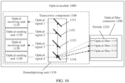
- the optical module 1000 includes an optical receiving unit 1110 (where reference may be made to the optical receiving unit 711 in FIG. 7 ), an optical sending unit 1120 (where reference may be made to the optical sending unit 712 in FIG. 7 ), an optical receiving unit 1130 (where reference may be made to the optical receiving unit 913 in FIG. 9 ), an optical sending unit 1140 (where reference may be made to the optical sending unit 914 in FIG. 9 ), a demultiplexing unit 1150, and an optical fiber connector 1200.
- the optical fiber connector 1200 includes a ferrule 1210, and an optical fiber 1 (where reference may be made to the optical fiber 1 in FIG. 7 ), an optical fiber 2 (where reference may be made to the optical fiber 2 in FIG.
- the demultiplexing unit 1150 corresponds to the demultiplexing unit 612 in FIG. 6
- the optical fiber connector 1200 corresponds to the optical fiber connector 920 in FIG. 6
- the ferrule 1210 corresponds to the ferrule 621 in FIG. 6
- the optical fiber 5 corresponds to the optical fiber 3 in FIG. 6 .
- optical receiving unit 1110 For functions of the optical receiving unit 1110, the optical sending unit 1120, the optical receiving unit 1130, the optical sending unit 1140, the optical fiber 1, and the optical fiber 2, refer to the descriptions in FIG. 7 and FIG. 9 .
- the optical fiber 5 is configured to transmit an optical signal 3 (namely, a third optical signal) received by the optical receiving unit 1130, and the optical fiber 5 is further configured to transmit an optical signal 4 received from the optical sending unit 1140. Wavelengths of any two of an optical signal 1 to the optical signal 4 are different.
- the demultiplexing unit 1150 is configured to: select the optical signal 2 and send the optical signal 2 to the optical fiber 2, is configured to: select the optical signal 1 and send the optical signal 1 to the optical receiving unit 1110, is configured to: select the optical signal 4 and send the optical signal 4 to the optical fiber 5, and is configured to: select the optical signal 3 and send the optical signal 3 to the optical receiving unit 1130.
- the demultiplexing unit 1150 includes a filter 1151 (which is the same as the filter 9151 in FIG. 9 ), a filter 1152 (which is the same as the filter 9152 in FIG. 9 ), a filter 1153 (namely, a third filter), and a filter 1154 (namely, a fourth filter).
- the filter 1153 is configured to: reflect the optical signal 3 and transmit another optical signal.
- the reflector 1154 is configured to: transmit the optical signal 4 and reflect another optical signal.
- the filter 1154 When the filter 1154 receives the optical signal 3 from the optical fiber 5, the filter 1154 reflects the optical signal 3 to the filter 1153, and then the filter 1153 reflects the optical signal 3 to the optical receiving unit 1130.
- the optical sending unit 1140 sends the optical signal 4, the optical signal 4 reaches the optical fiber 5 through the filter 1154.
- the optical receiving unit 1110, the optical sending unit 1120, the optical sending unit 1130, the optical receiving unit 1140, and the demultiplexing unit 1150 are encapsulated in a transceiver component 1100.
- the demultiplexing unit 1150 includes the filter 1151, the filter 1152, the filter 1153, and the filter 1154 is merely used in FIG. 10 .
- Embodiments of this application do not limit the demultiplexing unit 1150 to necessarily include the foregoing elements.
- the demultiplexing unit can select the optical signal 1 and send the optical signal 1 to the optical receiving unit 1110, can select the optical signal 2 and send the optical signal 2 to the optical fiber 2, can select the optical signal 3 and send the optical signal 3 to the optical receiving unit 1130, and can select the optical signal 4 and send the optical signal 4 to the optical fiber 5, the demultiplexing unit falls within the protection scope of embodiments of this application.
- the four optical units included in the optical module 1000 include two optical receiving units and two optical sending units is used in FIG. 10 .
- the four optical units included in the optical module 1000 may include more optical receiving units or include more optical sending units. This is not limited in embodiments of this application. It may be understood that when a function of the optical unit changes, a function of an optical fiber corresponding to the optical unit also changes, and a function of the demultiplexing unit also changes.
- the optical receiving unit 1110 included in the optical module 1000 is replaced with the optical sending unit 1110 configured to send the optical signal 1
- the optical fiber 1 is configured to transmit the optical signal 1 sent by the optical sending unit 1110
- the demultiplexing unit 1150 selects the optical signal 1 and sends the optical signal 1 to the optical fiber 1.
- wavelengths of any two of the optical signal 1 to the optical signal 4 are different is used in FIG. 10 .
- Wavelengths of different optical signals in the optical signal 1 to the optical signal 4 may be the same.
- An embodiment of this application further provides an optical fiber transmission system.
- the optical fiber transmission system includes a baseband unit, a radio frequency unit, and the optical module described in the foregoing embodiment.
- the baseband unit and the radio frequency unit communicate with each other by using the optical module.
- the optical module is deployed on the baseband unit.
Landscapes
- Physics & Mathematics (AREA)
- General Physics & Mathematics (AREA)
- Optics & Photonics (AREA)
- Engineering & Computer Science (AREA)
- Computer Networks & Wireless Communication (AREA)
- Signal Processing (AREA)
- Electromagnetism (AREA)
- Optical Couplings Of Light Guides (AREA)
- Optical Communication System (AREA)
- Mechanical Coupling Of Light Guides (AREA)
Applications Claiming Priority (2)
| Application Number | Priority Date | Filing Date | Title |
|---|---|---|---|
| CN202111497530.8A CN114460694B (zh) | 2021-12-09 | 2021-12-09 | 一种光模块、插芯及光纤连接器 |
| PCT/CN2022/125686 WO2023103590A1 (zh) | 2021-12-09 | 2022-10-17 | 一种光模块、插芯及光纤连接器 |
Publications (2)
| Publication Number | Publication Date |
|---|---|
| EP4431991A1 true EP4431991A1 (de) | 2024-09-18 |
| EP4431991A4 EP4431991A4 (de) | 2025-08-13 |
Family
ID=81405777
Family Applications (1)
| Application Number | Title | Priority Date | Filing Date |
|---|---|---|---|
| EP22903014.3A Pending EP4431991A4 (de) | 2021-12-09 | 2022-10-17 | Optisches modul, ferrule und faseroptischer stecker |
Country Status (6)
| Country | Link |
|---|---|
| US (1) | US20240319460A1 (de) |
| EP (1) | EP4431991A4 (de) |
| JP (1) | JP7866053B2 (de) |
| KR (1) | KR20240110892A (de) |
| CN (1) | CN114460694B (de) |
| WO (1) | WO2023103590A1 (de) |
Families Citing this family (6)
| Publication number | Priority date | Publication date | Assignee | Title |
|---|---|---|---|---|
| CN114460694B (zh) * | 2021-12-09 | 2023-10-20 | 华为技术有限公司 | 一种光模块、插芯及光纤连接器 |
| CN118233009A (zh) * | 2022-12-20 | 2024-06-21 | 宁波环球广电科技有限公司 | 光载无线传输模块结构 |
| CN119667865B (zh) * | 2023-09-21 | 2026-06-02 | 华为技术有限公司 | 光模块、光分合装置、光学连接器、光学组件和通信系统 |
| CN120021175A (zh) * | 2023-11-20 | 2025-05-20 | 上海华为技术有限公司 | 光组件、芯片、有源天线单元、基带单元、基站和通信系统 |
| CN119596483A (zh) * | 2025-01-13 | 2025-03-11 | 四川光恒通信技术有限公司 | 一种双光口收发光器件及其使用方法 |
| CN119596485B (zh) * | 2025-02-10 | 2025-06-17 | 吉林省毅芯科技有限公司 | 一种多路一体化光电转换收发装置 |
Family Cites Families (30)
| Publication number | Priority date | Publication date | Assignee | Title |
|---|---|---|---|---|
| DE19832830A1 (de) * | 1997-10-06 | 1999-04-29 | Hewlett Packard Co | Faseroptischer Periskopverbinder |
| KR100340665B1 (ko) * | 1997-12-31 | 2002-09-25 | 주식회사 머큐리 | 광커넥터용초다심페룰및그페룰에광섬유를삽입하는방법 |
| US7295365B2 (en) * | 2005-10-06 | 2007-11-13 | Bookham Technology Plc. | Optical gain flattening components, optical chips and optical amplifiers and methods employing same |
| JP2008225339A (ja) | 2007-03-15 | 2008-09-25 | Hitachi Cable Ltd | 光学系接続構造、光学部材及び光伝送モジュール |
| CN102349008B (zh) * | 2009-02-14 | 2014-07-02 | 康宁光缆系统有限公司 | 多模光纤组件 |
| JP5158039B2 (ja) * | 2009-08-31 | 2013-03-06 | 日立電線株式会社 | レンズ付き光路変換光ブロックを用いた光トランシーバ並びに光アクティブケーブル |
| CN102576131B (zh) * | 2009-08-31 | 2015-09-02 | 旭化成电子材料株式会社 | 光学旋转连接接头 |
| KR101191323B1 (ko) * | 2010-11-18 | 2012-10-16 | 옵티시스 주식회사 | 광통신 모듈 |
| JP5838748B2 (ja) * | 2011-11-15 | 2016-01-06 | 富士通株式会社 | 光伝送システム、励起光供給制御方法及び励起光供給装置 |
| KR101285766B1 (ko) * | 2012-05-18 | 2013-07-19 | 에스케이텔레콤 주식회사 | 양방향 광 송수신 모듈 |
| US9512985B2 (en) * | 2013-02-22 | 2016-12-06 | Kla-Tencor Corporation | Systems for providing illumination in optical metrology |
| CN104718481B (zh) * | 2013-03-14 | 2016-06-08 | 索尔思光电(成都)有限公司 | 用于光和光电阵列的主动对齐式探测器 |
| JP6268003B2 (ja) * | 2014-03-11 | 2018-01-24 | 株式会社日立製作所 | マルチコアファイバ用接続器、並びにそれを用いた伝送装置 |
| CN205301630U (zh) * | 2016-01-19 | 2016-06-08 | 河北四明升光通信设备有限公司 | 用于单纤双向组件的预埋光纤陶瓷插芯连接器 |
| WO2017134285A1 (en) * | 2016-02-04 | 2017-08-10 | CommScope Connectivity Belgium BVBA | Apparatus for monitoring fiber signal traffic at a fiber connector |
| JP2017156448A (ja) | 2016-02-29 | 2017-09-07 | 住友電気工業株式会社 | 光データリンク |
| CN106059660B (zh) | 2016-06-30 | 2019-01-11 | 瑞斯康达科技发展股份有限公司 | 一种环回检测方法、bbu、rru及光接入网络系统 |
| JP2018041034A (ja) * | 2016-09-09 | 2018-03-15 | 住友電気工業株式会社 | 光コネクタ及び光接続構造 |
| JP6979190B2 (ja) * | 2017-07-21 | 2021-12-08 | 国立研究開発法人情報通信研究機構 | 空間モード多重制御技術 |
| US20190052362A1 (en) * | 2017-08-10 | 2019-02-14 | Luxtera, Inc. | Method And System For A Free Space CWDM MUX/DEMUX For Integration With A Grating Coupler Based Silicon Photonics Platform |
| US10469195B2 (en) * | 2017-10-12 | 2019-11-05 | Luxtera, Inc. | Method and system for eliminating polarization dependence for 45 degree incidence MUX/DEMUX designs |
| US20190129112A1 (en) * | 2017-10-31 | 2019-05-02 | Corning Optical Communications LLC | Laser module system and pluggable laser module for optical telecommunications switching apparatus |
| CN208737044U (zh) * | 2018-05-04 | 2019-04-12 | 华为技术有限公司 | 一种光纤插芯、光纤连接器 |
| CN109212690A (zh) * | 2018-10-29 | 2019-01-15 | 青岛海信宽带多媒体技术有限公司 | 单纤双向光组件及光模块 |
| US11493688B2 (en) * | 2019-06-04 | 2022-11-08 | Electronicsand Telecommunications Research Institute | Optical module |
| CN113448021B (zh) * | 2020-03-24 | 2022-09-23 | 华为技术有限公司 | 一种光纤连接器、单纤双向光组件及光纤传输系统 |
| CN112255740B (zh) * | 2020-11-20 | 2022-03-18 | 长飞光纤光缆股份有限公司 | 一种多芯光纤连接器及其制造方法 |
| CN214750942U (zh) * | 2021-01-18 | 2021-11-16 | 武汉光迅科技股份有限公司 | 一种光纤插芯及光纤连接器 |
| CN214375410U (zh) * | 2021-04-01 | 2021-10-08 | 武汉光迅科技股份有限公司 | 一种多芯光纤用分支器件及光纤连接器 |
| CN114460694B (zh) * | 2021-12-09 | 2023-10-20 | 华为技术有限公司 | 一种光模块、插芯及光纤连接器 |
-
2021
- 2021-12-09 CN CN202111497530.8A patent/CN114460694B/zh active Active
-
2022
- 2022-10-17 WO PCT/CN2022/125686 patent/WO2023103590A1/zh not_active Ceased
- 2022-10-17 JP JP2024534310A patent/JP7866053B2/ja active Active
- 2022-10-17 KR KR1020247022188A patent/KR20240110892A/ko active Pending
- 2022-10-17 EP EP22903014.3A patent/EP4431991A4/de active Pending
-
2024
- 2024-06-06 US US18/735,312 patent/US20240319460A1/en active Pending
Also Published As
| Publication number | Publication date |
|---|---|
| JP2024543632A (ja) | 2024-11-21 |
| JP7866053B2 (ja) | 2026-05-26 |
| US20240319460A1 (en) | 2024-09-26 |
| WO2023103590A1 (zh) | 2023-06-15 |
| KR20240110892A (ko) | 2024-07-16 |
| CN114460694A (zh) | 2022-05-10 |
| EP4431991A4 (de) | 2025-08-13 |
| CN114460694B (zh) | 2023-10-20 |
Similar Documents
| Publication | Publication Date | Title |
|---|---|---|
| US20240319460A1 (en) | Optical module, ferrule, and optical fiber connector | |
| US9917672B2 (en) | Wireless distributed antenna MIMO | |
| US10353148B2 (en) | Mode converter, multimode waveguide transmission apparatus, and method | |
| EP1501206A1 (de) | Zugriffsverfahren und verbindungssystem mittels optischer faser unter verwendung von hybriden dwdm/scm-techniken zwischen basisstationen und fernantennen in einem funkkommunikationssystem | |
| KR20010079835A (ko) | 전자장치가 없는 무선 광학통신 | |
| CN108512623B (zh) | 量子信道与经典信道的合纤qkd系统及其传输方法 | |
| US11990939B2 (en) | Optical module | |
| CN102255669B (zh) | 接收端具有光交叉波分解复用器的cfp光收发器 | |
| CN111147961A (zh) | 垂直腔面发射激光器(vcsel)的双频带波分复用(wdm)链路 | |
| US9621297B2 (en) | Optical communication system, method of bi-directional communication and method of operating a network element | |
| JP5556921B1 (ja) | 加入者側装置登録方法及び光ネットワークシステム | |
| CN102231652A (zh) | 具有光交叉波分复用器的cfp光收发器 | |
| CN109831254B (zh) | 一种利用波分复用技术的光纤直放站系统 | |
| CN112564803A (zh) | 一种5g前传网络传输系统 | |
| EP4300849A1 (de) | Optisches kommunikationssystem und -verfahren, optisches modul und vorrichtung für optisches modul | |
| US20240162988A1 (en) | Distributed wireless system and apparatus | |
| Nishimura et al. | Analog radio-over-fiber-based 5G smart mobile fronthaul networking testbed with an open-source software base-station system | |
| JP7183283B2 (ja) | 光学的に分離されたadcを有するマルチチャネルソフトウェア定義無線受信機 | |
| US20200186274A1 (en) | Optical duplexer and optical transceiving system | |
| CN210536642U (zh) | 光模块组件及光通讯传输系统 | |
| US8714837B2 (en) | Optical fiber connector | |
| CN210297706U (zh) | 有源光纤倍增器及系统 | |
| US11303378B2 (en) | Optical forwarding device | |
| CN215186754U (zh) | 一种基于波分复用技术四波段双向的40Gbps光通讯设备 | |
| CN114488433B (zh) | 一种单光纤高速全双工数据传输装置 |
Legal Events
| Date | Code | Title | Description |
|---|---|---|---|
| STAA | Information on the status of an ep patent application or granted ep patent |
Free format text: STATUS: THE INTERNATIONAL PUBLICATION HAS BEEN MADE |
|
| PUAI | Public reference made under article 153(3) epc to a published international application that has entered the european phase |
Free format text: ORIGINAL CODE: 0009012 |
|
| STAA | Information on the status of an ep patent application or granted ep patent |
Free format text: STATUS: REQUEST FOR EXAMINATION WAS MADE |
|
| 17P | Request for examination filed |
Effective date: 20240610 |
|
| AK | Designated contracting states |
Kind code of ref document: A1 Designated state(s): AL AT BE BG CH CY CZ DE DK EE ES FI FR GB GR HR HU IE IS IT LI LT LU LV MC ME MK MT NL NO PL PT RO RS SE SI SK SM TR |
|
| RIC1 | Information provided on ipc code assigned before grant |
Ipc: G02B 6/42 20060101ALI20250205BHEP Ipc: G02B 6/38 20060101AFI20250205BHEP |
|
| DAV | Request for validation of the european patent (deleted) | ||
| DAX | Request for extension of the european patent (deleted) | ||
| A4 | Supplementary search report drawn up and despatched |
Effective date: 20250716 |
|
| RIC1 | Information provided on ipc code assigned before grant |
Ipc: G02B 6/38 20060101AFI20250710BHEP Ipc: G02B 6/42 20060101ALI20250710BHEP |