EP4431996A1 - Bewegliche vorrichtung, bildverarbeitungsvorrichtung, speichermedium und installationsverfahren für eine bildgebungsvorrichtung - Google Patents
Bewegliche vorrichtung, bildverarbeitungsvorrichtung, speichermedium und installationsverfahren für eine bildgebungsvorrichtung Download PDFInfo
- Publication number
- EP4431996A1 EP4431996A1 EP24163149.8A EP24163149A EP4431996A1 EP 4431996 A1 EP4431996 A1 EP 4431996A1 EP 24163149 A EP24163149 A EP 24163149A EP 4431996 A1 EP4431996 A1 EP 4431996A1
- Authority
- EP
- European Patent Office
- Prior art keywords
- movable apparatus
- angle
- movable
- imaging
- vehicle
- Prior art date
- Legal status (The legal status is an assumption and is not a legal conclusion. Google has not performed a legal analysis and makes no representation as to the accuracy of the status listed.)
- Withdrawn
Links
Images







Classifications
-
- H—ELECTRICITY
- H04—ELECTRIC COMMUNICATION TECHNIQUE
- H04N—PICTORIAL COMMUNICATION, e.g. TELEVISION
- H04N23/00—Cameras or camera modules comprising electronic image sensors; Control thereof
- H04N23/57—Mechanical or electrical details of cameras or camera modules specially adapted for being embedded in other devices
-
- G—PHYSICS
- G02—OPTICS
- G02B—OPTICAL ELEMENTS, SYSTEMS OR APPARATUS
- G02B13/00—Optical objectives specially designed for the purposes specified below
- G02B13/06—Panoramic objectives; So-called "sky lenses" including panoramic objectives having reflecting surfaces
-
- B—PERFORMING OPERATIONS; TRANSPORTING
- B60—VEHICLES IN GENERAL
- B60R—VEHICLES, VEHICLE FITTINGS, OR VEHICLE PARTS, NOT OTHERWISE PROVIDED FOR
- B60R1/00—Optical viewing arrangements; Real-time viewing arrangements for drivers or passengers using optical image capturing systems, e.g. cameras or video systems specially adapted for use in or on vehicles
- B60R1/20—Real-time viewing arrangements for drivers or passengers using optical image capturing systems, e.g. cameras or video systems specially adapted for use in or on vehicles
- B60R1/22—Real-time viewing arrangements for drivers or passengers using optical image capturing systems, e.g. cameras or video systems specially adapted for use in or on vehicles for viewing an area outside the vehicle, e.g. the exterior of the vehicle
- B60R1/23—Real-time viewing arrangements for drivers or passengers using optical image capturing systems, e.g. cameras or video systems specially adapted for use in or on vehicles for viewing an area outside the vehicle, e.g. the exterior of the vehicle with a predetermined field of view
- B60R1/24—Real-time viewing arrangements for drivers or passengers using optical image capturing systems, e.g. cameras or video systems specially adapted for use in or on vehicles for viewing an area outside the vehicle, e.g. the exterior of the vehicle with a predetermined field of view in front of the vehicle
-
- B—PERFORMING OPERATIONS; TRANSPORTING
- B60—VEHICLES IN GENERAL
- B60R—VEHICLES, VEHICLE FITTINGS, OR VEHICLE PARTS, NOT OTHERWISE PROVIDED FOR
- B60R1/00—Optical viewing arrangements; Real-time viewing arrangements for drivers or passengers using optical image capturing systems, e.g. cameras or video systems specially adapted for use in or on vehicles
- B60R1/20—Real-time viewing arrangements for drivers or passengers using optical image capturing systems, e.g. cameras or video systems specially adapted for use in or on vehicles
- B60R1/22—Real-time viewing arrangements for drivers or passengers using optical image capturing systems, e.g. cameras or video systems specially adapted for use in or on vehicles for viewing an area outside the vehicle, e.g. the exterior of the vehicle
- B60R1/23—Real-time viewing arrangements for drivers or passengers using optical image capturing systems, e.g. cameras or video systems specially adapted for use in or on vehicles for viewing an area outside the vehicle, e.g. the exterior of the vehicle with a predetermined field of view
- B60R1/25—Real-time viewing arrangements for drivers or passengers using optical image capturing systems, e.g. cameras or video systems specially adapted for use in or on vehicles for viewing an area outside the vehicle, e.g. the exterior of the vehicle with a predetermined field of view to the sides of the vehicle
-
- B—PERFORMING OPERATIONS; TRANSPORTING
- B60—VEHICLES IN GENERAL
- B60R—VEHICLES, VEHICLE FITTINGS, OR VEHICLE PARTS, NOT OTHERWISE PROVIDED FOR
- B60R1/00—Optical viewing arrangements; Real-time viewing arrangements for drivers or passengers using optical image capturing systems, e.g. cameras or video systems specially adapted for use in or on vehicles
- B60R1/20—Real-time viewing arrangements for drivers or passengers using optical image capturing systems, e.g. cameras or video systems specially adapted for use in or on vehicles
- B60R1/22—Real-time viewing arrangements for drivers or passengers using optical image capturing systems, e.g. cameras or video systems specially adapted for use in or on vehicles for viewing an area outside the vehicle, e.g. the exterior of the vehicle
- B60R1/23—Real-time viewing arrangements for drivers or passengers using optical image capturing systems, e.g. cameras or video systems specially adapted for use in or on vehicles for viewing an area outside the vehicle, e.g. the exterior of the vehicle with a predetermined field of view
- B60R1/26—Real-time viewing arrangements for drivers or passengers using optical image capturing systems, e.g. cameras or video systems specially adapted for use in or on vehicles for viewing an area outside the vehicle, e.g. the exterior of the vehicle with a predetermined field of view to the rear of the vehicle
-
- B—PERFORMING OPERATIONS; TRANSPORTING
- B60—VEHICLES IN GENERAL
- B60R—VEHICLES, VEHICLE FITTINGS, OR VEHICLE PARTS, NOT OTHERWISE PROVIDED FOR
- B60R11/00—Arrangements for holding or mounting articles, not otherwise provided for
- B60R11/04—Mounting of cameras operative during drive; Arrangement of controls thereof relative to the vehicle
-
- G—PHYSICS
- G02—OPTICS
- G02B—OPTICAL ELEMENTS, SYSTEMS OR APPARATUS
- G02B27/00—Optical systems or apparatus not provided for by any of the groups G02B1/00 - G02B26/00, G02B30/00
- G02B27/01—Head-up displays
- G02B27/0101—Head-up displays characterised by optical features
-
- H—ELECTRICITY
- H04—ELECTRIC COMMUNICATION TECHNIQUE
- H04N—PICTORIAL COMMUNICATION, e.g. TELEVISION
- H04N23/00—Cameras or camera modules comprising electronic image sensors; Control thereof
- H04N23/60—Control of cameras or camera modules
- H04N23/698—Control of cameras or camera modules for achieving an enlarged field of view, e.g. panoramic image capture
-
- H—ELECTRICITY
- H04—ELECTRIC COMMUNICATION TECHNIQUE
- H04N—PICTORIAL COMMUNICATION, e.g. TELEVISION
- H04N23/00—Cameras or camera modules comprising electronic image sensors; Control thereof
- H04N23/90—Arrangement of cameras or camera modules, e.g. multiple cameras in TV studios or sports stadiums
-
- H—ELECTRICITY
- H04—ELECTRIC COMMUNICATION TECHNIQUE
- H04N—PICTORIAL COMMUNICATION, e.g. TELEVISION
- H04N5/00—Details of television systems
- H04N5/222—Studio circuitry; Studio devices; Studio equipment
- H04N5/262—Studio circuits, e.g. for mixing, switching-over, change of character of image, other special effects ; Cameras specially adapted for the electronic generation of special effects
- H04N5/265—Mixing
-
- B—PERFORMING OPERATIONS; TRANSPORTING
- B60—VEHICLES IN GENERAL
- B60R—VEHICLES, VEHICLE FITTINGS, OR VEHICLE PARTS, NOT OTHERWISE PROVIDED FOR
- B60R1/00—Optical viewing arrangements; Real-time viewing arrangements for drivers or passengers using optical image capturing systems, e.g. cameras or video systems specially adapted for use in or on vehicles
- B60R1/20—Real-time viewing arrangements for drivers or passengers using optical image capturing systems, e.g. cameras or video systems specially adapted for use in or on vehicles
- B60R1/22—Real-time viewing arrangements for drivers or passengers using optical image capturing systems, e.g. cameras or video systems specially adapted for use in or on vehicles for viewing an area outside the vehicle, e.g. the exterior of the vehicle
-
- B—PERFORMING OPERATIONS; TRANSPORTING
- B60—VEHICLES IN GENERAL
- B60R—VEHICLES, VEHICLE FITTINGS, OR VEHICLE PARTS, NOT OTHERWISE PROVIDED FOR
- B60R2300/00—Details of viewing arrangements using cameras and displays, specially adapted for use in a vehicle
- B60R2300/30—Details of viewing arrangements using cameras and displays, specially adapted for use in a vehicle characterised by the type of image processing
- B60R2300/303—Details of viewing arrangements using cameras and displays, specially adapted for use in a vehicle characterised by the type of image processing using joined images, e.g. multiple camera images
-
- B—PERFORMING OPERATIONS; TRANSPORTING
- B60—VEHICLES IN GENERAL
- B60R—VEHICLES, VEHICLE FITTINGS, OR VEHICLE PARTS, NOT OTHERWISE PROVIDED FOR
- B60R2300/00—Details of viewing arrangements using cameras and displays, specially adapted for use in a vehicle
- B60R2300/60—Details of viewing arrangements using cameras and displays, specially adapted for use in a vehicle characterised by monitoring and displaying vehicle exterior scenes from a transformed perspective
- B60R2300/607—Details of viewing arrangements using cameras and displays, specially adapted for use in a vehicle characterised by monitoring and displaying vehicle exterior scenes from a transformed perspective from a bird's eye viewpoint
-
- B—PERFORMING OPERATIONS; TRANSPORTING
- B60—VEHICLES IN GENERAL
- B60R—VEHICLES, VEHICLE FITTINGS, OR VEHICLE PARTS, NOT OTHERWISE PROVIDED FOR
- B60R2300/00—Details of viewing arrangements using cameras and displays, specially adapted for use in a vehicle
- B60R2300/80—Details of viewing arrangements using cameras and displays, specially adapted for use in a vehicle characterised by the intended use of the viewing arrangement
- B60R2300/8033—Details of viewing arrangements using cameras and displays, specially adapted for use in a vehicle characterised by the intended use of the viewing arrangement for pedestrian protection
-
- B—PERFORMING OPERATIONS; TRANSPORTING
- B60—VEHICLES IN GENERAL
- B60R—VEHICLES, VEHICLE FITTINGS, OR VEHICLE PARTS, NOT OTHERWISE PROVIDED FOR
- B60R2300/00—Details of viewing arrangements using cameras and displays, specially adapted for use in a vehicle
- B60R2300/80—Details of viewing arrangements using cameras and displays, specially adapted for use in a vehicle characterised by the intended use of the viewing arrangement
- B60R2300/8066—Details of viewing arrangements using cameras and displays, specially adapted for use in a vehicle characterised by the intended use of the viewing arrangement for monitoring rearward traffic
-
- G—PHYSICS
- G02—OPTICS
- G02B—OPTICAL ELEMENTS, SYSTEMS OR APPARATUS
- G02B27/00—Optical systems or apparatus not provided for by any of the groups G02B1/00 - G02B26/00, G02B30/00
- G02B27/01—Head-up displays
- G02B27/0101—Head-up displays characterised by optical features
- G02B2027/0123—Head-up displays characterised by optical features comprising devices increasing the field of view
-
- G—PHYSICS
- G02—OPTICS
- G02B—OPTICAL ELEMENTS, SYSTEMS OR APPARATUS
- G02B27/00—Optical systems or apparatus not provided for by any of the groups G02B1/00 - G02B26/00, G02B30/00
- G02B27/01—Head-up displays
- G02B27/0101—Head-up displays characterised by optical features
- G02B2027/0138—Head-up displays characterised by optical features comprising image capture systems, e.g. camera
Definitions
- the present invention relates to a movable apparatus, for example, an automobile and the like, an image processing apparatus, a storage medium, an installation method for an imaging apparatus, and the like.
- CMS camera monitor system
- Japanese Patent Application Laid-Open No. 2008-283527 requires at least four cameras to be mounted on the vehicle so that a bird's-eye video image is captured, and there is the problem that this imposes a load on electric power and system control.
- a first imaging apparatus and a second imaging apparatus provided with an optical system for forming an optical image having a low resolution region in the vicinity of an optical axis and a high resolution region outside the low resolution region on a light receiving surface of an imaging element are used, the first imaging apparatus is installed at a first installation position at a front corner portion of the movable apparatus so that the ground in front of the movable apparatus and the ground in a first side of the movable apparatus are imaged, and the second imaging apparatus is installed at a second installation position at a rear corner portion of the movable apparatus, which is on a diagonal corner side of the first imaging apparatus so that the ground in the rear of the movable apparatus and the ground in a second side of the movable apparatus are imaged.
- an installation method for creating video image in which a vehicle serving as a movable apparatus is looked down on from a virtual viewpoint that is present above the vehicle by using two camera units will be explained. That is, in the first embodiment, an installation method for an imaging apparatus, and a vehicle serving as a movable apparatus having the imaging apparatus installed in this way will be explained.
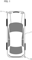
- FIG. 1 is a diagram that explains a positional relation between a camera unit and a vehicle according to the first embodiment.
- the camera unit 11 serving as a first imaging apparatus is installed at the left front corner of the vehicle 1, which is, for example, an automobile
- the camera unit 12 is installed at the right rear corner of the vehicle 1.
- the camera unit 11 is installed so that video images at the lower front and lower left side of the vehicle 1 can be imaged in order to capture a video image for a bird's-eye video image.
- the camera unit 12 is installed so that video images at the lower rear side and the lower right side of the vehicle 1 can be captured in order to capture a video image for a bird's-eye video image.
- the first imaging apparatus is installed at a front corner of the movable apparatus so that the ground in front of the movable apparatus and the ground on the first side of the movable apparatus are imaged.
- the second imaging apparatus is installed at a rear corner of the movable apparatus, on a diagonal corner side of the first imaging apparatus, so that the ground in the rear of the movable apparatus and the ground on the second side of the movable apparatus are imaged.
- the first side is the passenger seat side of the movable apparatus.
- the camera units being installed at the front left corner and the rear right corner of the vehicle 1 is explained, they may be installed at the front right corner and the rear left corner of the vehicle 1. Additionally, the number of camera units may be at least two.
- each of the camera units 11 and 12 in the present embodiment has an optical system and an imaging element for capturing an image that has been formed by an optical system. Additionally, the optical system of each of the camera units 11 and 12 generates an image circle having a characteristic in which the resolution at the peripheral angle of view is higher than the resolution at the center in the optical axis direction and forms an image on the imaging element.
- the optical systems of the camera units 11 and 12 of the present embodiment have optical characteristics of forming an optical image having a low resolution region in the vicinity of the optical axis and a high resolution region outside the low resolution region on the light receiving surface of the imaging element.
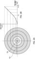
- FIGS. 2A and 2B are diagrams for explaining optical characteristics of the optical system of the camera unit 11 according to the present embodiment. Note that, In the present embodiment, it is assumed that the optical characteristics of the optical systems of the camera units 11 and 12 have substantially the same characteristics, and the optical characteristics of the optical system of the camera unit 11 will be explained as an example with reference to FIG.2 .
- FIG. 2A is a diagram showing an image circle of the optical system of the camera unit 11 and an image height y at each half angle of view (an angle formed by an optical axis and an incident light beam) on the light receiving surface of the imaging element in a contour form.
- FIG. 2B is a diagram illustrating projection characteristics of an image circle representing a relation between the image height y and the half angle of view ⁇ of the optical system of the camera unit 11.
- the horizontal axis represents the half angle of view ⁇
- the vertical axis represents the imaging height (image height) y on the light receiving surface (image surface) of the imaging element of the camera unit 11.
- the optical system of the camera unit in the present embodiment is configured such that the projection characteristic y ( ⁇ ) is different between a region (central region) smaller than a predetermined half angle of view ⁇ a and a region (peripheral region) equal to or larger than the half angle of view ⁇ a.
- the resolution is higher as the inclination of the projection characteristic y ( ⁇ ) in FIG. 2B is larger. That is, the optical system shown in FIG. 2 has projection characteristics in which the image height with respect to the angle of view per unit is higher in the angle of view of the high-resolution region than in the angle of view of the low-resolution region near the optical axis.
- the optical system of the camera unit 11 has optical characteristics in which the resolution in a region where the half angle of view is equal to or larger than ⁇ a is higher than in a region where the half angle of view is smaller than ⁇ a.
- a region (peripheral region) of the peripheral portion of the light receiving surface having a half angle of view ⁇ greater than ⁇ a is referred to as a high resolution region 10a
- a central region (central region) of the light receiving surface having a half angle of view ⁇ of less than ⁇ a is referred to as a low resolution region 10b.
- the optical system of the present embodiment has projection characteristics in which the image height with respect to the angle of view per unit is higher in the angle of view of the high resolution region in comparison to the angle of view of the low resolution region in the vicinity of the optical axis, has the low resolution region in the vicinity of the optical axis, and has the high resolution region outside the low resolution region.
- a circle of a boundary between the high-resolution region 10a and the low-resolution region 10b is referred to as a resolution boundary, and a boundary image on the display screen corresponding to the resolution boundary is referred to as a display resolution boundary or simply referred to as a boundary image.
- the boundary between the high-resolution region 10a and the low-resolution region 10b is not limited to a circular shape, and may be an ellipse in which the projection characteristics y ( ⁇ ) are different for each radial direction, or may be a distorted shape.
- centroid of the light-receiving surface of the image capturing element and the centroid of the high-resolution region 10a or the low-resolution region 10b may be shifted from each other in a predetermined direction. Additionally, the centroid of the high-resolution region 10a or the low-resolution region 10b may be shifted from the position at which the optical axis of the optical system intersects with the light-receiving surface.
- FIG. 3 is a functional block diagram illustrating a configuration example of the image processing system 100 according to the first embodiment, and it is assumed that the image processing system 100 of FIG. 3 is mounted on the vehicle 1. However, a part of the image processing system 100 and the like may be provided at a location that is different from the vehicle 1.
- FIG. 3 Some of the functional blocks shown in FIG. 3 are realized by causing a CPU and the like serving as a computer (not illustrated) included in the image processing system to execute a computer program stored in a memory serving as a storage media (not illustrated).
- each of functional blocks shown in FIG. 3 may not necessarily be incorporated in the same housing, and may be configured by separate devices that are connected to each other via a signal path.
- the camera unit 11 consists of an imaging unit 21 and a camera processing unit 31, and the camera unit 12 consists of an imaging unit 22 and a camera processing unit 32.
- the imaging unit 21 consists of an optical system 21a and an imaging element 21b such as an CMOS image sensor
- the imaging unit 22 consists of an optical system 22a and an imaging element 22b such as an CMOS image sensor.
- Each of the optical systems 21a and 22a of the camera units 11 and 12 is configured by one or more optical lenses and has optical characteristics as shown in FIGS. 2A and 2B .
- the optical systems 21a and 22a respectively form (image) optical images on the light receiving surfaces of the imaging elements 21b and 22b.
- the imaging elements 21b and 22b function as an imaging unit, and photoelectrically convert a formed optical image to output an imaging signal. Note that, on the light receiving surfaces of the imaging elements 21b and 22b, for example, color filters of R, G, and B are arranged for each pixel in a Bayer array, and pixel signals of R, G, and B are sequentially output as imaging signals from the imaging unit 22.
- the camera processing units 31 and 32 have functions of processing imaging signals that have been output from the imaging units 21 and 22.
- the camera processing unit 31 includes an image processing unit 31a, a recognition unit 31b, and a camera information unit 31c
- the camera processing unit 32 includes an image processing unit 32a, a recognition unit 32b, and a camera information unit 32c.
- a CPU serving as a computer and a memory serving as storage media that stores a computer program are incorporated, and the CPU executes the computer program in the memory. Accordingly, a configuration in which processing in the camera processing units 31 and 32 is executed is provided.
- the camera processing units 31 and 32 are not limited to the configuration as described above, and the image processing units 31a and 32a and the recognition units 31b and 32b may be configured by hardware such as a dedicated circuit (ASIC) and a processor (reconfigurable processor, DSP).
- ASIC dedicated circuit
- DSP reconfigurable processor
- the image processing units 31a and 32a perform various kinds of image correction processing, such as white balance adjustment, gain/offset adjustment, gamma processing, color matrix processing, lossless compression processing, and distortion correction processing, on the imaging signals that have been output from the imaging units 21 and 22.
- image correction processing such as white balance adjustment, gain/offset adjustment, gamma processing, color matrix processing, lossless compression processing, and distortion correction processing
- the image processing units 31a and 32a may perform de-Bayer processing on the image data that have been input from the imaging units 21 and 22 according to the Bayer array, and convert the image data into RGB raster format image data. Note that a part of the image processing as described above may be performed by other blocks of the image processing system 100 other than the image processing units 31a and 32a.
- the recognition units 31b and 32b have functions of performing image recognition on predetermined objects (for example, an automobile, a person, an obstacle, and the like) from the image signals subjected to the image processing by the image processing units 31a and 32a, and outputting first image recognition results to an integration processing unit 40.
- predetermined objects for example, an automobile, a person, an obstacle, and the like
- the camera information units 31c and 32c function as holding units that hold camera information such as characteristic information related to characteristics of an optical image and position and orientation information of the camera units, and respectively hold camera information of the camera units 11 and 12 in a memory in advance. Additionally, the camera information units 31c and 32c may hold information from various sensors that are provided in the camera units 11 and 12.
- the held camera information includes, for example, characteristic information of the optical systems 21a and 22a, number of pixels of the imaging elements 21b and 22b, mounting position information and orientation (pitch, roll, yaw, and the like) of the camera units 11 and 12 in the vehicle coordinate system, an optical axis direction, an imaging range, and the like.
- the camera information may include information such as a gamma characteristic, a sensitivity characteristic, a frame rate, an image format of the video image, optical characteristics of the optical system 21a and 22a, and number of pixels of the imaging elements 21b and 22b output from the camera processing unit 31. Additionally, the camera information may include information such as a photoelectric conversion characteristic, coordinates of a mounting position of the camera unit in vehicle coordinates, and orientation information.
- the camera unit mounting position information which serves as a coordinate relative to the vehicle 1, is stored in a memory in the camera information unit in advance.
- the camera information may be information unique to the imaging units 21 and 22 (for example, aberration characteristics of a lens, noise characteristics of an imaging element, and the like).
- the camera information is transmitted to the integration processing unit 40, and is referred to when image processing and the like necessary for display on the display unit is performed in the integration processing unit 40.
- the integration processing unit 40 has functions of displaying the video signals that have been received from the camera units 11 and 12 on the display devices such as a first display unit 50 and a second display unit 51, and notifying a warning display unit 52 and a voice notification unit 53. Furthermore, the integration processing unit 40 further has, for example, an image recognition function of an object crossing the boundary of the imaging range of the camera units 11 and 12.
- the integration processing unit 40 includes an SOC (System On Chip) / FPGA (Field Programmable Gate Array) 41, a CPU 42 serving as a computer, and a memory 43 serving as a storage media. Note that the integration processing unit 40 of the present embodiment is explained as being housed in a housing that is different from the camera unit.
- SOC System On Chip
- FPGA Field Programmable Gate Array
- the functional blocks included in the integration processing unit 40 and the like may be realized by hardware, or may be realized by the CPU 42.
- a dedicated circuit ASIC
- a processor reconfigurable processor, DSP
- the CPU 42 performs various kinds of control of the entire image processing system 100 by executing a computer program stored in the memory 43.
- the SOC/FPGA 41 has an image processing unit 41a, a recognition unit 41b, and an integration control unit 41c.
- the image processing unit 41a has a function of performing image processing such as resolution conversion for display on the display device based on the image signals and the camera information that have been acquired from the camera processing units 31 and 32.
- the image processing unit 41a forms the entire image of each of the imaging units 21 and 22 by combining the image signal of the low-resolution region 10b and the image signal of the high-resolution region 10a of each of the imaging units 21 and 22 for which distortion correction has been performed so as to be smoothly connected to each other. Additionally, the image processing unit 41a performs image processing such as rotation of the image based on, in particular, the arrangement position and the orientation information of the camera in the camera information, and transmits the image signal to the display device.
- the image processing unit 41a connects the images from the imaging units 21 and 22, cuts out each of the connected images, synthesizes a bird's-eye view video in which the car is looked down from a virtual viewpoint above the car, and transmits the synthesized image to the display device as an image signal.
- the image processing unit 41a may realize the function of the image processing unit 41a by a CPU 42 executing the computer program stored in the memory 43. Additionally, the image processing unit may be controlled by a computer.
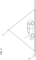
- FIG. 4 is a diagram for explaining a relation between the virtual viewpoint 71 and the vehicle 1 according to the first embodiment, and illustrates an example in which the vehicle 1 is traveling on a road surface 70.
- the coordinate conversion (deformation) of the image acquired by the camera unit 11 and the camera unit 12 is performed by an image processing part 41a as if the road surface 70 is imaged on the assumption that the virtual imaging device is located at the virtual viewpoint 71 directly above the vehicle. That is, a coordinate conversion of the image is performed to generate a virtual viewpoint image from a virtual viewpoint.
- the image processing unit 41a deforms the image that has been acquired from the camera unit 11 and the camera unit 12 based on the calibration data stored in a storage unit 61. Note that the image may be deformed based on various parameters such as a coordinate conversion table based on the calibration data.
- the contents of the calibration data include internal parameters of the camera due to the lens distortion amount of each camera and the deviation from the sensor position, and external parameters representing the relative positional relation between each of the cameras and the vehicle.
- the projection plane of the bird's-eye view may not be a plane that replicates a road surface, and may be, for example, a bowl-shaped three-dimensional shape (curved surface).
- the position of the virtual viewpoint may not necessarily be directly above the vehicle, and may be, for example, a viewpoint position in which the peripheral region is viewed from the diagonally front direction or diagonally rear direction of the vehicle or from the inside of the vehicle.
- the recognition unit 41b performs image recognition processing on a combined image obtained by connecting the images from the imaging units 21 and 22. In addition, it performs image recognition on a predetermined object (for example, an automobile, a person, an obstacle, and the like) in the combined image obtained by connecting the images from the imaging units 21 and 22 to generate a second image recognition result.
- a predetermined object for example, an automobile, a person, an obstacle, and the like
- the integration control unit 41c also has the function of forming a video image signal for displaying a desired image on the first display unit 50 and the second display unit 51 from the entire image of each of the imaging units 21 and 22 for which image processing has been performed. Additionally, a frame for emphatically displaying the recognized object, information on the type, size, position, speed, and the like of the object, CG for warning, and the like are generated.
- CGs for a boundary image for displaying the boundary may be generated based on characteristic information of the optical system, such as display-resolution boundary information that has been acquired from the camera information units 31c and 32c. Then, display processing for superimposing these CGs and characters on the image is performed.
- the first display unit 50 and the second display unit 51 display the image signal and the integrated image recognition result.
- the integration control unit 41c communicates with a travel control unit (ECU) 60 and the like via a communication unit (not illustrated) that is provided therein using protocols such as CAN, FlexRay, or Ethernet.
- display processing is performed to appropriately change information to be displayed based on a vehicle control signal that has been received from the travel control unit (ECU) 60 and the like.
- the range of an image to be displayed on the display unit and the like can be changed according to the moving state of the vehicle that has been acquired by the vehicle control signal.
- the travel control unit (ECU) 60 is a unit that is mounted on the vehicle 1, and has a computer and a memory built therein for performing drive control and direction control of the vehicle 1 in a comprehensive manner.
- Information on the traveling (moving state) of the vehicle such as the traveling speed, the traveling direction, the shift lever, the shift gear, the state of the blinker, the direction of the vehicle according to the geomagnetic sensor, and GPS information and the like serving as vehicle control signals is input from the traveling control unit (ECU) 60 to the integrated processing unit 40.
- the integration control unit 41c may have a function of transmitting information such as a type, a position, a moving direction, and a moving speed of a predetermined target object (for example, an obstacle) recognized by the recognition unit 41b to the travel control unit (ECU) 60.
- the travel control unit (ECU) 60 thereby performs control necessary for the vehicle to avoid obstacles, such as stopping, driving, and changing the travel direction.
- the travel control unit (ECU) 60 functions as a movement control unit that controls the movement of the vehicle based on the integrated image recognition result.
- the first display unit 50 is, for example, a display device that is installed in the vicinity of the center in the vehicle width direction on the upper front portion of the driver's seat of the vehicle 1with a display screen facing the rear of the vehicle, and functions as an electronic rear-view mirror.
- the first display unit 50 may be configured to be used as a mirror when not used as a display, by using a half mirror and the like.
- the first display unit 50 may be configured to include a touch panel and an operation button, acquire an instruction from the user, and output the instruction to the integration control unit 41c. Additionally, instead of a conventional optical side mirror, the first display unit 50 may be used as, for example, an electronic side mirror for confirming right and left obstacles and the like and a display device for displaying a video image for a front cross traffic alert (CTA). The first display unit 50 receives and displays the video signal for the first display unit with a predetermined angle of view that has been generated by the integrated control unit 41c.
- CTA front cross traffic alert
- the second display unit 51 is a display device that is installed, for example, around an operation panel near the center in the vehicle width direction at the front of the driver's seat of the vehicle 1, and functions, for example, as a display device for displaying the downward direction in front of the vehicle.
- the second display unit 51 also functions as a display device for displaying a necessary imaging region generated according to the intended use, similarly to the first display unit 50.
- the integrated control unit 41c receives a signal of a predetermined angle of view necessary for display for the second display unit, and displays the signal.
- information based on various control signals from a navigation system, an audio system, and a travel control unit (ECU) 60 can also be displayed on the second display unit 51. Additionally, a configuration in which a touch panel and an operation button are provided, and an instruction from a user can be acquired may be provided.
- the second display unit 51 may be, for example, a display unit of a tablet computer, and can perform display by being connected to the integration processing unit 40 in a wired manner, or can wirelessly receive and display an image via a communication unit 62.
- a liquid crystal display and an organic EL display and the like can be used as the display elements of the first display unit 50 and the second display unit 51, and the number of display units is not limited to two.
- the integrated control unit 41c determines whether or not a moving object is included in the image based on the recognition results output by the recognition units 31b and 32b and the recognition unit 41b, and outputs the recognition result.
- the moving object here is, for example, a bicycle, a pedestrian, and another vehicle, and is referred to as a detection target in the present embodiment.
- the recognition result output by the integration control unit 41c includes the presence or absence of a detection target, the type and coordinates of the detection target, and speed information.
- the warning display unit 52 issues, for example, a side collision warning to the driver by visual information based on the recognition result that has been output from the integration control unit 41c.
- the warning display unit 52 may be configured by, for example, an LED, and may be configured to perform lighting or blinking in a case in which information indicating that the detection target is present is included in the recognition result.
- warning display unit 52 may be configured by a display, for example, a liquid crystal display.
- a display for example, a liquid crystal display.
- an icon, a text information, and the like are output on the display.
- the warning display unit 52 can be installed, for example, near an end in the vehicle width, in front of the driver's seat of the vehicle 1, such that the display screen is oriented in the driver direction. Additionally, a configuration in which the warning display unit 52 is installed, for example, in the vicinity of the first display unit 50 and the second display unit 51 or also used by the first display unit 50 and the second display unit 51 may be used.
- the voice notification unit 53 outputs a sound based on the recognition result that has been output from the integration control unit 41c. For example, the driver can be notified by outputting a sound using a speaker.
- the voice notification unit 53 is desirably installed, for example, near an end in the vehicle width direction, in front of the driver's seat of the vehicle 1.
- the integration control unit 41c also functions as a warning condition determination unit, and performs control to change the content of the warning output by the warning display unit 52 or the voice notification unit 53 based on the coordinates and speed of the detection target obtained by the recognition units 3 1b to 32b and the recognition unit 41b.
- the integrated control unit 41c may be configured to control the warning display unit 52 so as to increase the degree of warning as the distance to the detection target is shorter.
- the voice notification unit 53 so as to increase the volume or frequency of notification as the distance between the detection target and the side of the vehicle is shorter.
- the integration control unit 41c may be configured to determine whether or not the traveling speed of the own vehicle that has been input from the traveling control unit (ECU) 60 is equal to or less than a predetermined value, and perform the warning display on the warning display unit 52 or the warning notification on the voice notification unit 53 only when the traveling speed is equal to or less than the predetermined value.
- the traveling speed of the own vehicle is high, there is a possibility that the detection target cannot be correctly recognized, and therefore, by adopting the configuration as described above, it is possible to improve the possibility that the side detection can be correctly performed. Additionally, in a case in which the warning display or the warning notification is performed at a speed equal to or lower than the predetermined speed, it is desirable that the traveling speed of the own vehicle is, for example, 30km/h.
- the integration control unit 41c may be configured to determine whether or not the speed of the detection target is within a predetermined range, and to perform warning display on the warning display unit 52 or perform warning notification on the voice notification unit 53 only when it is determined that the speed of the detection target is within the predetermined range.
- the predetermined range of the speed of the detection target is desirably, for example, 5 km/h or more and 20 km/h or less.
- the integration control unit 41c determines whether or not the own vehicle is turning right or left or moving backward based on the movement direction information of the own vehicle that has been output from the travel control unit (ECU) 60. Then, when the vehicle is turning right or left or moving backward, the warning display unit 52 may perform a warning display or the voice notification unit 53 may perform a warning notification.
- the integration processing unit 40 is mounted in the vehicle 1, a part of the processes of the image processing unit 41a, the recognition unit 41b, and the integration control unit 41c of the integration processing unit 40 may be performed, for example, by an external server, external terminals, and the like via a network.
- the imaging units 21 and 22 serving as image acquiring units are mounted in the vehicle 1, it is possible to process a part of the functions of, for example, the camera processing units 31 and 32 and the integrated processing unit 40 (for example, the image processing unit 41a and the like) by an external server or an external terminal.
- an external server, an external terminal, and the like function as an image processing device having the functions of the image processing unit 41a and the like. Additionally, a part or all the functions of the integration processing unit 40 may be provided in the travel control unit (ECU) 60.
- ECU travel control unit
- the storage unit 61 records the entire image of each of the imaging units 21 and 22 generated by the integration processing unit 40. Furthermore, a predetermined frame indicating a recognized object, a character and a CG such as a warning, and an image displayed on a first display unit 50, a second display unit 51 and the like on which the CG is superimposed are recorded together with time and GPS information.
- the integration processing unit 40 reproduces past information recorded in the storage unit 61, and can also display it on the first display unit 50 and the second display unit 51.
- the communication unit 62 can communicate with an external server and the like via a network, transmit information before being recorded in the storage unit 61, past travel history information recorded in the storage unit 61, and the like to the external server and the like, and store the information in the external server and the like.
- the image can be transmitted to an external terminal such as an external tablet terminal, and displayed on the second display unit 51 that is a display unit of the tablet terminal. Additionally, it is also possible to acquire traffic jam information and various information from an external server and the like, and display the information on the first display unit 50 and the second display unit 51 via the integrated processing unit 40.
- An operation unit 63 is used to input various instructions to the image processing system by a user's operation.
- the operation unit includes, for example, a touch panel, an operation button, and the like.
- FIGS. 5A and 5B are diagrams that explain the relation between the characteristics of the optical system of the camera unit 11 installed in the vehicle 1 according to the first embodiment and the imaging region necessary for displaying the bird's-eye view video image.
- FIG. 5A is a side view of the vehicle 1 as viewed from the left side face
- FIG. 5B is a front view of the vehicle 1 as viewed from the front face
- FIGS. 6A and 6B are diagrams that explain the relation between the characteristics of the optical system of the camera unit 12 installed in the vehicle 1 according to the first embodiment and the imaging region necessary for displaying the bird's-eye view video image.
- FIG. 6A is a side face view of the vehicle 1 as viewed from the left side face
- FIG. 6B is a front view of the vehicle as viewed from the rear face.
- the installation position of the camera unit 11 is set as the origin in the X, Y, and Z directions, and the X direction is the vehicle forward direction in the horizontal direction as shown in FIG. 5A .
- the Z direction is a leftward horizontal direction toward the front of the vehicle 1 as shown in FIG. 5B .
- the Y direction is an upward direction along the vertical direction as shown in FIGS. 5A and 5B .
- the horizontal direction and the vertical direction mean the horizontal direction and the vertical direction when the vehicle 1 is in a horizontal state. That is, in a case in which the vehicle 1 is in a horizontal state, the XZ plane is a horizontal plane and the Y direction is a direction along the vertical direction.
- a positive angle is defined in the X direction with respect to the vertical direction, and a negative angle is defined in the -X direction with respect to the vertical direction.
- a negative angle is defined in the -Z direction with respect to the vertical direction.
- E in the XY plane of FIG. 5A represents the viewpoint position of the driver, and is the position of the eyes at the seating position of the driver or the center position of the seat surface for the driver.
- the viewpoint position of the driver is a central position of a seat surface of a virtual driver or a viewpoint position of the virtual driver.
- ⁇ v is the optical axis direction of the camera unit 11, and is an angle from the vertical direction.
- the optical axis of the imaging apparatus is in a downward direction from the installation position (- 90° ⁇ ⁇ v ⁇ + 90°).
- ⁇ v is the angle of view of the high-resolution region 10a of the camera unit 11.
- ⁇ lv is the angle of view of the low-resolution region 10b of the camera unit 11.
- ⁇ h is the optical axis direction of the camera unit 11 and is an angle from the vertical direction.
- ⁇ h is the angle of view of the high-resolution region 10a of the camera unit 11.
- ⁇ lh is the angle of view of the low-resolution region 10b of the camera unit 11.
- x1 in the XY plane of FIG. 5A is the horizontal distance between the camera unit 11 and the viewpoint position E of the driver.
- h1 is the vertical distance between the camera unit 11 and the ground.
- z1 in the YZ plane of FIG. 5B is a distance between the installation position of the camera unit 11 (first installation position) and the side face of the vehicle 1. That is, z1 is the distance between the movable apparatus left side face and the first installation position.
- the installation position of the camera unit 11 is set as the origin in the X, Y, and Z directions, and the X direction is the vehicle forward direction in the horizontal direction as shown in FIG. 6A .
- the Z direction is a rightward horizontal direction toward the rear face of the vehicle 1 as shown in FIG. 6B .
- the Y direction is an upward direction along the vertical direction as shown in FIGS. 6A and 6B .
- x2 in the XY plane in FIG. 6A is the horizontal distance between the camera unit 12 and the viewpoint position E of the driver.
- h2 is the vertical distance between the camera unit 12 and the ground.
- z2 in the YZ plane in FIG. 6B is the distance between the installation position of the camera unit 12 (second installation position) and the side face of the vehicle 1. That is, z2 is the distance between the right side face of the movable apparatus and the second installation position.
- FIG. 7 is a plan view of the vehicle 1 according to the first embodiment as viewed from above, and the X and Z directions correspond to those in FIG. 5 and FIG. 6 .
- the predefined region for the bird's-eye view video image is a region on the ground as shown by hatching in FIGS. 5A and 5B , FIGS. 6A , 6B , and FIG. 7 , and is a region where the driver should confirm the safety of the periphery region of the vehicle.
- the predefined region for the bird's-eye view video image consists of an L-shaped region, region 1, consisting of a front region and a side region of the passenger seat, and an L-shaped region, region 2, consisting of the side region of the driver seat and a rear region.
- the region 1 is a region of the ground surface as shown in FIG. 7 , including a front region defined by a distance d2 forward from the front end of the vehicle, a vehicle width w0, a width w1 and w2 from the side face of the vehicle, and d0 and d1, which are distances in the X direction between the front and rear ends of the vehicle and the driver's viewpoint position E, and a width w1.
- the region2 is an L-shaped region on the ground surface as shown in FIG. 7 , which includes a region on the side of the driver's seat defined by the distances d0 and d1 and the width w2, and a rear region defined by the distance d3 and the vehicle width w0 and the widths w1 and w2.
- the camera unit 11 is installed so as to satisfy the following formulae 2 to 5 so that the range of the region 1 within the imaging range of the camera unit 11 is included.
- the camera unit 12 is installed so as to satisfy Formulae 6 to 9 below so that the range of the region2 within the imaging range of the camera unit 12 is included.
- the combined the camera unit 11 and the camera unit 12 can capture images of the periphery of the vehicle 1 without any gap. Note that it is assumed that the installation conditions of Formula 2 to Formula 9 described above are first conditions.
- the camera unit 11 is disposed at a position where the vehicle 1 is not reflected in the center of the optical axis in order to capture an image of the front face of the vehicle and side faces of the vehicle. That is, the offset x1 of the camera unit for imaging the front of the vehicle is set to be larger than the distance d0 from the viewpoint position E to the front end of the vehicle 1. Furthermore, the offset z1 of the camera unit 11 is installed outside the side of the car 1 (- Z direction in FIG. 5 ) so that the images of the side faces of the vehicle are imaged.
- the camera unit 12 is disposed at a position where the vehicle 1 is not reflected in the center of the optical axis in order to capture an image of the rear and side faces of the vehicle. That is, the offset x2 of the camera unit 12 is set to be larger than distance d1 from the viewpoint position E to the rear face end of the vehicle 1 in order to capture an image of the rear of the vehicle. Furthermore, the offset z2 of the camera unit 12 is set outside (in the Z direction in FIG. 6 ) the side of the vehicle 1 so that an image in the rear of the side face of the vehicle is captured.
- the camera unit 11 and the camera unit 12 are installed so that a high resolution image in the horizontal direction can be captured for safety confirmation of the periphery region of the vehicle.
- the installation conditions for this will be explained.
- the camera unit 11 and the camera unit 12 are installed so that the front, rear, left, and right horizontal directions can be appropriately confirmed.
- the camera unit 11 is installed so as to satisfy Formula 10 and Formula 11 below. That is, the installation is performed so as to include both the high-resolution region 10a in the left direction and in the rear side (( ⁇ h - ⁇ h - ⁇ lh) to (cph - ⁇ lh) in the right direction toward the front of the vehicle and ( ⁇ v + ⁇ lv) to ( ⁇ v + ⁇ v + ⁇ lv) in the rear of the vehicle).
- the camera unit 12 is also installed so as to satisfy Formula 12 and Formula 13 below. That is, the unit is installed so as to include both the high-resolution region 10a in the left direction and on the rear side (( ⁇ h + ⁇ lh) to ( ⁇ h + ⁇ h + ⁇ lh) in the right direction toward the front of the vehicle and ( ⁇ v- ⁇ v- ⁇ lv) to ( ⁇ v- ⁇ lv) in the rear of the vehicle).
- the camera unit 11 and the camera unit 12 will be explained by giving actual specific values.
- d2 2m
- d3 2m
- w1 2m
- w2 2m
- the angle ⁇ v in the vertical direction and the angle cph in the horizontal direction of the optical axis of the camera unit 11 are respectively set so as to satisfy the conditions of -36.4° ⁇ ⁇ v ⁇ 15.9°, -18.9° ⁇ ⁇ h ⁇ 39.5° obtained from the above Formulae 2 to 5.
- the angle ⁇ v in the vertical direction and the angle cph in the horizontal direction of the optical axis of the camera unit 12 are respectively set so as to satisfy the conditions of -18.1° ⁇ ⁇ v ⁇ 40.1°, -43.3° ⁇ ⁇ h ⁇ 21.3° obtained from the above Formulae 6 to 9.
- the angle ⁇ v of the optical axis of the camera unit 11 in the vertical direction and the angle cph of the optical axis of the camera unit 11 in the horizontal direction are respectively calculated from Formula 10 and Formula 11.
- the camera unit 11 is installed so as to satisfy 0.0° ⁇ v ⁇ 23.6°, -23.6° ⁇ h ⁇ 0.0°, which are the calculation results.
- angle ⁇ v in the vertical direction and the angle cph in the horizontal direction of the optical axis of the camera unit 12 may respectively be set so as to satisfy 0.0° ⁇ ⁇ v ⁇ 23.6°, -23.6° ⁇ cph ⁇ 0.0°, which are obtained from the above Formula 12 and Formula 13.
- the camera unit 11 is installed so as to satisfy 0.0° ⁇ v ⁇ 15.9°, -18.9° ⁇ h ⁇ 0.0° that are obtained from Formula 2 to Formula 5, Formula 10, and Formula 11 so that the predefined region of the bird's-eye view video image is included in the angle of view and the image in a distance away from the periphery region of the vehicle is captured.
- the camera unit 12 is installed so as to satisfy - 18.1° ⁇ v ⁇ 0.0°, 0.0° ⁇ h ⁇ 21.3°, which are obtained from Formula 6 to Formula 9, Formula 12, and Formula 13.
- the first embodiment by installing two camera units under the first condition and the second condition, it is possible to capture the image of the predefined region for the bird's-eye view video image and further capture the periphery of the vehicle with high resolution.
- an installation condition in a case in which the camera unit is installed so as to also serve as the electronic side mirror will be explained.
- an imaging region that is necessary for the electronic side mirror display (a predefined region on the rear of the side face of the vehicle) will be explained with reference to FIG. 8 .
- FIG. 8 is a plan view of the vehicle 1 according to the second embodiment as viewed from above, and the X and Z directions are based on the installation position of the camera unit 11 as an origin.
- the predefined region on the rear of the side face of the vehicle is a region on the ground surface as shown by hatching in FIG. 8 , and is a region that the driver should check with the side mirror of the vehicle.
- the predefined region on the rear of the side face of the vehicle is a region on the ground surface defined by a width w3 from a side face of the vehicle at a rear distance d4 from the driver's viewpoint E and a width w4 from a side face of the vehicle at a rear distance d5 from the driver's viewpoint E.
- the region on the passenger seat side is referred to as "region3”
- the region on the driver's seat side is referred to as "region4".
- the regions and the region4 have a line symmetric shape with respect to the center line in the longitudinal direction of the vehicle 1.
- the camera unit 11 installed on the passenger seat side can horizontally capture a high-resolution image while capturing an image of the predefined region, region3, in the rear of the side face of the vehicle. Since the far side of the region 3 that is the predefined region in the rear of the side face of the vehicle continues to an unlimited distance in the rear of the vehicle, the camera unit 11 is installed so that an unlimited distance, that is, a horizontal direction of the width w4 can be imaged.
- the installation in which an image can be captured in the ground direction to the horizontal direction in the vicinity with high resolution is desirable.
- the camera unit 11 is installed so as to satisfy Formula 14 below in order that the horizontal angle (- 90 °) is included in the range between the high-resolution region 10a ( ⁇ v- ⁇ v- ⁇ lv) and (the angle of ( ⁇ v - ⁇ lv) of the camera unit 11.
- the unit is installed so that the leading region (region of the width w3) of the predefined region, region 3, in the traveling direction, which is separated backward by d4 from the viewpoint position E, is included in the imaging angle of view in addition to Formula 14 so that the predefined region, region 3, on the side face of the vehicle is included in the imaging angle of view of the camera unit 11.
- the camera unit 11 can capture an image in the horizontal direction with high resolution while capturing the predefined region, region 3, in the rear of the side face of one side of the vehicle 1. Note that, here, the side face on one side of the vehicle 1 is the side face on the passenger seat side.
- the imaging region that is necessary for the display for the front monitoring device for confirming the safety in front (the predefined region under the front face of the vehicle) will be explained with reference to FIG. 9 to FIG. 11 .
- FIG. 9 is a side view for explaining a relation between the camera unit 11 and the vehicle 1 according to the third embodiment
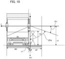
- FIG. 10 is a view for explaining a predefined region below the front face of the vehicle according to the third embodiment, and is a front view when the vehicle 1 is viewed from the front face.
- FIG. 11 is a plan view of the vehicle 1 as viewed from above, for explaining the predefined region on the lower front side of the vehicle and on the side of the passenger seat side of the vehicle according to the third embodiment.
- the X, Y, and Z directions and angles in FIG. 9 to FIG. 11 respectively correspond to those in FIGS. 5A, 5B , and FIG. 8 , and have the same relation.
- E in FIG. 9 and FIG. 11 represents the viewpoint position of the driver, and the positional relation between the camera unit 11 and the vehicle 1 (x1, h1, z1) and the relation between the optical axis and the imaging angle of view ( ⁇ v, ⁇ v, ⁇ lv, ⁇ h, ⁇ h, ⁇ lh) in FIG. 9 and FIG. 10 are also the same as those in FIGS. 5A and 5B .
- the predefined region below the front face of the vehicle and the predefined region on the side face on the passenger seat side will be explained with reference to FIG. 9 to FIG. 11 .
- the predefined region below the front face of the vehicle is a region to be confirmed by the driver with the side under mirror of the vehicle.
- d10 is a distance from the leading end of the vehicle 1 to a distance under the front side to be confirmed
- d0 is a distance from the viewpoint position E to the leading end of the vehicle 1
- w0 is a width of the vehicle 1
- w8 is a distance to a distant location on the side of the vehicle body to be confirmed.
- the predefined region under the front face of the vehicle is a region represented by a region on the ground surrounded by the distance d10 and (w0+w8). Therefore, the installation condition in which the camera unit 11 can image the predefined region in the front lower direction of the vehicle 1 is a condition in which the imaging angle of view of the camera unit 11 includes the region surrounded by d10 and (w0 + w8) (fourth condition).
- the camera unit 11 is installed so as to satisfy Formula 16 and Formula 17 below as a fourth condition so that the ground surface at the distance d10 from the front end portion is included in the imaging angle of view ( ⁇ v - ⁇ v - ⁇ lv) to ( ⁇ v + ⁇ v + ⁇ lv) of the camera unit 11.
- the camera unit is installed so as to satisfy the following Formula 18 and Formula 19 so that the end portions of w0 and w8 are included in the range of (w0+w8) in the imaging angle of view of the camera unit 11.
- Formula 18 and Formula 19 the end portions of w0 and w8 are included in the range of (w0+w8) in the imaging angle of view of the camera unit 11.
- the predefined region under the front of the vehicle is a region that the driver should check with a side under mirror of the vehicle.
- a forward distance on the side face on the passenger seat side to be confirmed from the viewpoint position E is d8
- a rearward distance on the side face on the passenger seat side to be confirmed is d9
- a distance to a distant location on the side of the vehicle body to be confirmed is w7.
- the installation conditions under which the camera unit 11 can capture an image of the predefined region on the side face of the passenger seat side of the vehicle 1 satisfy Formula 20 and Formula 21 below as a fifth condition so that the region surrounded by (d8+d9) and w7 is included in the imaging angle of view of the camera unit 11.
- Formula 20 and Formula 21 below as a fifth condition so that the region surrounded by (d8+d9) and w7 is included in the imaging angle of view of the camera unit 11.
- the camera unit 11 is installed so as to satisfy the following Formula 22 as an installation condition so that the end portion of w7 is included in the imaging angle of view of the camera unit 11.
- Formula 22 an installation condition so that the end portion of w7 is included in the imaging angle of view of the camera unit 11.
- the camera unit 11 it is possible to realize a movable apparatus capable of imaging a predefined region below the forward side of the vehicle in a wide range with high resolution by installing the imaging apparatus so as to satisfy such conditions.
- the present embodiment may not satisfy all of the above first condition to the fifth condition, and the installation may be performed so as to satisfy at least one of the first condition and the second condition and at least one of the third condition to the fifth condition.
- a field of view in a wider range (a predefined region of a wide range in the rear of the side face of the vehicle) than the above-described predefined region in the rear of the side face of the vehicle can be confirmed.
- the predefined region in a wide range in the rear of the side face of the vehicle will be explained with reference to FIG. 12 .
- FIG. 12 is a plan view of the vehicle 1 as viewed from above, for explaining a predefined region in the wide angle in the rear of the side face of the vehicle according to the fourth embodiment.
- the region on the ground surface on the side and rear of the vehicle as shown by the hatching in FIG. 12 is the same as the predefined region in the rear of the side face of the vehicle as explained in FIG. 9 .
- the predefined regions in a wide range in the rear of the side face of the vehicle are ground surface regions (region 5, region 6) defined by a width w5 from the vehicle side face at a distance d6 rearward from the driver's viewpoint position E and a width w6 from the vehicle body side face at a distance d7 rearward from the viewpoint position E.
- the camera unit 11 disposed on the passenger seat side can correspond to the installation conditions of a large vehicle by being installed so that the predefined region, region 5, of a wide range in the rear of the side face of the vehicle is included in the imaging range.
- This detection region is a region in which there is a high possibility of a vehicle accident involving a turn or collision when an object is present in the detection region when the own vehicle, for example, turns left.
- the camera unit 11 disposed on the passenger seat side can detect a moving object on the passenger seat side by being installed such that the detection region is included in the imaging range.
- the relation between the predefined region, the detection region, and the object on the side of the vehicle passenger seat side in the fifth embodiment will be explained with reference to FIG. 13 and FIG. 14 .
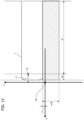
- FIG. 13 is a schematic plan view of the vehicle 1 as viewed from above for explaining the predefined region on the side face on the passenger seat side of the vehicle according to the fifth embodiment.
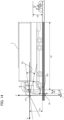
- FIG. 14 is a side face view of the vehicle 1 according to the fifth embodiment as viewed from the side.
- the X, Y, and Z directions and angles in FIG. 13 and FIG. 14 have the same relation as in FIG. 9 to FIG. 11 .
- E described in FIG. 13 and FIG. 14 is the same as E described in FIG. 9 to FIG. 11 , and represents the viewpoint position of the driver.
- the predefined region on the side face of the passenger seat side of the vehicle is a region surrounded by a distance (d0+d1) from the front face of the vehicle body to the rear side of the vehicle body to be detected and a distance w10 from the side face of the vehicle body to a distance on the side of the vehicle body to be detected.
- the size of the moving object to be detected is an object having a height d3.
- the detection region for side collision warning is a region surrounded by the predefined region on the side face of the vehicle passenger seat side and the height h3.
- the camera unit 11 is installed so that the detection region for the side collision warning is included in the angle of view, and thus can correspond to the installation conditions of a large vehicle. It is desirable that the height h1 of the camera unit 11 is higher than h3 of the moving object to be detected. That is, it is desirable to satisfy the following Formula 23. h1 ⁇ h3
- the moving object having the height h3 can be included in the imaging range without making the imaging angle of view of the camera unit wider than the condition of h1 ⁇ h3.
- h3 2 meters.
- the offset x 1 of the camera unit is larger than the front end of the vehicle, the ground of the entire region of the w10 at that position is included in the imaging range so that the detection target in the detection region is reflected.
- the camera unit 11 is disposed on the outside obliquely front of the corner of the vehicle body on the passenger seat side in order to perform high-resolution imaging for a plurality of required imaging ranges and high-resolution imaging directions with fewer cameras.
- the installation conditions of the camera unit 11 on the passenger seat side according to the fifth embodiment have been explained.
- the camera unit 11 is disposed on the driver's seat side
- the camera unit 12 is disposed at a position where the vehicle 1 is not reflected in the center of the optical axis.
- the offset x2 of the camera unit 12 is larger than the leading end of the rear face of the vehicle 1.
- the offset z2 of the camera unit 12 is installed more toward the outside (Z direction in FIG. 6 ) than the side of the vehicle 1.
- FIG. 15 is a plan view of the vehicle 1 viewed from above for explaining the predefined region below the rear face of the vehicle according to the sixth embodiment.
- the X, Y, and Z directions and angles in FIG. 15 respectively correspond to those in FIGS. 6A and 6B , and have the same relation.
- E in FIG. 15 is the same as E in FIG. 6A , and represents the viewpoint position of the driver.
- the positional relation (x2, h2, z2) between the camera unit 12 and the vehicle 1 and the relation ( ⁇ v, ⁇ v, ⁇ lv, ⁇ h, ⁇ h, ⁇ hl) between the optical axis and the imaging angle of view as shown in FIG. 15 are also the same as those in FIGS. 6A and 6B .
- d1 in FIG. 15 is a distance from the driver's viewpoint position E to the rear face end of the vehicle 1.
- the predefined region below the rear face of the vehicle shown in FIG. 15 is a region to be confirmed by the driver on the display device when the vehicle moves backward, and a distance from a predetermined position on the side to be confirmed, which is only d11 away from the rear face of the vehicle, to a predetermined position on the far side to be confirmed from the rear face of the vehicle is d12, and the vehicle width of the vehicle 1 is w0.
- the predefined region below the rear face of the vehicle is a region represented by a region on the ground face surrounded by d12 and w0, and it is desirable that the camera unit 12 can capture an image of an object at a height h3 within a predetermined predefined region to be confirmed in the rear of the vehicle 1.
- the installation condition (sixth condition) under which the camera unit 12 can capture an image of the predefined region under the rear face of the vehicle is a condition in which the imaging angle of view of the camera unit 12 includes a region surrounded by d12, w0, and height h3.
- the camera unit 12 is installed to satisfy the following installation conditions (Formula 24, Formula 25, and Formula 27) or installation conditions (Formula 24, Formula 26, and Formula 28) such that the above-described region is included within the imaging angle of view ( ⁇ v - ⁇ v - ⁇ lv) to ( ⁇ v + ⁇ v + ⁇ lv) of the camera unit 12.
- z2 is a distance between the installation position of the camera unit 12 (second installation position) and the side face of the vehicle.
- the camera unit 12 can appropriately capture an image of the predefined region in the downward direction in the rear of the vehicle.
- This detection region is a region in which there is a high possibility of a vehicle accident involving a turn or collision when an object is present in the detection region when the own vehicle, for example, turns left.
- the camera unit is disposed on the passenger seat side, it is possible to correspond to the installation conditions for detecting a moving object on the passenger seat side by performing the installation in which the detection region is included in the imaging range.
- FIG. 16 is a diagram for explaining a predefined region in the rear of the vehicle according to the seventh embodiment, and as shown in FIG. 16 , the predefined region in the rear of the vehicle is set to a range of width w12 and distance d13 as a predefined region. Additionally, a width from the side face of the vehicle to the predefined region is set to a width w11. An installation condition (condition 7) under which the camera unit 12 can capture an image of such a predefined region will be explained.
- the camera unit 12 can realize a movable apparatus capable of capturing an image of a predefined region in the rear of the vehicle with high resolution.
- the camera unit 12 is disposed on the outside diagonally in the rear from the rear corner (corner portion) of the passenger seat side.
- the installation may be performed so as to satisfy at least one of the first condition and the second condition and at least one of the sixth condition and the seventh condition.
- the installation conditions of the camera unit 12 on the driver's seat side have been explained. Note that a plurality of required imaging ranges and high-resolution imaging directions on the driver seat side can be imaged with a number of cameras less than the number of directions in which high-resolution imaging is necessary by disposing the camera unit in similar installation conditions also in the case in which the camera unit is disposed on the passenger's seat side. Additionally, it is also desirable that, in the case in which the camera unit is disposed on the passenger seat side, it is disposed on the outside diagonally in the rear from the rear corner of the passenger seat side.
- the movable apparatus is not limited to an automobile and may be any movable apparatus.
- the movable apparatus includes a ship, an airplane, a drone, a robot, an AAV, and the like.
- the movable apparatus may be remotely controlled from an external device based on the bird's-eye image that has been generated by the external device.
- a computer program realizing the function of the embodiments described above may be supplied to the movable apparatus and the like through a network or various storage media. Then, a computer (or a CPU, an MPU, or the like) of the movable apparatus and the like may be configured to read and execute the program. In such a case, the program and the storage medium storing the program configure the present invention. Then, a computer (or a CPU, an MPU, or the like) of the movable apparatus and the like may be configured to read and execute the program. In such a case, the program and the storage medium storing the program configure the present invention.
- the present invention also includes those realized using, for example, using, for example, at least one processor or circuit configured to function of the embodiments explained above. Note that a plurality of processors may be used for distributed processing.
- a first imaging apparatus and a second imaging apparatus provided with an optical system for forming an optical image having a low resolution region in the vicinity of an optical axis and a high resolution region outside the low resolution region on a light receiving surface of an imaging element are used, the first imaging apparatus is installed at a first installation position in a front corner portion of the movable apparatus so that the ground in front of the movable apparatus and the ground in a first side of the movable apparatus are imaged, and the second imaging apparatus is installed at a second installation position at a rear corner portion of the movable apparatus, which is on a diagonal corner side of the first imaging apparatus so that the ground in the rear of the movable apparatus and the ground in a second side of the movable apparatus are imaged.
Landscapes
- Engineering & Computer Science (AREA)
- Multimedia (AREA)
- Signal Processing (AREA)
- Mechanical Engineering (AREA)
- Physics & Mathematics (AREA)
- General Physics & Mathematics (AREA)
- Optics & Photonics (AREA)
- Closed-Circuit Television Systems (AREA)
- Cameras In General (AREA)
- Studio Devices (AREA)
Applications Claiming Priority (1)
| Application Number | Priority Date | Filing Date | Title |
|---|---|---|---|
| JP2023042522A JP2024131942A (ja) | 2023-03-17 | 2023-03-17 | 移動体、画像処理装置、コンピュータプログラム、及び撮像装置の設置方法 |
Publications (1)
| Publication Number | Publication Date |
|---|---|
| EP4431996A1 true EP4431996A1 (de) | 2024-09-18 |
Family
ID=90365289
Family Applications (1)
| Application Number | Title | Priority Date | Filing Date |
|---|---|---|---|
| EP24163149.8A Withdrawn EP4431996A1 (de) | 2023-03-17 | 2024-03-13 | Bewegliche vorrichtung, bildverarbeitungsvorrichtung, speichermedium und installationsverfahren für eine bildgebungsvorrichtung |
Country Status (4)
| Country | Link |
|---|---|
| US (1) | US12445742B2 (de) |
| EP (1) | EP4431996A1 (de) |
| JP (1) | JP2024131942A (de) |
| CN (1) | CN118665346A (de) |
Citations (7)
| Publication number | Priority date | Publication date | Assignee | Title |
|---|---|---|---|---|
| US6476855B1 (en) * | 1998-05-25 | 2002-11-05 | Nissan Motor Co., Ltd. | Surrounding monitor apparatus for a vehicle |
| US20050083427A1 (en) * | 2003-09-08 | 2005-04-21 | Autonetworks Technologies, Ltd. | Camera unit and apparatus for monitoring vehicle periphery |
| JP2008283527A (ja) | 2007-05-11 | 2008-11-20 | Alpine Electronics Inc | 画像処理装置 |
| US20140002660A1 (en) * | 2011-09-30 | 2014-01-02 | Panasonic Corporation | Birds-eye-view image generation device, and birds-eye-view image generation method |
| EP3451651A1 (de) * | 2016-04-27 | 2019-03-06 | Sony Corporation | Bildgebungssteuerungsvorrichtung, bildgebungssteuerungsverfahren und bildgebungsvorrichtung |
| WO2023276819A1 (ja) * | 2021-06-29 | 2023-01-05 | キヤノン株式会社 | 撮像システム |
| JP2023042522A (ja) | 2022-03-31 | 2023-03-27 | 株式会社ニューギン | 遊技機 |
Family Cites Families (2)
| Publication number | Priority date | Publication date | Assignee | Title |
|---|---|---|---|---|
| JP5715778B2 (ja) * | 2010-07-16 | 2015-05-13 | 東芝アルパイン・オートモティブテクノロジー株式会社 | 車両用画像表示装置 |
| JP7500527B2 (ja) * | 2021-09-24 | 2024-06-17 | キヤノン株式会社 | 画像処理システム、移動装置、画像処理方法、およびコンピュータプログラム |
-
2023
- 2023-03-17 JP JP2023042522A patent/JP2024131942A/ja active Pending
-
2024
- 2024-03-08 US US18/599,295 patent/US12445742B2/en active Active
- 2024-03-13 EP EP24163149.8A patent/EP4431996A1/de not_active Withdrawn
- 2024-03-15 CN CN202410300518.0A patent/CN118665346A/zh active Pending
Patent Citations (7)
| Publication number | Priority date | Publication date | Assignee | Title |
|---|---|---|---|---|
| US6476855B1 (en) * | 1998-05-25 | 2002-11-05 | Nissan Motor Co., Ltd. | Surrounding monitor apparatus for a vehicle |
| US20050083427A1 (en) * | 2003-09-08 | 2005-04-21 | Autonetworks Technologies, Ltd. | Camera unit and apparatus for monitoring vehicle periphery |
| JP2008283527A (ja) | 2007-05-11 | 2008-11-20 | Alpine Electronics Inc | 画像処理装置 |
| US20140002660A1 (en) * | 2011-09-30 | 2014-01-02 | Panasonic Corporation | Birds-eye-view image generation device, and birds-eye-view image generation method |
| EP3451651A1 (de) * | 2016-04-27 | 2019-03-06 | Sony Corporation | Bildgebungssteuerungsvorrichtung, bildgebungssteuerungsverfahren und bildgebungsvorrichtung |
| WO2023276819A1 (ja) * | 2021-06-29 | 2023-01-05 | キヤノン株式会社 | 撮像システム |
| JP2023042522A (ja) | 2022-03-31 | 2023-03-27 | 株式会社ニューギン | 遊技機 |
Non-Patent Citations (1)
| Title |
|---|
| "Handbook of Optical Systems", 1 January 2008, WILEY-VCH, Weinheim, DE, ISBN: 978-3-527-40380-6, article HERBERT GROSS ET AL: "Handbook of Optical Systems, Vol.4: Survey of Optical Instruments", pages: 338 - 346, XP055237921 * |
Also Published As
| Publication number | Publication date |
|---|---|
| US20240314455A1 (en) | 2024-09-19 |
| JP2024131942A (ja) | 2024-09-30 |
| CN118665346A (zh) | 2024-09-20 |
| US12445742B2 (en) | 2025-10-14 |
Similar Documents
| Publication | Publication Date | Title |
|---|---|---|
| EP4344953A1 (de) | Bewegliche vorrichtung und installationsverfahren für eine bildgebungsvorrichtung | |
| US12214733B2 (en) | Camera unit installing method, moving device, image processing system, image processing method, and storage medium | |
| EP4155129A1 (de) | Mobiles objekt, bildverarbeitungsverfahren und speichermedium | |
| US12165419B2 (en) | Movable apparatus, control method for movable apparatus, and storage medium | |
| US12028603B2 (en) | Image processing system, image processing method, storage medium, image pickup apparatus, and optical unit | |
| US12417642B2 (en) | System to integrate high distortion wide-angle camera recognition with low distortion normal-angle camera recognition | |
| US12530904B2 (en) | Image processing system, image processing method, and storage medium | |
| US20230098424A1 (en) | Image processing system, mobile object, image processing method, and storage medium | |
| US20230100099A1 (en) | Image processing system, image processing method, and storage medium | |
| EP4344952A1 (de) | Bewegliche vorrichtung und installationsverfahren für eine bildgebungsvorrichtung | |
| US20250071232A1 (en) | Imaging apparatus and imaging system | |
| EP4431996A1 (de) | Bewegliche vorrichtung, bildverarbeitungsvorrichtung, speichermedium und installationsverfahren für eine bildgebungsvorrichtung | |
| JP2006254318A (ja) | 車載用カメラ及び車載用監視装置並びに前方道路領域撮像方法 | |
| EP4563414A1 (de) | Bewegliche vorrichtung |
Legal Events
| Date | Code | Title | Description |
|---|---|---|---|
| PUAI | Public reference made under article 153(3) epc to a published international application that has entered the european phase |
Free format text: ORIGINAL CODE: 0009012 |
|
| STAA | Information on the status of an ep patent application or granted ep patent |
Free format text: STATUS: THE APPLICATION HAS BEEN PUBLISHED |
|
| AK | Designated contracting states |
Kind code of ref document: A1 Designated state(s): AL AT BE BG CH CY CZ DE DK EE ES FI FR GB GR HR HU IE IS IT LI LT LU LV MC ME MK MT NL NO PL PT RO RS SE SI SK SM TR |
|
| STAA | Information on the status of an ep patent application or granted ep patent |
Free format text: STATUS: REQUEST FOR EXAMINATION WAS MADE |
|
| 17P | Request for examination filed |
Effective date: 20250318 |
|
| STAA | Information on the status of an ep patent application or granted ep patent |
Free format text: STATUS: THE APPLICATION HAS BEEN WITHDRAWN |
|
| 18W | Application withdrawn |
Effective date: 20260226 |